Previous Screen
Product: MINI HYD EXCAVATOR
Model: 302CR MINI HYD EXCAVATOR RHM
Configuration: 302 CR Mini Hydraulic Excavator RHM00001-UP (MACHINE) POWERED BY C1.1 Engine
Disassembly and Assembly
Blade Cylinder - Disassemble
SMCS - 7562-015-BG
Disassembly Procedure Table 1
Start By:
Shutdown SIS
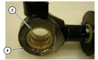
1. Remove seals (1) from barrel end of blade cylinder (2). Remove seals (3) from rod end of blade cylinder (4).
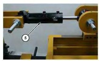
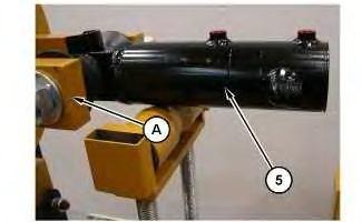
2. Mount blade cylinder (5) into Tooling (A).
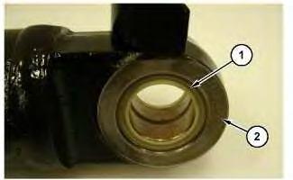 Illustration 1
g06295269
Illustration 2
g06295274
Illustration 3
g06295283
Illustration 1
g06295269
Illustration 2
g06295274
Illustration 3
g06295283
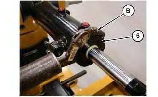

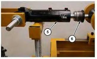 Illustration 4
g06295331
3. Use Tooling (B) to loosen cylinder nut (6).
Illustration 5
g06295371
Illustration 6
g06295383
4. Remove cylinder nut (6) from the barrel. Place support under barrel end of cylinder (5).
Illustration 4
g06295331
3. Use Tooling (B) to loosen cylinder nut (6).
Illustration 5
g06295371
Illustration 6
g06295383
4. Remove cylinder nut (6) from the barrel. Place support under barrel end of cylinder (5).
Illustration 7
5. Back the cylinder bench out to remove rod end (9) from the cylinder barrel. Remove set screw and ball (7) from piston (8).
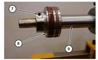
Illustration 8
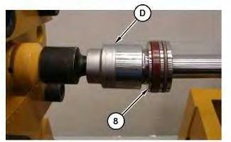
6. Use Tooling (D) to remove piston (8).
Illustration 9
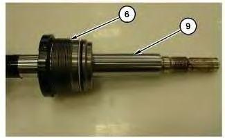
7. Remove cylinder nut (6) from rod end (9).
 g06295398
g06295422
g06296653
g06295398
g06295422
g06296653
Illustration 10 g06295640
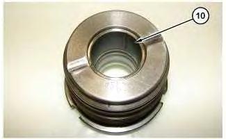
Illustration 11
Illustration 12
 g06295645
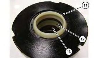
8. Remove bushing (10). Remove outer seal (11), inner seal (12), and O-ring seal (13).
g06295654
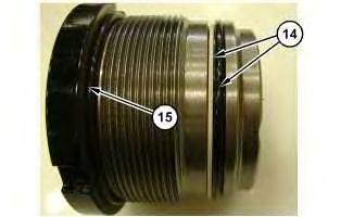
9. Remove O-ring seal and backup ring (14). Remove O-ring seal (15).
g06295645
8. Remove bushing (10). Remove outer seal (11), inner seal (12), and O-ring seal (13).
g06295654
9. Remove O-ring seal and backup ring (14). Remove O-ring seal (15).
Shutdown SIS
Previous Screen
Product: MINI HYD EXCAVATOR
Model: 302CR MINI HYD EXCAVATOR RHM
Configuration: 302 CR Mini Hydraulic Excavator RHM00001-UP (MACHINE) POWERED BY C1.1 Engine
Disassembly and Assembly
Blade Cylinder - Assemble
SMCS - 7562-016-BG
Assembly Procedure
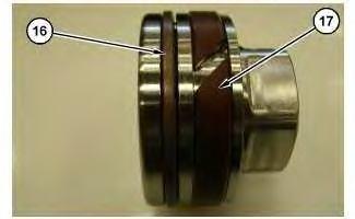
1. Install seal (16) and spacer (17).
2. Install O-ring seal and backup ring (14). Install O-ring seal (15).
Illustration 2 g06295654
Illustration 3 g06295640
Illustration 4 g06295645
3. Install bushing (10). Install O-ring seal (13). Install inner seal (12), and outer seal (11).
4. Install cylinder nut (6) onto rod end (9). Apply oil on seals and rod end for assembly.
5. Mount the rod end onto Tooling (A). Install piston (8). Use Tooling (D) to tighten piston (8). Tighten piston (8) to a torque of 400 ± 20 N·m (295 ± 15 lb ft).
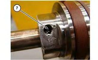 Illustration 5
g06296653
Illustration 6
g06295422
Illustration 7
g06295757
Illustration 5
g06296653
Illustration 6
g06295422
Illustration 7
g06295757
Install ball and set screw (7). Tighten set screw (7) to a torque of 17 ± 2 N·m (150 ± 18 lb in). Stake set screw in place once torque is applied.
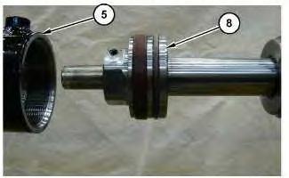
6. Mount barrel end of cylinder (5) on Tooling (A).
Align barrel assembly (5) and the rod assembly for installation. Apply hydraulic oil inside barrel assembly and on piston (8).
Install the piston and rod assembly inside the barrel assembly.
Illustration 8 g06319794 Illustration 9 g06295798Illustration 10 g06295383
Illustration 11
7. Install cylinder nut (6) into barrel assembly (5). Apply hydraulic oil to seals before installation.
Use Tooling (C) to tighten cylinder nut (6) to a torque of 226 N·m (167 lb ft).
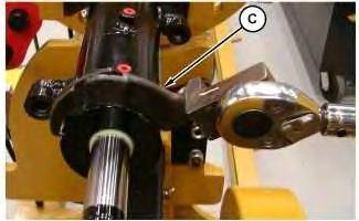
Illustration 12 g06295269
Illustration 13 g06295274
8. Install seals (1) into barrel end of blade cylinder (2). Install seals (3) into rod end of blade cylinder (4).
End By:
a. Install blade cylinder.
Shutdown SIS
Previous Screen
Product: MINI HYD EXCAVATOR
Model: 302CR MINI HYD EXCAVATOR RHM
Configuration: 302 CR Mini Hydraulic Excavator RHM00001-UP (MACHINE) POWERED BY C1.1 Engine
Disassembly and Assembly
301.5,301.6,301.7,301.8,302 Mini Hydraulic Excavator Machine Systems
Blade - Remove and Install
SMCS - 6060-010
Removal Procedure
Start By:
a. Remove blade cylinder
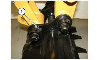
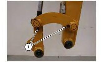
1. Place suitable blocking under blade assembly. Remove bolts (1) and pin assemblies (2).
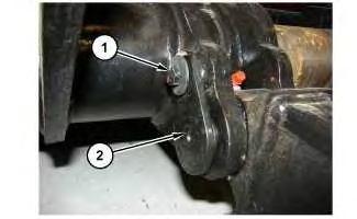
Illustration 2 g06310444
Illustration 3
g06310445
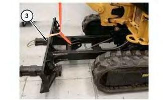
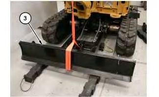
2. Attach strap and a suitable lifting device around blade assembly (3). The weight of blade assembly (3) is approximately 68 kg (150 lb). Remove blade assembly (3).
Installation Procedure
1. Install blade assembly (3) in the reverse order of removal.
End By:
a. Install blade cylinder
Copyright 1993 - 2020 Caterpillar Inc.
All Rights Reserved.
Private Network For SIS Licensees.
Shutdown SIS
Previous Screen
Product: MINI HYD EXCAVATOR
Model: 302CR MINI HYD EXCAVATOR RHM
Configuration: 302 CR Mini Hydraulic Excavator RHM00001-UP (MACHINE) POWERED BY C1.1 Engine
Disassembly and Assembly
301.5,301.6,301.7,301.8,302 Mini Hydraulic Excavator Machine Systems
Bucket - Remove and Install
SMCS - 6001-010; 6101-010
Removal Procedure
1. Lower bucket to the ground.
Illustration 1
1. Remove retainer bolts (1).
Installation Procedure
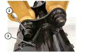 Illustration 2
g06306014
2. Remove pins (2) from bucket linkage and stick. Remove bucket (3).
Illustration 3
g06306014
1. Position the stick over the bucket (3). Install pins (2) through the bucket linkage and the stick.
Illustration 4
g06306012
Illustration 2
g06306014
2. Remove pins (2) from bucket linkage and stick. Remove bucket (3).
Illustration 3
g06306014
1. Position the stick over the bucket (3). Install pins (2) through the bucket linkage and the stick.
Illustration 4
g06306012
Shutdown SIS
Previous Screen
Product: MINI HYD EXCAVATOR
Model: 302CR MINI HYD EXCAVATOR RHM
Configuration: 302 CR Mini Hydraulic Excavator RHM00001-UP (MACHINE) POWERED BY C1.1 Engine
Disassembly and Assembly
301.5,301.6,301.7,301.8,302 Mini Hydraulic Excavator Machine Systems
Bucket - Remove
SMCS - 6101-011
Removal Procedure
1. Lower bucket to the ground.
Illustration 1
1. Remove retainer bolts (1).
Installation Procedure
Illustration 2
g06306014
2. Remove pins (2) from bucket linkage and stick. Remove bucket (3).
Illustration 3
g06306014
1. Position the stick over the bucket (3). Install pins (2) through the bucket linkage and the stick.
Illustration 4
g06306012
Suggest:
If the above button click is invalid.
Please download this document first, and then click the above link to download the complete manual.
Thank you so much for reading

Shutdown SIS
Previous Screen
Product: MINI HYD EXCAVATOR
Model: 302CR MINI HYD EXCAVATOR RHM
Configuration: 302 CR Mini Hydraulic Excavator RHM00001-UP (MACHINE) POWERED BY C1.1 Engine
Disassembly and Assembly
301.5,301.6,301.7,301.8,302 Mini Hydraulic Excavator Machine Systems
Bucket Linkage - Remove and Install
SMCS - 6513-010
Removal Procedure
Start By:
a. Remove Bucket
1.