Shutdown SIS
Previous Screen
Product: MINI HYD EXCAVATOR
Model: 301.8 MINI HYD EXCAVATOR H8X
Configuration: 301.8 Mini Hydraulic Excavator H8X00001-UP (MACHINE) POWERED BY C1.1 Engine
Disassembly and Assembly
301.5,301.6,301.7,301.8,302 Mini Hydraulic Excavator Machine Systems
Blade Cylinder - Assemble

SMCS - 7562-016-BG
Assembly Procedure
Table 1
Required Tools
1. Install seal (16) and spacer (17).
2. Install O-ring seal and backup ring (14). Install O-ring seal (15).
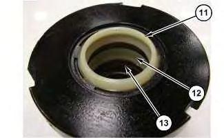
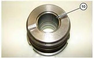
 Illustration 2 g06295654
Illustration 3 g06295640
Illustration 4 g06295645
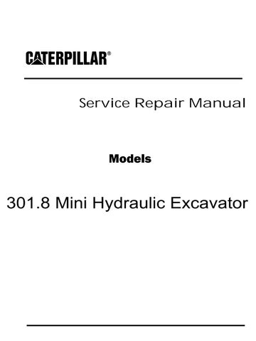
3. Install bushing (10). Install O-ring seal (13). Install inner seal (12), and outer seal (11).
Illustration 2 g06295654
Illustration 3 g06295640
Illustration 4 g06295645
3. Install bushing (10). Install O-ring seal (13). Install inner seal (12), and outer seal (11).
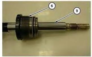
4. Install cylinder nut (6) onto rod end (9). Apply oil on seals and rod end for assembly.
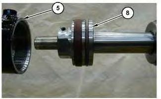
5. Mount the rod end onto Tooling (A). Install piston (8). Use Tooling (D) to tighten piston (8). Tighten piston (8) to a torque of 400 ± 20 N·m (295 ± 15 lb ft).
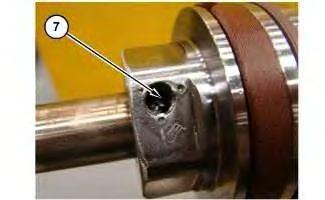
 Illustration 5
g06296653
Illustration 6
g06295422
Illustration 7
g06295757
Illustration 5
g06296653
Illustration 6
g06295422
Illustration 7
g06295757
Install ball and set screw (7). Tighten set screw (7) to a torque of 17 ± 2 N·m (150 ± 18 lb in). Stake set screw in place once torque is applied.
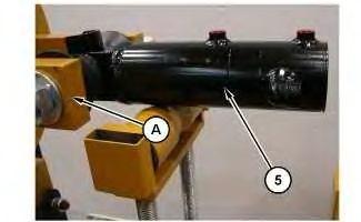
6. Mount barrel end of cylinder (5) on Tooling (A).
Align barrel assembly (5) and the rod assembly for installation. Apply hydraulic oil inside barrel assembly and on piston (8).
Install the piston and rod assembly inside the barrel assembly.
Illustration 8 g06319794 Illustration 9 g06295798Illustration 10 g06295383
Illustration 11
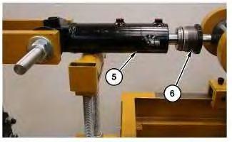
7. Install cylinder nut (6) into barrel assembly (5). Apply hydraulic oil to seals before installation.
Use Tooling (C) to tighten cylinder nut (6) to a torque of 226 N·m (167 lb ft).
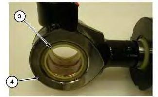
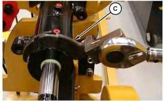
Illustration 12 g06295269
Illustration 13 g06295274
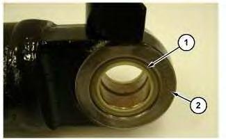
8. Install seals (1) into barrel end of blade cylinder (2). Install seals (3) into rod end of blade cylinder (4).
End By:
a. Install blade cylinder.
Shutdown SIS
Previous Screen
Product: MINI HYD EXCAVATOR
Model: 301.8 MINI HYD EXCAVATOR H8X
Configuration: 301.8 Mini Hydraulic Excavator H8X00001-UP (MACHINE) POWERED BY C1.1 Engine
Disassembly and Assembly
301.5,301.6,301.7,301.8,302 Mini Hydraulic Excavator Machine Systems
Blade - Remove and Install
SMCS - 6060-010
Removal Procedure
Start By:
a. Remove blade cylinder
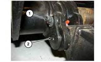
Illustration 1
1. Place suitable blocking under blade assembly. Remove bolts (1) and pin assemblies (2).
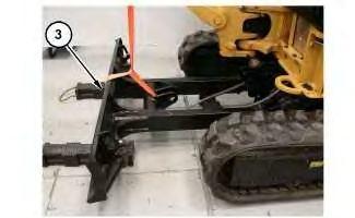
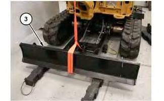
Illustration 2 g06310444
Illustration 3
g06310445
2. Attach strap and a suitable lifting device around blade assembly (3). The weight of blade assembly (3) is approximately 68 kg (150 lb). Remove blade assembly (3).
Installation Procedure
1. Install blade assembly (3) in the reverse order of removal.
End By:
a. Install blade cylinder
Copyright 1993 - 2020 Caterpillar Inc.
All Rights Reserved.
Private Network For SIS Licensees.
Sun Mar 8 19:45:12
Shutdown SIS
Previous Screen
Product: MINI HYD EXCAVATOR
Model: 301.8 MINI HYD EXCAVATOR H8X
Configuration: 301.8 Mini Hydraulic Excavator H8X00001-UP (MACHINE) POWERED BY C1.1 Engine
Disassembly and Assembly
301.5,301.6,301.7,301.8,302 Mini Hydraulic Excavator Machine Systems
Bucket - Remove and Install
SMCS - 6001-010; 6101-010
Removal Procedure
1. Lower bucket to the ground.
Illustration 1
1. Remove retainer bolts (1).

Installation Procedure
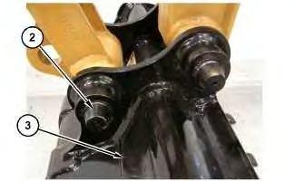 Illustration 2
g06306014
2. Remove pins (2) from bucket linkage and stick. Remove bucket (3).
Illustration 3
g06306014
1. Position the stick over the bucket (3). Install pins (2) through the bucket linkage and the stick.
Illustration 4
g06306012
Illustration 2
g06306014
2. Remove pins (2) from bucket linkage and stick. Remove bucket (3).
Illustration 3
g06306014
1. Position the stick over the bucket (3). Install pins (2) through the bucket linkage and the stick.
Illustration 4
g06306012
Shutdown SIS
Previous Screen
Product: MINI HYD EXCAVATOR
Model: 301.8 MINI HYD EXCAVATOR H8X
Configuration: 301.8 Mini Hydraulic Excavator H8X00001-UP (MACHINE) POWERED BY C1.1 Engine
Disassembly and Assembly
301.5,301.6,301.7,301.8,302 Mini Hydraulic Excavator Machine Systems
Bucket - Remove
SMCS - 6101-011
Removal Procedure
1. Lower bucket to the ground.
Illustration 1
1. Remove retainer bolts (1).
Installation Procedure
Illustration 2
g06306014
2. Remove pins (2) from bucket linkage and stick. Remove bucket (3).
Illustration 3
g06306014
1. Position the stick over the bucket (3). Install pins (2) through the bucket linkage and the stick.
Illustration 4
g06306012
Shutdown SIS
Previous Screen
Product: MINI HYD EXCAVATOR
Model: 301.8 MINI HYD EXCAVATOR H8X
Configuration: 301.8 Mini Hydraulic Excavator H8X00001-UP (MACHINE) POWERED BY C1.1 Engine
Disassembly and Assembly
301.5,301.6,301.7,301.8,302 Mini Hydraulic Excavator Machine Systems
Bucket Linkage - Remove and Install

SMCS - 6513-010
Removal Procedure
Start By:
a. Remove Bucket
1. Remove retainer bolts (1).
Installation Procedure
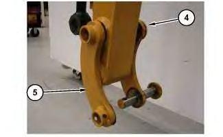
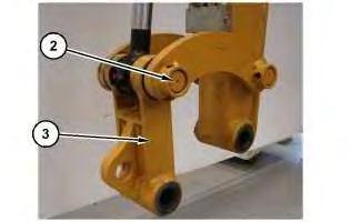 Illustration 2 g06306893
2. Remove pin (2). Remove link assembly (3).
Illustration 3 g06306899
3. Remove pin (4) and links (5).
Illustration 4 g06306899
1. Install links (5) and pin (4) on the stick.
Illustration 2 g06306893
2. Remove pin (2). Remove link assembly (3).
Illustration 3 g06306899
3. Remove pin (4) and links (5).
Illustration 4 g06306899
1. Install links (5) and pin (4) on the stick.
2. Position link assembly (3) along with pin (2) along with the cylinder, on the stick.
Illustration 6 g06306848
3. Install retainer bolts (1). Use 2 nuts to lock retainer bolts (1) in place.
End By:
a. Install Bucket
Shutdown SIS
Previous Screen
Product: MINI HYD EXCAVATOR
Model: 301.8 MINI HYD EXCAVATOR H8X
Configuration: 301.8 Mini Hydraulic Excavator H8X00001-UP (MACHINE) POWERED BY C1.1 Engine
Disassembly and Assembly
301.5,301.6,301.7,301.8,302 Mini Hydraulic Excavator Machine Systems
Bucket Cylinder - Remove and Install
SMCS - 5457-010-G1
Removal Procedure
Start By:
a. Disconnect Bucket Linkage
b. Relieve System Pressure
Cylinders equipped with lock valves can remain pressurized for very long periods of time, even with the hoses removed.
Failure to relieve pressure before removing a lock valve or disassembling a cylinder can result in personal injury or death.
Ensure all pressure is relieved before removing a lock valve or disassembling a cylinder.
Personal injury can result from hydraulic oil pressure and hot oil.
Hydraulic oil pressure can remain in the hydraulic system after the engine has been stopped. Serious injury can be caused if this pressure is not released before any service is done on the hydraulic system.
Make sure all of the work tools have been lowered to the ground, and the oil is cool before removing any components or lines. Remove the oil filler cap only when the engine is stopped, and the filler cap is cool enough to touch with your bare hand.
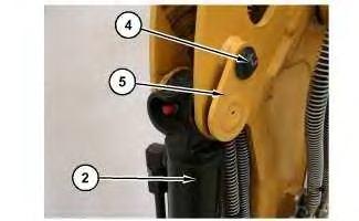
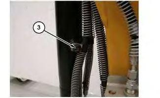
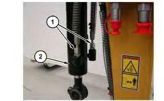 Illustration 1
g06306937
Illustration 2
g06306978
1. Disconnect hose assemblies (1) from bucket cylinder (2). Remove clamps (3).
Illustration 1
g06306937
Illustration 2
g06306978
1. Disconnect hose assemblies (1) from bucket cylinder (2). Remove clamps (3).
Suggest:
If the above button click is invalid.
Please download this document first, and then click the above link to download the complete manual.
Thank you so much for reading

Illustration 3
2. Remove bolt (4), pin assembly (5), and bucket cylinder (2).
Installation Procedure
Illustration 4
1. Position bucket cylinder (2) in place on the stick. Install pin assembly (5) and bolt (4).
Illustration 5
2. Attach hose assemblies (2) to bucket cylinder (2).
End By:
a. Connect the bucket linkage assembly.
Copyright 1993 - 2020 Caterpillar Inc.
All Rights Reserved.
Sun
g06306982 g06306982 g06306937