Service Repair Manual Models
301.7CR Mini Hydraulic Excavator
Shutdown SIS
Previous Screen
Product: MINI HYD EXCAVATOR
Model: 301.7CR MINI HYD EXCAVATOR JH7
Configuration: 301.7CR Mini Hydraulic Excavator JH700001-UP (MACHINE) POWERED BY C1.1 Engine
Disassembly and Assembly
301.5,301.6,301.7,301.8,302 Mini Hydraulic Excavator Machine Systems
Boom Cylinder - Disassemble
SMCS - 5456-015
Disassembly Procedure
Table 1
Required Tools
Start By:
a. Remove boom cylinder.
1. Remove seals (1) from barrel end of boom cylinder (2). Remove seals (3) from rod end of boom cylinder (4).
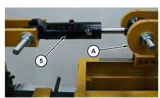
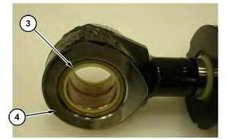
 Illustration 1
g06328511
Illustration 2 g06328514
Illustration 3
g06328699
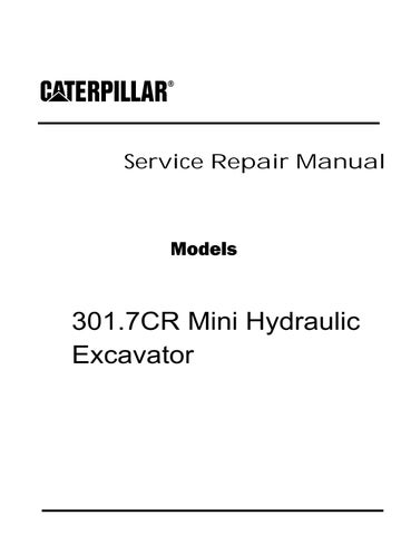
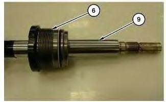
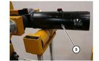
2. Mount boom cylinder (5) into Tooling (A).
Illustration 1
g06328511
Illustration 2 g06328514
Illustration 3
g06328699
2. Mount boom cylinder (5) into Tooling (A).
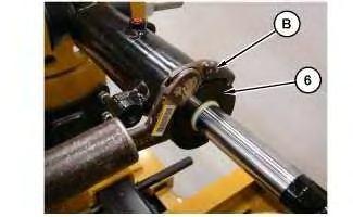
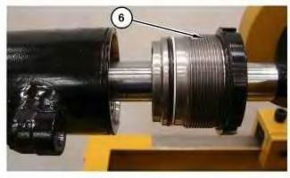
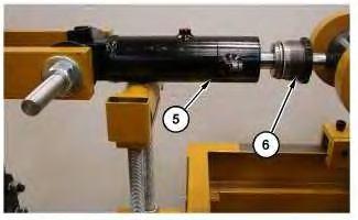 Illustration 4
g06328345
3. Use Tooling (B) to loosen cylinder nut (6).
Illustration 5
g06327540
Illustration 6
g06328403
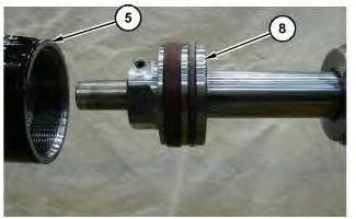
4. Remove cylinder nut (6) from cylinder barrel (5). Place support under barrel end of cylinder (5).
Illustration 4
g06328345
3. Use Tooling (B) to loosen cylinder nut (6).
Illustration 5
g06327540
Illustration 6
g06328403
4. Remove cylinder nut (6) from cylinder barrel (5). Place support under barrel end of cylinder (5).
Illustration 7
5. Back the cylinder bench out to remove rod end (9) from the cylinder barrel. Remove set screw and ball (7) from piston (8).
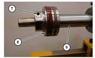
Illustration 8
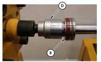
6. Use Tooling (D) to remove piston (8).
Illustration 9
7. Remove cylinder nut (6) from rod end (9).
 g06295398
g06295422
g06296653
g06295398
g06295422
g06296653
Illustration 10 g06295640
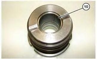
Illustration 11
Illustration 12
 g06295645
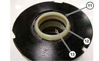
8. Remove bushing (10). Remove outer seal (11), inner seal (12), and O-ring seal (13).
g06295654
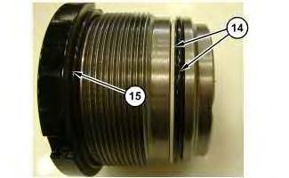
9. Remove O-ring seal and backup ring (14). Remove O-ring seal (15).
g06295645
8. Remove bushing (10). Remove outer seal (11), inner seal (12), and O-ring seal (13).
g06295654
9. Remove O-ring seal and backup ring (14). Remove O-ring seal (15).
Shutdown SIS
Previous Screen
Product: MINI HYD EXCAVATOR
Model: 301.7CR MINI HYD EXCAVATOR JH7
Configuration: 301.7CR Mini Hydraulic Excavator JH700001-UP (MACHINE) POWERED BY C1.1 Engine
Disassembly and Assembly
301.5,301.6,301.7,301.8,302 Mini Hydraulic Excavator Machine Systems
Boom Cylinder - Assemble
SMCS - 5456-016
Assembly Procedure
Table 1
Required Tools
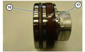
1. Install seal (16) and spacer (17).
2. Install O-ring seal and backup ring (14). Install O-ring seal (15).
Illustration 2 g06295654
Illustration 3 g06295640
Illustration 4 g06295645
3. Install bushing (10). Install O-ring seal (13). Install inner seal (12), and outer seal (11).
4. Install cylinder nut (6) onto rod end (9). Apply oil on seals and rod end for assembly.
5. Mount the rod end onto Tooling (A). Install piston (8). Use Tooling (D) to tighten piston (8). Tighten piston (8) to a torque of 500 ± 25 N·m (370 ± 18 lb ft).
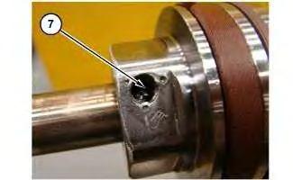 Illustration 5
g06296653
Illustration 6
g06295422
Illustration 7
g06295757
Illustration 5
g06296653
Illustration 6
g06295422
Illustration 7
g06295757
Install ball and set screw (7). Tighten set screw (7) to a torque of 17 ± 2 N·m (150 ± 18 lb in).
6. Mount barrel end of cylinder (5) on Tooling (A).
Align barrel assembly (5) and the rod assembly for installation. Apply hydraulic oil inside barrel assembly and on piston (8).
Install the piston and rod assembly inside the barrel assembly.
Illustration 8 g06328410 Illustration 9 g06328412Illustration 10 g06328403
Illustration 11 g06328413
7. Install cylinder nut (6) into barrel assembly (5). Apply hydraulic oil to seals before installation.
Use Tooling (C) to tighten cylinder nut (6) to a torque of 226 N·m (167 lb ft).
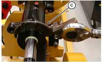
Illustration 12 g06328511
Illustration 13 g06328514
8. Install seals (1) into barrel end of boom cylinder (2). Install seals (3) into rod end of boom cylinder (4).
End By:
a. Install boom cylinder.
Shutdown SIS
Previous Screen
Product: MINI HYD EXCAVATOR
Model: 301.7CR MINI HYD EXCAVATOR JH7
Configuration: 301.7CR Mini Hydraulic Excavator JH700001-UP (MACHINE) POWERED BY C1.1 Engine
Disassembly and Assembly
301.5,301.6,301.7,301.8,302 Mini Hydraulic Excavator Machine Systems
Boom - Remove and Install
SMCS - 6501-010
Removal Procedure
Start By:
a. Remove stick
b. Remove stick cylinder
c. Remove boom cylinder
d. Raise cab
1. Drain hydraulic fluid. Refer to Operation and Maintenance Manual. Hydraulic Oil Drain, for the correct draining and filling procedures.
Illustration 1
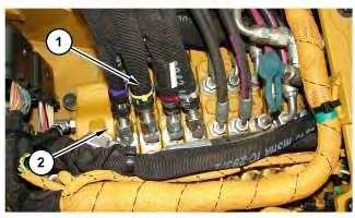
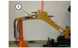
2. Disconnect hydraulic lines (1) that control the boom , stick, and bucket from the main control valve (2).
Illustration 3 g06308625
3. Attach a suitable lifting device to a strap to lift boom assembly (3). The weight of boom assembly (3) is approximately 79 kg (174 lb)
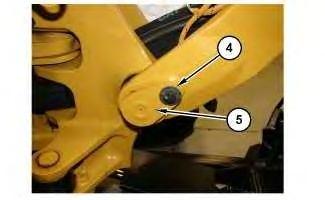
4. Remove retaining bolt (4) from pin assembly (5). Remove pin assembly (5).
5. Carefully feed hydraulic lines (1) through the frame and support assembly. Remove boom assembly (3).
Installation Procedure
1. Install boom assembly (3) in the reverse order of removal.
Copyright 1993 - 2020 Caterpillar Inc. All Rights Reserved. Private Network For SIS Licensees.
Illustration 2 g06308629Shutdown SIS
Previous Screen
Product: MINI HYD EXCAVATOR
Model: 301.7CR MINI HYD EXCAVATOR JH7
Configuration: 301.7CR Mini Hydraulic Excavator JH700001-UP (MACHINE) POWERED BY C1.1 Engine
Disassembly and Assembly
301.5,301.6,301.7,301.8,302 Mini Hydraulic Excavator Machine Systems
Boom Swing Cylinder - Remove and Install
SMCS - 5105-010-BM
Removal Procedure
Cylinders equipped with lock valves can remain pressurized for very long periods of time, even with the hoses removed.
Failure to relieve pressure before removing a lock valve or disassembling a cylinder can result in personal injury or death.
Ensure all pressure is relieved before removing a lock valve or disassembling a cylinder.
Personal injury can result from hydraulic oil pressure and hot oil.
Hydraulic oil pressure can remain in the hydraulic system after the engine has been stopped. Serious injury can be caused if this pressure is not released before any service is done on the hydraulic system.
Make sure all of the work tools have been lowered to the ground, and the oil is cool before removing any components or lines. Remove the oil filler cap only when the engine is stopped, and the filler cap is cool enough to touch with your bare hand.
g06310966
1. Extend boom swing cylinder (1) to full stroke, placing boom and support assembly (2) to the far left side.
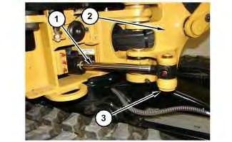
2. Remove pin assembly (3).
g06310972
3. Retract boom swing cylinder (1) completely.
4. Raise cab assembly and lock into place.
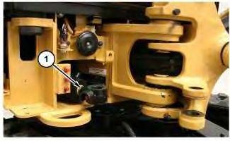 Illustration 1
Illustration 2
Illustration 1
Illustration 2
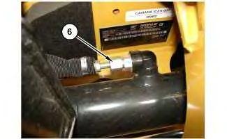
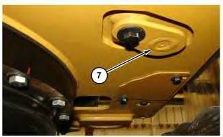 Illustration 3 g06310977
Illustration 4 g06310983
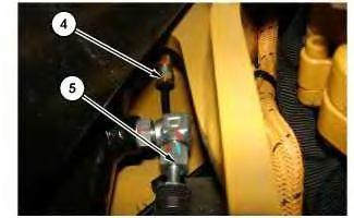
5. Disconnect lube line (4). Disconnect hydraulic fittings (5) and (6).
Illustration 5 g06311287
Illustration 6 g06310972
6. Remove pin assembly (7). Remove boom swing cylinder (1).
Illustration 3 g06310977
Illustration 4 g06310983
5. Disconnect lube line (4). Disconnect hydraulic fittings (5) and (6).
Illustration 5 g06311287
Illustration 6 g06310972
6. Remove pin assembly (7). Remove boom swing cylinder (1).


 Illustration 1
g06295269
Illustration 2
g06295274
Illustration 3
g06327530
2. Mount boom swing cylinder (5) into Tooling (A).
Illustration 1
g06295269
Illustration 2
g06295274
Illustration 3
g06327530
2. Mount boom swing cylinder (5) into Tooling (A).