Service Repair Manual Model 245B SERIES II EXCAVATOR
Shutdown SIS
Previous Screen
Product: EXCAVATOR
Model: 245B EXCAVATOR 1SJ
Configuration: 245B SERIES II EXCAVATOR 1SJ00713-UP (MACHINE) POWERED BY 3406 ENGINE
Disassembly and Assembly
245B EXCAVATOR VEHICLE SYSTEMS
Piston Pump
SMCS - 5070-015; 5070-016; 5070-010
Remove And Install Piston Pump
1. Drain the hydraulic tank oil level below the three piston pump hoses.
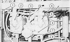
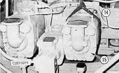
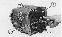
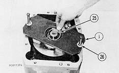
2. Remove four bolts (1) and remove frame (5).
NOTE: Cover all openings in the pumps and the pump lines.
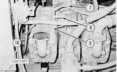
3. Remove oil lines (2), (3), and (4). Disconnect oil lines (6) and (8). Remove elbow (7).
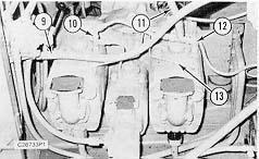
4. Disconnect oil line (9). Disconnect oil line (11) at fittings (10) and (12). Move oil lines (9) and (11) aside. Remove oil line (13).
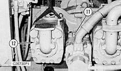
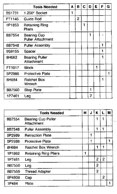
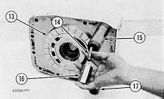
5. Fasten a hoist to front pump (15). Remove two bolts (14) holding the front pump to the pump drive housing and remove front pump (15). Weight of the front piston pump is 935 kg (425 lb).
NOTE: The following steps are for the installation of the front piston pump.
6. Fasten a hoist to front pump (15) and position the front pump on the pump drive. Install two bolts (14).
7. Install oil line (13). Connect oil line (11) at fittings (10) and (12). Connect oil line (9).
8. Install elbow (7) and connect lines (8) and (6). Install lines (2), (3), and (4).
9. Position frame (5) and install four bolts (1).
NOTICE
Do not start engine until pumps are filled with oil.
10. Fill the hydraulic tank to the correct level. See the Operation And Maintenance Manual.
1. Drain the hydraulic tank oil level below the three piston pump hoses.
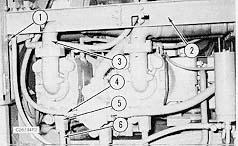
2. Remove four bolts (1) and remove frame (2).
NOTE: Cover all openings in the pumps and pump lines.
3. Remove oil line (3). Disconnect oil lines (4) and (6). Remove elbow (5).
4. Disconnect oil line (10). Remove oil lines (7), (8), and (9).
5. Fasten a hoist to rear pump (12). Remove two bolts (11) holding the rear pump to the pump drive housing and remove rear pump (12). Weight of the rear piston pump is 935 kg (425 lb).
NOTE: The following steps are for the installation of the rear piston pump.
6. Fasten a hoist to rear pump (12) and position the rear pump on the pump drive. Install two bolts (11).
7. Install oil lines (7), (8), and (9). Connect oil line (10).
8. Install elbow (5) and connect lines (6) and (4). Install line (3).
9. Position frame (2) and install four bolts (1).
NOTICE
Do not start engine until pumps are filled with oil.
10. Fill the hydraulic tank to the correct level. See the Operation And Maintenance Manual.
Disassemble Piston Pump (Front Or Rear)
Start By:
 a. remove piston pump (front or rear)
1. Thoroughly clean the outside of the pump.
a. remove piston pump (front or rear)
1. Thoroughly clean the outside of the pump.
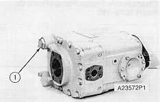
2. Remove plug (1). Remove the shims and the two springs behind plug (1).
3. Remove cover (2). Remove the O-ring seals from the cover.
4. Remove spacers (3) and the sleeve from the servo valve group.
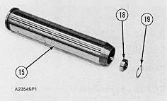
5. Using tooling (C), remove snap ring (10). Remove spacer (9) from sleeve (6).
6. Remove snap ring (11) and stop (8) from spool (7). Remove spool (7) from sleeve (6).
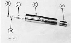
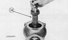
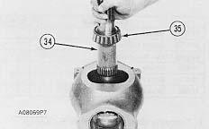
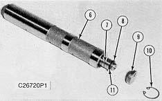
7. Hold the rear of the shaft with a 1 5/8" socket (10) to prevent shaft from turning. Remove the lock nut securing the impeller in place.
8. Remove the impeller (11) key and shims from the pump shaft.
 9. Install guide rods (B) through the head and into the pump body.
10. Remove the head (12) from the body. Remove guide rods (B).
NOTICE
Be extra careful not to damage the highly finished surface on the port plate and the barrel face.
11. Remove the port plate (13) from the head.
12. Remove pistons (14) and (16) from the cartridge (15) for the servo valve.
13. Put identification on the valves and the head as to their location in the head. Remove cartridge (15) for the servo valve. Remove cartridge (17).
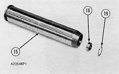
14. Remove snap ring (19) from cartridge (15) with tool (C). Remove insert (18) from cartridge (15).
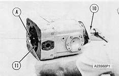
15. Remove piston (22) from cartridge (17).
16. Remove plug (20) and piston (21) from cartridge (17).
17. Remove the O-ring seal (23) from plug (20).
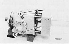
18. Remove the bearing cup from the head with tooling (D). Remove the seal from the shaft bore of the head.
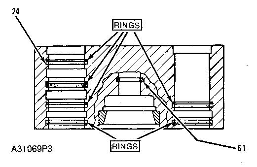
NOTE: Make a note of the location of seals and rings (24) so they will be installed in the correct position in the head.
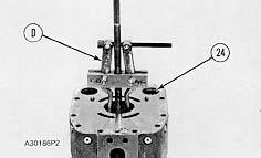
19. Remove the seals and rings (24) from the head.
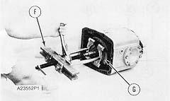
20. Put tool (G) in position against the barrel face. Install tooling (F) and remove the bearing cone from the shaft.
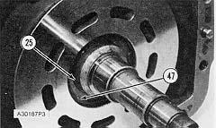
Do not remove the large snap ring (47). Snap ring (47) holds a large spring in the center of the barrel which is under compression. Sudden release of the spring can cause personal injury or damage to the pump.
Typical Example
21. Install tooling (J) with two 1/2" -13 NC forcing screws, nuts and washers. Make sure the wood blocks make contact with the protective plate blocks which is against the barrel face. Tighten nuts (26) evenly to release the pressure against the spiral snap ring (25). Remove spiral snap ring (25).
22. Loosen the nuts evenly and remove tooling (J).
23. Put the protective plate on the barrel face. Oil will hold the plate in position. Turn the pump body to a vertical position on tool (E) as shown.
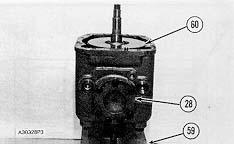
24. Remove the bolts from the two covers (28). Install two 3/8" -16 NC forcing screws and remove the covers and shims. Keep the shims with their respective covers for installation purposes.
25. Remove the bearing cones from the two covers with tooling (F).
26. Install two 3/4" -10 NC forged eyebolts (27), washers and nuts. Fasten a hoist to the pump body. Remove the pump body (29) from the shaft. Weight of body is 45 kg (100 lb).
Typical Example
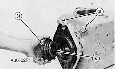
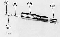
27. Remove two adjustable stop bolts (31) from the body. Remove the O-ring seals from the bolts.
28. Remove retainer (30) from the body. Remove seals (32) and the O-ring seals from the retainer.
NOTICE
Be extra careful not to damage the highly finished surfaces on the pistons.
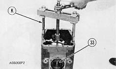 29. Remove bearing cup (33) from the body with tooling (K).
30. Remove shaft (34) from the swashplate and the barrel.
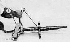
31. Remove bearing cones (35) from the shaft with tooling (F).
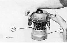
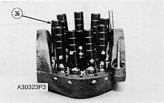
32. Put identification on each piston (36). Put a mark on barrel (37) respective to location of each piston for use during assembly of the pump. Remove the swashplate and the pistons from the barrel as unit.
29. Remove bearing cup (33) from the body with tooling (K).
30. Remove shaft (34) from the swashplate and the barrel.
31. Remove bearing cones (35) from the shaft with tooling (F).
32. Put identification on each piston (36). Put a mark on barrel (37) respective to location of each piston for use during assembly of the pump. Remove the swashplate and the pistons from the barrel as unit.
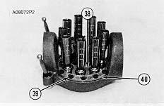
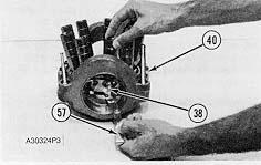
33. Remove bolts (39) and the locks that hold the retraction bearings and shims to the swashplate. Remove retraction bearings (40) and the shims from each side of the swashplate.
34. Remove retraction plate (38). Remove the pistons from the swashplate.
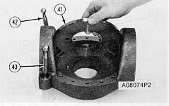
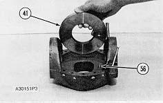
35. Remove the wear plates (41) from the swashplate.
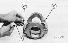
36. Use tool (C) to remove the snap rings that hold links (42) and (43) in the swashplate. Remove the links.
37. Remove the inserts from the swashplate with a hammer and punch.
38. Remove the bearing cups from the swashplate with tooling (L).
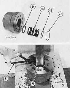
39. Put barrel in position in a press. Put the plastic protective plate on the barrel face for protection of the face from scratches. Put drive plate fromtooling (M) between the press head and spring spacer (46).
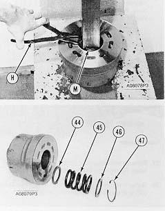
40. Push down on spring (45) to release the pressure against snap ring (47).
41. Remove snap ring (47) with tool (H). Slowly release the compression on spring (45).
42. Remove spacer (46), spring (45) and spacer (44) from the barrel.
Assemble Piston Pump (Front Or Rear)
1. Thoroughly clean all of the parts. Put a small amount of clean hydraulic oil on the parts to be assembled.
Snap ring (47) is used to hold spring (45) in compression. Injury can be the result if the spring pushed the snap ring out of the groove in the pump barrel. Be sure snap ring (47) is completely engaged in the groove in the pump barrel before the press is released.
3. Put the barrel in position in a press. Put the plastic protective plate from tooling (M) on the barrel face. Put drive plate from tooling (M) between the press head and spacer (46). Push down on spring (45) and install snap ring (47) with tooling (H).
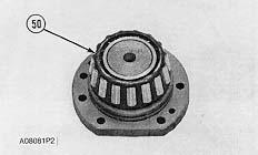
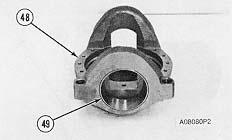
4. Lower the temperature of bearing cups (49). Install the bearing cups in swashplate (48).
 2. Install spacer (44), spring (45) and spacer (46) in barrel.
5. Raise bearing cones (50) from the two covers in oil to a maximum temperature of 120°C (250° F). Install the cones on the covers.
Typical Example
6. Install O-ring seals on bolts (31). Install the locknuts that hold the bolts.
7. Lower the temperature of bearing cup (51) and install the cup in the pump body.
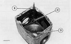
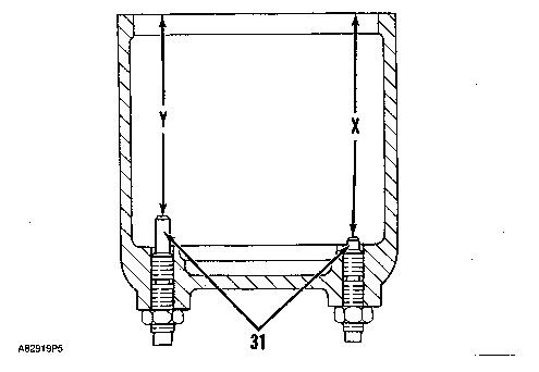
8. Install tool (N) on the pump body and bolts (31).
9. Turn bolts (31) clockwise to decrease the dimension and counterclockwise to increase the dimension. Measure the distance between the top of the pump body and the end of bolts (31).
10. Dimension (Y) must be 181.01 ± 0.13 mm (7.125 ± .005 in). Dimension (X) must be 212.1 ± 0.13 mm (8.350 ± .005 in).
11. Hold the bolts as the locknuts are tightened. Tighten the locknuts to a torque of 200 ± 25 N·m (150 ± 18 lb ft).
12. Raise bearing cone (35) in oil to a maximum temperature of 120°C (250°F). Install bearing cone on the shaft.
NOTICE
Be sure the bearing cone (35) is tight against the shoulder on the shaft.
13. Install shaft (34) in the swashplate.
Typical Example
14. Install the shaft and swashplate in the pump body.
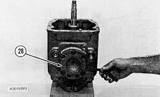
15. Install one of the covers with a 0.38 mm (.015 in) of shims and the O-ring seal. Install the bolts and lockwashers that hold the cover in place. Tighten the bolts to a torque of 43.4 N·m (32 lb ft).
16. Install opposite cover (28) without an O-ring seal, lockwashers or shims. Install three bolts in the cover as shown and tighten to a torque of 4.52 N·m (40 lb in).
NOTE: Do not put total torque on one bolt before the other bolts are tightened. Tighten each bolt 1.13 N·m (10 lb in) at a time in a clockwise direction. While the bolts are tightened turn the swashplate between the stops.
17. Measure the gap between the cover and body with a feeler gauge at the three bolt locations.
18. Install shims that are the same thickness as the average gap measured plug 0.00-0.13 mm (.000 -.005 in).
NOTE: If the thickness of the shims is less than 0.00-0.13 mm (.005 in) or more than 0.64 mm (.025 in), add the thickness of the shims for bother covers. Divide the total thickness of the shims evenly under each cover.
19. Remove the covers and install the correct thickness of shims on each cover and the O-ring seal on cover (28). Install the covers. Tighten the bolts for the cover to a torque of 43.4 N·m (32 lb ft).
20. After the covers are installed, be sure that the swashplate will turn freely between the stops and does not make contact with any part of the pump.
21. Do the following procedure when a replacement of the shaft, head, or bearing is made:
NOTE: Do not install the barrel assembly or pistons for this procedure.
a. Raise the bearing cones to a maximum temperature of 120°C (250°F).
b. Install bearing cones (55) and (35) on shaft and bearing cups (53) and (33) in body and head. Be sure that cups and cones are completely against their respective shoulders.
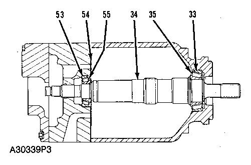
c. Install shaft (34) in the body.
d. Install the head and one gasket (54) on the body. Tighten the head bolts.
e. Put tool (R) in position to measure the end play of shaft (34).
f. Pull on the shaft, turn the shaft in a clockwise and counterclockwise direction 40° to put the bearing against their seats.
g. Turn the indicator to zero while the shaft is turned.
h. Push on the shaft, turn the shaft in a clockwise and counterclockwise direction 40°. If the shaft end play is 0.03 to 0.36 mm (.001 to 0.14 in) go to Step 22. If end play is less than 0.03 mm (.001 in), do Steps i through m.
i. Remove the head bolts. Remove the head and install the other gasket (54). Tighten the head bolts.
j. Pull on the shaft, turn the shaft clockwise and counterclockwise direction 40°. Turn the indicator to zero.
k. Push on the shaft and turn it in a clockwise and counterclockwise direction 40°.
l. Read the indicator while the shaft is turned. Be sure the indicator is at the same point of contact as before. The indicator must show at least 0.15mm (.006 in) of end play.
m. Remove one gasket. A preload of 0.03 mm (.001 in) is the maximum permitted. Go to Step 22.
22. Remove the head, gasket and shaft from the pump body.
23. Use tooling (F) to remove bearing cone (55) from the impeller end of the pump shaft.
24. Install the inserts and links (42) and (43) in the swashplate. Use tool (P) to install the snap rings that hold the links in place.
25. Install wear plate (41) in the swashplate with the dowel (56) in alignment with the hole in the wear plate.
26. Put pistons (36) in position on the wear plate in the same position from which they were moved. Install retraction plate (38).
27. Put the original amount of shims and retraction bearing (40) in position on the swashplate. Install the bolts.
28. Measure the clearance between the piston slippers and the wear plate with a feeler gauge (57). The clearance must be between all slippers and the wear plate must be 0.08 ± 0.03 mm (.003 ± .001). Add or subtract shims if the clearance is not correct.
29. Install the pistons and swashplate as a unit on barrel (37) respective to the marks put on the barrel and pistons at disassembly.
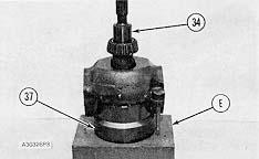
30. Put the barrel and swashplate in position on tooling (E) as shown.
31. Install shaft (34) in the swashplate and barrel.
Typical Example
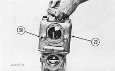
32. Put pump body (29) in position over the shaft, swashplate and barrel. Make sure that plugs (58) are on the same side of the swashplate as the links.
Typical Example
33. Turn body (29) over carefully. Do not damage the barrel face.
34. Install two 1/2" -13 NC forged eyebolts in the pump body. Fasten a hoist and put the body on the block (59) of tooling (E). Put protective plate (60) of tooling (E) on the barrel face to give it protection from damage.
35. Install the correct thickness of shims on covers (28). Install the O-ring seals on the covers. Put oil on the seals. Put the covers in position on the body. Install the bolts. Tighten the bolts to a torque of 43.4 N·m (32 lb ft).
Typical Example
36. Install tool (J) with two 1/2" -13 NC forcing screws, nuts and washers. Make sure the wood blocks make contact with barrel protective plate (60) on the barrel face. Tighten nuts (26) evenly until spiral snap ring (25) can be installed on the shaft. Install the spiral snap ring on the shaft Loosen the nuts evenly and remove tooling (J).
37. Raise the bearing cone for the shaft to a maximum temperature of 120°C (250°F). Install the bearing cone on the shaft.
38. Install the six rings (24) and the O-ring seals in the head. Put oil on the seals and O-rings.
NOTE: Make sure the rings and seals in the groove nearest the finished face of the head are installed with the rings nearest the finished inside face. The other rings and seals must be installed with the rings nearest the outside of the head.
39. Install seal (61) in the bore for the pump shaft.
40. Install O-ring seal (23) on plug (20).
41. Install pistons (21) and (22) and plug (20) in cartridge (17).
42. Install spool (7) in valve (6). Install stop (8) and snap ring (11) on spool (7).
43. Install spacer (9) and snap ring (10). Use tool (P) to install snap ring (10).
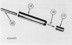
44. Install insert (18) in valve (15). Install snap ring (19) that holds the insert in place.
45. Install valve (62) in servo valve (15).
46. Install pistons (14) and (17) in valve (15).
47. Install the servo valve (15) in the head. Install (cartridge) valve (17) in the head.
48. Put a small amount of clean hydraulic oil on the finished face of the head. Make sure the dowels for the port plate are installed in the head. Install the port plate (13) on the head.
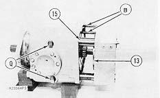
49. Install guide rods (B) in the pump body.
50. Remove the two plugs in the pump body. Install tools (Q) through the plug holes and on to the swashplate links as shown.
51. Install the correct number of gaskets on head as found in Step 28. If Step 28 was not used, install the number of gaskets that were on the head when it was disassembled.
52. Put the head in position on guide rods (B).
53. Move the head toward the body. Use tools (Q) to put the swashplate links in alignment with the pistons in servo valve (15) and valve (17).
Suggest:
If the above button click is invalid.
Please download this document first, and then click the above link to download the complete manual.
Thank you so much for reading

Typical Example
54. Install two bolts and washers (65) to hold the head tightly against the pump body.
55. Remove tools (Q) and install the plugs in the pump body.
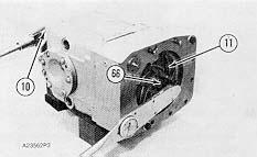
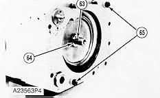
56. Install six shims (64) and key (63) on the pump shaft.
57. Install impeller (11). Hold the rear of shaft with a 1 5/8" socket to prevent shaft from turning. Install the locknut securing the impeller in place. Tighten nut (66) to a torque of 150 ± 20 N·m (111 ± 15 lb ft).
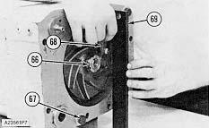
Typical Example
58. Use a bar (69) with a flat surface and a feeler gauge (68) to check the clearance between the impeller and the bar. Check the clearance at three locations around the impeller and the bar. Check the clearance at three locations around the impeller, 120° apart.
59. Use shims (64) as necessary to get a clearance of .044 ± 0.08 mm (0.17 ± .003 in) between the impeller and bar (69).
60. Tighten nut (66) to a torque of 150 ± 20 N·m (111 ± 15 lb ft).
61. Remove the two bolts and washers (67).