235C FRONT SHOVEL
Shutdown SIS
Previous Screen
Product: FRONT SHOVEL
Model: 235C FRONT SHOVEL 4DG
Configuration: 235C EXCAVATOR 4DG00001-UP (MACHINE) POWERED BY 3306 ENGINE
Disassembly and Assembly
3304B and 3306B Engines for Caterpillar Built Machines
Gear Group (Front) - Remove
SMCS - 1206-011
Removal Procedure Table 1
Required Tools
Tool
Start By:
A. Remove the automatic timing advance unit. Refer to Disassembly and Assembly, "Automatic Timing Advance - Remove".
NOTICE
Keep all parts clean from contaminants.
Contaminants may cause rapid wear and shortened component life.
Media Number -SENR5598-09 Publication Date -01/01/2013 Date Updated -25/01/2013 i02107004
Part Number Part Description Qty
Driver Group
A 1P-0510
1
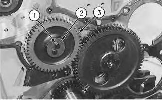
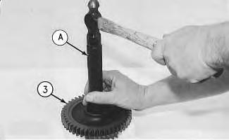
 Illustration 1
g00476414
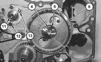
1. Remove bolts (1), plate (2), and fuel pump idler gear (3) .
Illustration 2
g00476416
2. Remove the bearing from fuel pump idler gear (3) with Tooling (A) .
Illustration 3
g00476417
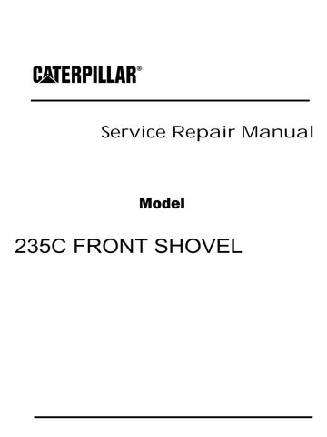
3. Remove bolts (4), plate (5), and camshaft gear (6) .
Illustration 1
g00476414
1. Remove bolts (1), plate (2), and fuel pump idler gear (3) .
Illustration 2
g00476416
2. Remove the bearing from fuel pump idler gear (3) with Tooling (A) .
Illustration 3
g00476417
3. Remove bolts (4), plate (5), and camshaft gear (6) .
Illustration 4 g00476418
4. Remove the bolts that hold shield (7) in position between the fuel pump and the exhaust manifold. Slide the shield backward from the timing cover plate.

5. Remove nuts (8) .
Illustration 5 g00476419
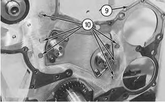
6. Remove bolts (10). Remove timing gear plate (9) and the gasket.
Sun
16:15:15 UTC+0800 2019
Copyright 1993 - 2019 Caterpillar Inc. All Rights Reserved. Private Network For SIS Licensees. Oct 6
Previous Screen
Product: FRONT SHOVEL
Model: 235C FRONT SHOVEL 4DG
Configuration: 235C EXCAVATOR 4DG00001-UP (MACHINE) POWERED BY 3306 ENGINE
Disassembly and Assembly
3304B and 3306B Engines for Caterpillar Built Machines
Gear Group (Front) - Install
SMCS - 1206-012
Installation Procedure Table 1
Required Tools
NOTICE
Keep all parts clean from contaminants.
Contaminants may cause rapid wear and shortened component life.
Shutdown SIS
Note: Check the condition of the gaskets and the O-ring seals. If the gaskets or the O-ring seals are worn or damaged, use new parts for replacement.
1. Clean the old gasket from the contact surfaces of the timing gear plate and the cylinder block. Install a new gasket on the cylinder block. Cut the gasket even with the bottom face of the cylinder block.
Number -SENR5598-09 Publication Date -01/01/2013 Date Updated -25/01/2013
Media
i02107019
Tool Part Number Part Description Qty A 1P-0510 Driver Group 1 B 9S-3263 Thread Lock Compound 1
NOTICE
The bolts that hold the timing gear plate in position on the cylinder block should have a reduced bolt head thickness. The reduced bolt head thickness is needed for clearance for the gears.
2. Ensure that the O-ring seals are in position on the end of the fuel injection pump housing. Put timing gear plate (9) in position on the cylinder block. Install bolts (10) .
3. Install shield (7). Install nuts (8) .
Note: After the timing gear plate is installed, ensure that the rack is free to move in the fuel injection pump housing. The O-ring seal on the drive end of the fuel injection pump housing can hold the rack. This can help prevent free rack movement. Rack movement can be seen through a hole in the timing gear plate just above the mounting of the fuel pump gear. If the rack does not move freely, remove the timing gear plate and check the O-ring seal on the drive end of the fuel injection pump housing.
Illustration 1 g00476419 Illustration 2 g00476418If the rack does not move freely, the engine can over speed and be damaged. Serious personal injury may result.
g01072912
Note: If idler gear shaft (11) for the fuel pump idler gear was removed, use Tooling (B) on the threads of bolts (12) and nut (13) before reinstalling idler gear shaft (11). Tighten bolts (12) and nut (13) to a torque of 50 ± 10 N·m (37 ± 7 lb ft).
4. Put camshaft gear (6) and plate (5) in position on the engine. Align the Mark "C" on the camshaft gear with the Mark "C" on the crankshaft gear. Install bolts (4) and tighten bolts (4) to a torque of 55 ± 7 N·m (41 ± 5 lb ft).
g00476416
5. Use Tooling (A) in order to install the bearing in fuel pump idler gear (3). The end of the bearing must be 3.00 ± 0.25 mm (.118 ± .010 inch) below the face of the hub of the fuel pump idler gear.
Illustration 3 Illustration 46. Ensure that the oil hole in the shaft for fuel pump idler gear (3) is open. Install fuel pump idler gear (3). Put plate (2) in position with the finished side facing toward fuel pump idler gear (3). Apply Tooling (B) on bolts (1). Install bolts (1) that hold fuel pump idler gear (3) in position.
Note: Remove excess Tooling (B) on plate (2). Excess Tooling (B) on plate (2) may flow into the gear bearings. This condition can affect lubrication. Bearing life can also be affected.
End By: Install the automatic timing advance unit. Refer to Disassembly and Assembly, "Automatic Timing Advance - Install".
Copyright 1993 - 2019 Caterpillar Inc.
Illustration 5
g00476414
Private Network For SIS Licensees.
All Rights Reserved.
Sun Oct 6 16:16:11 UTC+0800 2019
Previous Screen
Product: FRONT SHOVEL
Model: 235C FRONT SHOVEL 4DG
Configuration: 235C EXCAVATOR 4DG00001-UP (MACHINE) POWERED BY 3306 ENGINE
Disassembly and Assembly
3304B and 3306B Engines for Caterpillar Built Machines
Housing (Front) - Remove
SMCS - 1151-011
Removal Procedure
Start By:
A. Remove the water pump. Refer to Disassembly and Assembly, "Water Pump - Remove".
B. Remove the crankshaft front seal. Refer to Disassembly and Assembly, "Crankshaft Front Seal - Remove".
NOTICE
Keep all parts clean from contaminants.
Contaminants may cause rapid wear and shortened component life.
NOTICE
Care must be taken to ensure that fluids are contained during performance of inspection, maintenance, testing, adjusting and repair of the product. Be prepared to collect the fluid with suitable containers before opening any compartment or disassembling any component containing fluids.
Refer to Special Publication, NENG2500, "Caterpillar Tools and Shop Products Guide" for tools and supplies suitable to collect and contain fluids on Caterpillar products.
Dispose of all fluids according to local regulations and mandates.
Shutdown SIS
Media Number -SENR5598-09 Publication Date -01/01/2013 Date Updated -25/01/2013
i02107163
1. Remove the bolts that hold the oil pan and the oil pan plate to the front housing. Loosen the remaining bolts that hold the oil pan in position. Put spacers between the cylinder block and the oil pan plate. This must be done in order to prevent damage to the gasket for the oil pan plate.
Note: If the gasket for the oil pan plate is damaged, the oil pan plate must be removed. Refer to Disassembly and Assembly, "Engine Oil Pan Plate - Remove and Install".
2. Remove covers (1) and (2) from the back of the front plate.
3. Remove all bolts (3) that hold front housing (4) in position on the engine. Remove front housing (4) and the gasket from the engine.
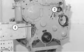
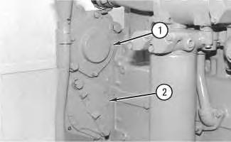 Illustration 1
g00512114
Illustration 2 g00512122
Illustration 1
g00512114
Illustration 2 g00512122
Copyright 1993 - 2019 Caterpillar Inc. All Rights Reserved. Private Network For SIS Licensees. Sun Oct 6 16:17:06 UTC+0800 2019
Previous Screen
Product: FRONT SHOVEL
Model: 235C FRONT SHOVEL 4DG
Configuration: 235C EXCAVATOR 4DG00001-UP (MACHINE) POWERED BY 3306 ENGINE
Disassembly and Assembly
3304B and 3306B Engines for Caterpillar Built Machines
Housing (Front) - Install
SMCS - 1151-012
Installation Procedure
Required Tools
Keep all parts clean from contaminants.
Contaminants may cause rapid wear and shortened component life.
Shutdown SIS

Media Number -SENR5598-09 Publication Date -01/01/2013 Date Updated -25/01/2013 i02107191
Table 1
Tool Part Number Part Description Qty A 3S-6252 Sealant 1
NOTICE
Illustration 1 g00512213
1. Put the gasket and front housing (4) in position on the engine. Install all bolts (3) that hold the front housing to the engine. Tighten bolts (5) to a torque of 23 ± 4 N·m (17 ± 3 lb ft).
Illustration 2 g00512114
2. Put the gasket and cover (1) in position and install the bolts that fasten cover (1) to the front plate. Put the O-ring seal and cover (2) in position and install the bolts that fasten cover (2) to the front plate.
3. Trim the front housing gasket so the gasket is even with the bottom of the cylinder block. Note: If the oil pan plate was removed, install a new gasket and install the oil pan plate. Refer to Disassembly and Assembly, "Engine Oil Pan Plate - Remove and Install".
4. Apply Tooling (A) to the bottom surface of the front housing gasket. Remove the spacers that were installed between the cylinder block and the oil pan plate. Install the bolts that hold the oil pan and the oil pan plate to the front housing. Tighten the remaining bolts that hold the oil pan in position.
Copyright 1993 - 2019 Caterpillar Inc.
All Rights Reserved.
Private Network For SIS Licensees.
Sun Oct 6 16:18:02 UTC+0800 2019
Previous Screen
Product: FRONT SHOVEL
Model: 235C FRONT SHOVEL 4DG
Configuration: 235C EXCAVATOR 4DG00001-UP (MACHINE) POWERED BY 3306 ENGINE
Disassembly and Assembly
3304B and 3306B Engines for Caterpillar Built Machines
Valve Mechanism Cover - Remove and Install
SMCS - 1107-010
3304B Removal Procedure NOTICE
Keep all parts clean from contaminants.
Contaminants may cause rapid wear and shortened component life.
Shutdown SIS
Media Number -SENR5598-09 Publication Date -01/01/2013 Date Updated -25/01/2013 i04880697
Illustration 1 g00590318
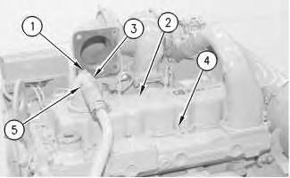
1. Loosen hose clamp (5) and remove the hose from breather cap (3) .
2. Remove bolt (1) and remove breather cap (3) .
3. Remove bolts (4) and the washers that hold valve mechanism cover (2) in position. Remove valve mechanism cover (2) and the gasket.
3306B Removal Procedure NOTICE
Keep all parts clean from contaminants.
Contaminants may cause rapid wear and shortened component life.
1. Remove bolt (1) and breather cap (3) from valve mechanism cover (2) . Remove the O-ring seal from breather cap (3) .
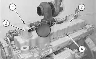
2. Remove bolts (4) and the washers that hold valve mechanism cover (2) in position. Remove valve mechanism cover (2) and the gasket.
3304B Installation Procedure NOTICE
Keep all parts clean from contaminants.
Contaminants may cause rapid wear and shortened component life.
Illustration 2 g00513507
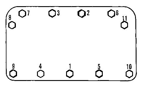 Illustration 3
g00590318
Illustration 4
g00590290
Illustration 5
g00590318
Illustration 3
g00590318
Illustration 4
g00590290
Illustration 5
g00590318
Note: Check the condition of the gasket. If the gasket is worn or damaged, use new parts for replacement.
1. Install a new gasket for valve mechanism cover (2) . Apply 5H-2471 Adhesive on the surfaces of the gasket and valve mechanism cover (2) . Place valve mechanism cover (2) in position on the cylinder head.
2. Install bolts (4) that hold valve mechanism cover (2) . Tighten the bolts in a numerical sequence to a torque of 16 ± 3 N·m (12 ± 2 lb ft).
3. Install the hose on breather cap (3) and tighten hose clamp (5) .
3306B Installation Procedure NOTICE
Keep all parts clean from contaminants.
Contaminants may cause rapid wear and shortened component life.
Note: Check the condition of the gasket and O-ring seals. If the gasket or the O-ring seals are worn or damaged, use new parts for replacement.
1. Install a new gasket for valve mechanism cover (2) . Put valve mechanism cover (2) in position on the cylinder head.
Illustration 6
g00513507
Illustration 7 g00450791
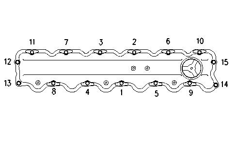
2. Install the washers and bolts (4) that hold valve mechanism cover (2) in position. Tighten the bolts in a numerical sequence to a torque of 16 ± 3 N·m (12 ± 2 lb ft). Use the numerical sequence that is shown in illustration 7.
3. Put the O-ring seal and breather cap (3) in position. Install the washer and bolt (1) . Tighten bolt (1) to a torque of 14 ± 3 N·m (10 ± 2 lb ft). Copyright 1993 - 2019
All
Private
Sun Oct 6 16:18:58 UTC+0800 2019
Caterpillar Inc.
Rights Reserved.
Network For SIS Licensees.
Shutdown SIS
Previous Screen
Product: FRONT SHOVEL
Model: 235C FRONT SHOVEL 4DG
Configuration: 235C EXCAVATOR 4DG00001-UP (MACHINE) POWERED BY 3306 ENGINE
Disassembly and Assembly
3304B and 3306B Engines for Caterpillar Built Machines
Compression Brake - Remove
SMCS - 1119-011
Removal Procedure
Start By:
A. Remove the valve mechanism cover. Refer to Disassembly and Assembly, "Valve Mechanism Cover - Remove and Install".
NOTICE
Keep all parts clean from contaminants.
Contaminants may cause rapid wear and shortened component life. Illustration
Media Number -SENR5598-09 Publication Date -01/01/2013 Date Updated -25/01/2013
i00921540
1
g00471009
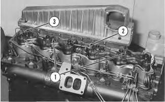
1. Remove four bolts (1). Disconnect wires (2) and (3) .
2. Remove Compression Brake (A) by lifting Compression Brake (A) with one hand. Remove Compression Brake (A) while you hold oil tube (4) in order to ensure that oil tube (4) does not come out of Compression Brake (B) .
3. Remove Compression Brake (B) .
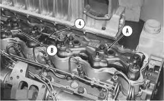
Illustration 2 g00471010
Copyright 1993 - 2019 Caterpillar Inc. All Rights Reserved. Private Network For SIS Licensees. Sun Oct 6 16:19:54 UTC+0800 2019
Shutdown SIS
Previous Screen
Product: FRONT SHOVEL
Model: 235C FRONT SHOVEL 4DG
Configuration: 235C EXCAVATOR 4DG00001-UP (MACHINE) POWERED BY 3306 ENGINE
Disassembly and Assembly
3304B and 3306B Engines for Caterpillar Built Machines
Compression Brake - Disassemble
SMCS - 1119-015
Disassembly Procedure
Start By:
A. Remove the Compression Brake. Refer to Disassembly and Assembly, "Compression Brake - Remove".
NOTICE
Keep all parts clean from contaminants.
Contaminants may cause rapid wear and shortened component life. Illustration
Media Number -SENR5598-09 Publication Date -01/01/2013 Date Updated -25/01/2013
i00921740
1
g00471083
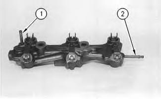
1. Remove oil tubes (1) and (2). Remove the O-ring seals.
Note: If the O-ring seals are worn or damaged, use new parts for replacement.
2. Remove snap ring (7), cup (6), spacer (5), springs (4) and (3) and piston (8) .
3. Remove three retaining rings (13). Remove clip (12), springs (11) and (10) and piston (9) from three locations on the Compression Brake.
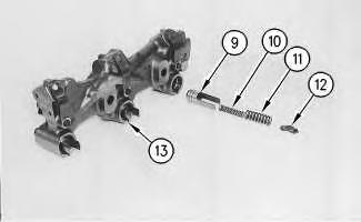
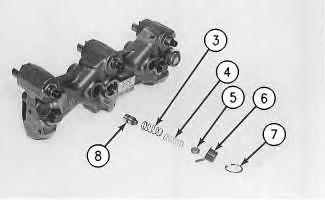 Illustration 2 g00471084
Illustration 3 g00471085
Illustration 2 g00471084
Illustration 3 g00471085
Suggest:
If the above button click is invalid.
Please download this document first, and then click the above link to download the complete manual.
Thank you so much for reading

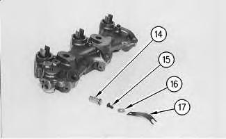
Illustration 4 g00471086
Copyright 1993 - 2019 Caterpillar Inc. All Rights Reserved. Private Network For SIS Licensees. Sun Oct 6 16:20:49 UTC+0800 2019
4. Remove three bolts (15), washers (16), clips (17) and piston (14) .