Service Repair Manual Model 235 EXCAVATOR
Shutdown SIS
Previous Screen
Product: EXCAVATOR
Model: 235 EXCAVATOR 83X
Configuration: 235 EXCAVATOR 83X00444-UP (MACHINE) POWERED BY 3306 ENGINE
Disassembly and Assembly
3304B and 3306B Engines for Caterpillar Built Machines
Exhaust Manifold - Remove and Install
SMCS - 1059-010
Removal Procedure
Start By:
A. Remove the turbocharger. Refer to Disassembly and Assembly, "Turbocharger - Remove".
NOTICE
Keep all parts clean from contaminants.
Contaminants may cause rapid wear and shortened component life.
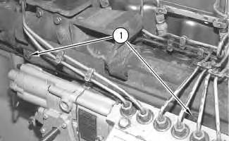
1. Remove two nuts (1), the washers and the heat shield from the exhaust manifold.
2. Remove bolt (3) from the bracket that holds two of the fuel injection lines in position. Loosen nuts (2) and (4) and remove the two fuel injection lines from the engine. Put protective caps on the fuel injectors and put protective caps on the fuel injection pump in order to prevent contamination.
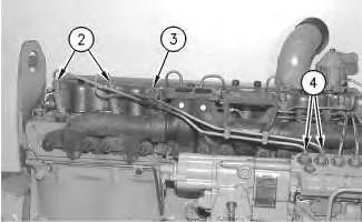
3. Remove the remaining ten exhaust manifold nuts (5) and the large washers. Remove exhaust manifold (6).
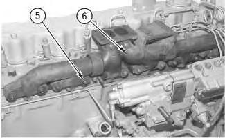 Illustration 2
g00537855
Illustration 3
g00537885
Illustration 2
g00537855
Illustration 3
g00537885
4. Remove three exhaust manifold gaskets (7) from the cylinder head and the twelve exhaust manifold studs, if necessary. Make sure that the position of the two longer studs are marked for proper installation.
Installation Procedure
Table 1
Required Tools
Tool Part Number Description Qty
A 5P-0144 Fuel Line Socket 1
Keep all parts clean from contaminants.
Contaminants may cause rapid wear and shortened component life.
1. If the twelve exhaust manifold studs were removed, apply 5P-3931 Anti-Seize Compound to both ends of the exhaust manifold studs and install the studs in the cylinder head. Make sure that the two longer studs are installed in the correct position. Tighten the studs to a torque of 27 ± 4 N·m (20 ± 3 lb ft).
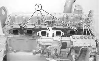 Illustration 5
g00541058
2. Put three exhaust manifold gaskets (7) in position on the cylinder head.
Illustration 6
g00537885
3. Install exhaust manifold (6). Install ten washers and nuts (5). The two longer studs are for the installation of the heat shield. Tighten exhaust manifold nuts (5) to a torque of 47 ± 4 N·m (35 ± 3 lb ft).
Illustration 7
g00537855
Illustration 5
g00541058
2. Put three exhaust manifold gaskets (7) in position on the cylinder head.
Illustration 6
g00537885
3. Install exhaust manifold (6). Install ten washers and nuts (5). The two longer studs are for the installation of the heat shield. Tighten exhaust manifold nuts (5) to a torque of 47 ± 4 N·m (35 ± 3 lb ft).
Illustration 7
g00537855
4. Remove the protective caps from the fuel injectors and the fuel injection pump. Put the fuel injection lines in position and tighten nuts (2) and (4) finger tight. Install bolt (3) in the bracket that holds the fuel injection lines in position. Tighten nuts (3) and (4) with Tool (A) to a torque of 40 ± 7 N·m (30 ± 5 lb ft).
5. Install the two large washers and the spacers on the two remaining exhaust manifold studs. Install heat shield (1) and the remaining two washers and exhaust manifold nuts that fasten heat shield (1) to the exhaust manifold. Tighten the two nuts to a torque of 47 ± 4 N·m (35 ± 3 lb ft).
6. Prime the fuel system. Refer to the Operation and Maintenance Manual, "Fuel systemPrime" topic (Maintenance Section).
End By: Install the turbocharger. Refer to Disassembly and Assembly, "Turbocharger - Install". Copyright 1993 - 2019 Caterpillar Inc.
Illustration 8 g00537836Shutdown SIS
Previous Screen
Product: EXCAVATOR
Model: 235 EXCAVATOR 83X
Configuration: 235 EXCAVATOR 83X00444-UP (MACHINE) POWERED BY 3306 ENGINE
Disassembly and Assembly
3304B and 3306B Engines for Caterpillar Built Machines
Inlet and Exhaust Valves - Remove and Install
SMCS - 1105-010
Removal Procedure Table 1
Required Tools
Start By:
A. Remove the cylinder head. Refer to Disassembly and assembly, "Cylinder Head - Remove".
NOTICE
Keep all parts clean from contaminants.
Contaminants may cause rapid wear and shortened component life.
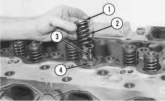
Illustration 1
g00490614
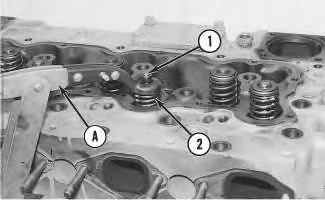
1. Use Tool (A) to compress valve spring (2) and remove valve keepers (1) .
2. Remove Tool (A), the rotocoil, the valve spring and the valve stem oil shield. Remove the valve from the cylinder head. Put identification marks on the valves for installation purposes.
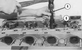
Illustration 2
g00490682
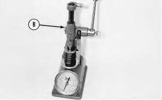
3. Check the valve spring force with Tool (B). Refer to Specifications, "Cylinder Head Valves" for information on the valve springs.
4. Perform Steps 1 through 3 for the remaining inlet and exhaust valves.
Installation Procedure
NOTICE
Keep all parts clean from contaminants.
Contaminants may cause rapid wear and shortened component life.
 1. Lubricate the inlet and exhaust valves with clean engine oil. Install the inlet and exhaust valves in the original location in the cylinder head.
Illustration 3
g00508681
2. Install valves (3), oil shield (4), valve spring (2) and rotocoil (1) in the cylinder head.
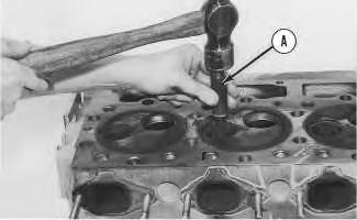
Illustration 4
g00490777
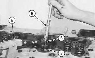
3. Use Tool (A) to compress valve spring (2). Install valve keeper (5) on the valve stem with Tool (B) .
1. Lubricate the inlet and exhaust valves with clean engine oil. Install the inlet and exhaust valves in the original location in the cylinder head.
Illustration 3
g00508681
2. Install valves (3), oil shield (4), valve spring (2) and rotocoil (1) in the cylinder head.
Illustration 4
g00490777
3. Use Tool (A) to compress valve spring (2). Install valve keeper (5) on the valve stem with Tool (B) .
The valve keepers can be thrown from the valve when the valve spring compressor is released. Ensure that the valve keepers are properly installed on the valve stem. To help prevent personal injury, keep away from the front of the valve keepers and valve springs during the installation of the valves.
4. Carefully remove Tool (A). Strike the top of the valve with a soft faced hammer in order to ensure that the valve keepers are properly installed.
5. Repeat Steps 3 through 4 for the remaining inlet and exhaust valves.
End By: Install the cylinder head. Refer to Disassembly and Assembly, "Cylinder Head - Remove and Install".
Copyright 1993 - 2019 Caterpillar Inc. All Rights Reserved. Private Network For SIS Licensees.
Previous Screen
Product: EXCAVATOR
Model: 235 EXCAVATOR 83X
Configuration: 235 EXCAVATOR 83X00444-UP (MACHINE) POWERED BY 3306 ENGINE
Disassembly and Assembly
3304B and 3306B Engines for Caterpillar Built Machines
Shutdown SIS
Inlet and Exhaust Valve Guides - Remove and Install
SMCS - 1104-010
Removal Procedure Table 1
Required Tools
Tool
A 9U-7349
Start By:
1
A. Remove the inlet and exhaust valves. Refer to Disassembly and Assembly, "Inlet and Exhaust Valves - Remove and Install".
NOTICE
Keep all parts clean from contaminants.
Contaminants may cause rapid wear and shortened component life.
g00490787
1. Use Tool (A) to remove the inlet and exhaust valve guides from the cylinder head.
2. Repeat Step 1 for the remaining inlet and exhaust valve guides.
Installation Procedure Table 2
Required Tools
A
B 9U-6954 Valve Guide Collar 1
NOTICE
Keep all parts clean from contaminants.
Contaminants may cause rapid wear and shortened component life.
Illustration 2
g00490790
1. Put clean engine oil on the outside diameter of the valve guide. Install the valve guide with Tool (A) and Tool (B), as shown.
Illustration 3
g00508601
2. Dimension (X) from the top of the valve guide to the cylinder head must be 22.23 ± 0.25 mm (0.875 ± 0.010 inch). For more information on the inlet and exhaust valve guides, refer to Specifications, "Cylinder Head Valves".
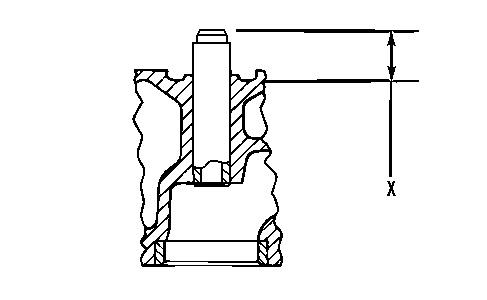
Note: In order to help prevent damage to the valve guides, Tool (B) must be used during installation.
3. Repeat Steps 1 and 2 for the remaining inlet and exhaust valve guides.
End By: Install the inlet and exhaust valves. Refer to Disassembly and Assembly, "Inlet and Exhaust Valves - Remove and Install".
Copyright 1993 - 2019 Caterpillar Inc.
Previous Screen
Product: EXCAVATOR
Model: 235 EXCAVATOR 83X
Configuration: 235 EXCAVATOR 83X00444-UP (MACHINE) POWERED BY 3306 ENGINE
Disassembly and Assembly
3304B and 3306B Engines for Caterpillar Built Machines
Shutdown SIS
Inlet and Exhaust Valve Seat Inserts - Remove and Install
SMCS - 1103-010
Removal Procedure Table 1
Required Tools
A 6V-4805 Valve Seat Extractor Tool Group 1
Start By:
A. Remove the inlet and exhaust valves. Refer to Disassembly and Assembly, "Inlet and Exhaust Valves - Remove and Install".
NOTICE
Keep all parts clean from contaminants.
Contaminants may cause rapid wear and shortened component life.
1. Use Tooling (A) in order to remove the valve seat insert from the cylinder head.
2. Clean the valve seat in the cylinder head. Remove any rough areas from the valve seat in the cylinder head.
3. Repeat Steps 1 and 2 for the remaining inlet valve seat inserts and exhaust valve seat inserts.
Keep all parts clean from contaminants.
Contaminants may cause rapid wear and shortened component life.
1. Shrink the new valve insert with reduced temperature. Use Tooling (A) in order to install the new valve seat insert in the cylinder head.
Note: Do not increase the diameter of the extractor in the valve seat insert when the insert is installed in the cylinder head.
2. Repeat Step 1 for the remaining inlet valve seat inserts and exhaust valve seat inserts.
End By: Install the inlet and exhaust valves. Refer to Disassembly and Assembly, "Inlet and Exhaust Valves - Remove and Install".
Illustration 2 g00508515Previous Screen
Product: EXCAVATOR
Model: 235 EXCAVATOR 83X
Configuration: 235 EXCAVATOR 83X00444-UP (MACHINE) POWERED BY 3306 ENGINE
Disassembly and Assembly
3304B and 3306B Engines for Caterpillar Built Machines
Engine Oil Filter Base - Remove
SMCS - 1306-011
Removal Procedure Table 1
Required Tools
NOTICE
Keep all parts clean from contaminants.
Contaminants may cause rapid wear and shortened component life.
NOTICE
Care must be taken to ensure that fluids are contained during performance of inspection, maintenance, testing, adjusting and repair of the machine. Be prepared to collect the fluid with suitable containers before opening any compartment or disassembling any component containing fluids.
Refer to Special Publication, NENG2500, "Caterpillar Tools and Shop Products Guide", for tools and supplies suitable to collect and contain fluids in Caterpillar machines.
Dispose of all fluids according to local regulations and mandates.
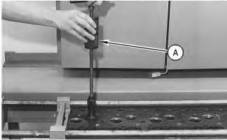
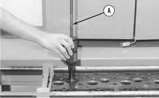
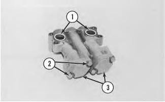
1. Remove the oil filter from engine oil filter base (1) with Tool (A).
2. Remove bolts (5), tube assembly (3) and the gasket. Remove the O-ring seal in tube assembly (3) and replace the O-ring seal, if necessary.
3. Remove the bolts that hold tube assembly (4) to the cylinder block. Remove tube assembly (4) and the gasket. Remove the O-ring seal in tube assembly (4) and replace the O-ring seal, if necessary.
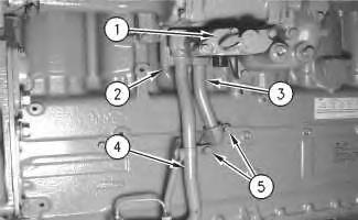
4. Remove four bolts (2) and engine oil filter base (1) from the cylinder block. Remove the Oring seals from engine oil filter base (1), if necessary. Copyright 1993 - 2019 Caterpillar Inc.
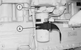 Illustration 1 g00499430
Illustration 2 g00499568
Illustration 1 g00499430
Illustration 2 g00499568
Previous Screen
Product: EXCAVATOR
Model: 235 EXCAVATOR 83X
Configuration: 235 EXCAVATOR 83X00444-UP (MACHINE) POWERED BY 3306 ENGINE
Disassembly and Assembly
3304B and 3306B Engines for Caterpillar Built Machines
Engine Oil Filter Base - Disassemble
SMCS - 1306-015
Disassembly Procedure
Start By:
A. Remove the engine oil filter and the engine oil filter base. Refer to Disassembly and Assembly, "Engine Oil Filter Base - Remove".
NOTICE
Keep all parts clean from contaminants.
Contaminants may cause rapid wear and shortened component life.
Suggest:
If the above button click is invalid.
Please download this document first, and then click the above link to download the complete manual.
Thank you so much for reading

Typical Example
Illustration 2
Typical Example
g00500559
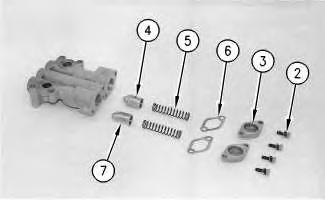
1. Remove O-ring seals (1) from the engine oil filter base. Remove four bolts (2), two covers (3) and two gaskets (6) .
Note: Plunger (4) is for the oil filter bypass. Plunger (7) is for the engine oil cooler bypass.
2. Remove springs (5), plunger (4) and plunger (7) from the engine oil filter base.