Installation Procedure
NOTICE
Keep all parts clean from contaminants. Contaminants may cause rapid wear and shortened component life.
Illustration 2
g00475568
1. Install the gasket and fuel shutoff solenoid (3) .
2. Apply 9S-3263 Thread Lock Compound on the threads for two nuts (2) .
3. Install the washers and two nuts (2) .
4. Connect ground wire (4) to the fuel shutoff solenoid. Install nut (1) and the washer. Copyright 1993 - 2019 Caterpillar Inc.

All
Private
Wed Oct 2 23:07:01 UTC+0800 2019
Rights Reserved.
Network For SIS Licensees.
Previous Screen
Product: EXCAVATOR
Model: 235 EXCAVATOR 81X
Configuration: 235 EXCAVATOR 81X00404-UP (MACHINE) POWERED BY 3306 ENGINE
Disassembly and Assembly
3304B and 3306B Engines for Caterpillar Built Machines Media
Automatic Timing Advance - Remove

SMCS - 1272-011
Removal Procedure Table 1
Required Tools
Start By:
A. Remove the front housing. Refer to Disassembly and Assembly, "Front Housing - Remove".
NOTICE
Keep all parts clean from contaminants.
Contaminants may cause rapid wear and shortened component life.
Shutdown SIS
Number -SENR5598-09 Publication Date -01/01/2013 Date Updated -25/01/2013 i00930839
Tool Part Number Part Description Qty A 5P-7307 Engine Turning Tool 1 B 0T-0065 Bolt 1 C 9S-9155 Spacer 1 8S-2264 Pump Impeller Puller 2 0T-0513 Bolt 2 5P-1075 Hard Washer 2
1. Follow the procedure in Steps 3 and 4 in order to time the fuel injection pump when the front cover is removed. Follow the procedure in Steps 6 and 7 in order to time the fuel injection pump when the front cover is installed.
Note: The No. 1 piston should be at the top center position on the compression stroke at the start of all timing procedures.
Note: The engine is seen from the flywheel end when the direction of the crankshaft rotation is given.

2. Remove the electric starting motor and install Tool (A) .
3. Turn the crankshaft counterclockwise until the "C" on the crankshaft gear and the "C" on the camshaft gear are in alignment.
 Illustration 1
g00474593
Illustration 2 g00474592
Illustration 1
g00474593
Illustration 2 g00474592
4. Remove two plugs and install Tool (B) in the flywheel housing. The large plug hole is for viewing.
5. To find the top center compression stroke for the No. 1 piston, use Tool (A) in order to turn the flywheel clockwise for approximately 30 degrees. This procedure should be used to remove all of the end play from the timing gears.
6. Use Tool (A) in order to turn the flywheel counterclockwise in the direction of the engine rotation until Tool (B) can be installed in the flywheel. The piston is at the top center position.

Note: If you go past the bolt hole, you must start the procedure again.
Note: Remove the breather assembly from the valve mechanism cover. The piston is at the top center position on the compression stroke when the inlet valve is closed and the exhaust valve is closed for the No. 1 cylinder. You must be able to move the rocker arms up and down with your hand.
7. Remove bolt (1) and washer (2) that secures the automatic timing advance.
 Illustration 3
g00474594
Illustration 4
g00474595
Illustration 3
g00474594
Illustration 4
g00474595
NOTICE
The automatic timing advance must have support during removal in order to help prevent damage to components.
8. Install bolt (1) and leave a 6.35 mm (.250 inch) gap. Install Tool (C), as shown. Tighten the stud in order to loosen the fuel pump drive gear from the taper on the fuel injection pump camshaft.
9. Remove Tool (C) and bolt (1). Remove the automatic timing advance.

Wed
23:07:57
Illustration 5 g00474596
Oct 2
Copyright 1993 - 2019 Caterpillar Inc. All Rights Reserved. Private Network For SIS Licensees. UTC+0800 2019
Shutdown SIS
Previous Screen
Product: EXCAVATOR
Model: 235 EXCAVATOR 81X
Configuration: 235 EXCAVATOR 81X00404-UP (MACHINE) POWERED BY 3306 ENGINE
Disassembly and Assembly
3304B and 3306B Engines for Caterpillar Built Machines
Automatic Timing Advance - Disassemble
SMCS - 1272-015
Disassembly Procedure

Start By:
A. Remove the automatic timing advance unit. Refer to Disassembly and Assembly, "Automatic Timing Advance - Remove".
NOTICE
Keep all parts clean from contaminants.
Contaminants may cause rapid wear and shortened component life.
Media Number -SENR5598-09 Publication Date -01/01/2013 Date Updated -25/01/2013 i00935438
1
Illustration
g00476292
1. Remove two screws (1) and plate (2) .
NOTICE
The weights are held in position with two springs for each weight that is under compression. Carefully remove the weights and the springs in order to help prevent possible injury.
Illustration 2
g00476293
2. Remove springs (3) and (5), weight (6) and slide (4) from each side of the assembly.

3.

Illustration 3 g00476294
If necessary, remove gear (7). Remove seals (8) and (9) . Copyright 1993 - 2019 Caterpillar Inc. All Rights Reserved. Private Network For SIS Licensees. Wed Oct 2 23:08:52 UTC+0800 2019
Previous Screen
Product: EXCAVATOR
Model: 235 EXCAVATOR 81X
Configuration: 235 EXCAVATOR 81X00404-UP (MACHINE) POWERED BY 3306 ENGINE
Disassembly and Assembly
3304B and 3306B Engines for Caterpillar Built Machines
Automatic Timing Advance - Assemble
SMCS - 1272-016
Assembly Procedure
NOTICE
Keep all parts clean from contaminants.
Contaminants may cause rapid wear and shortened component life.
Shutdown SIS
Media Number -SENR5598-09 Publication Date -01/01/2013 Date Updated -25/01/2013 i00935599
Illustration 1 g00476382
1. If dowels (3) were removed from the gear hub, installation dimension (X) is 9.00 ± 0.50 mm (.354 ± .020 inch).

2. Install seals (4) and (5) .
3. Put gear (1) in position on hub assembly (2) .

g00476383
4. Install slide (7), weight (9) and springs (6) and (8) on each side of the assembly.
Illustration 2
Illustration 3
5. Install plate (11) with two screws (10) .

g00476385
End By: Install the automatic timing advance unit. Refer to Disassembly and Assembly, "Automatic Timing Advance - Install".
Copyright 1993 - 2019 Caterpillar Inc. All Rights Reserved. Private Network For SIS Licensees.
Wed Oct 2 23:09:48 UTC+0800 2019
Previous Screen
Product: EXCAVATOR
Model: 235 EXCAVATOR 81X
Configuration: 235 EXCAVATOR 81X00404-UP (MACHINE) POWERED BY 3306 ENGINE
Disassembly and Assembly
3304B and 3306B Engines for Caterpillar Built Machines
Automatic Timing Advance - Install
SMCS - 1272-012
Installation Procedure Table 1
Required Tools
NOTICE
Keep all parts clean from contaminants.
Contaminants may cause rapid wear and shortened component life.
Shutdown SIS
Number -SENR5598-09 Publication Date -01/01/2013 Date Updated -25/01/2013 i00935398
Media
Tool Part Number Part Description Qty A 6V-4186 Fuel Pump Timing Pin 1 B 0L-2070 Bolt 1 C 5P-7307 Engine Turning Tool 1 D 4C-9874 Spanner Wrench 1
g00476281
1. Install washer (1) and bolt (2). Ensure that the cover of the fuel pump housing is removed. Turn the fuel pump camshaft in the direction of the engine rotation until Tool (A) can be installed in the notch of the camshaft.
2. Install Tool (A) and (B) into position. Install the weight assembly for the timing advance on the fuel injection pump camshaft.
g00476286
3. Use Tool (D) on the automatic timing advance and maintain a constant torque of 68 N·m (50 lb ft). Tighten the bolt that fastens the automatic timing advance to the fuel pump camshaft to a torque of 270 ± 25 N·m (200 ± 18 lb ft).

4. Remove Tools (A), (B), (C) and (D). Install the starting motor.
End By: Install the front housing. Refer to Disassembly and Assembly, "Front Housing - Install". Copyright 1993 - 2019
 Illustration 1
Illustration 2
Illustration 1
Illustration 2
All Rights Reserved. Private Network For SIS Licensees. Wed Oct 2 23:10:44 UTC+0800 2019
Caterpillar Inc.
Previous Screen
Product: EXCAVATOR
Model: 235 EXCAVATOR 81X
Configuration: 235 EXCAVATOR 81X00404-UP (MACHINE) POWERED BY 3306 ENGINE
Disassembly and Assembly
3304B and 3306B Engines for Caterpillar Built Machines
Shutdown SIS
Fuel Injection Pump Housing and Governor - Remove
SMCS - 1286-011
Removal Procedure Table 1
Required Tools
Start By:
a. Remove the fuel injection lines. Refer to Disassembly and Assembly, "Fuel Injection Lines - Remove and Install".
NOTICE
Keep all parts clean from contaminants.
Contaminants may cause rapid wear and shortened component life.
Number -SENR5598-09 Publication Date -01/01/2013 Date Updated -25/01/2013 i07103919
Media
Tool Part Number Part Description Qty A 8S-2264 Pump Impeller Puller 1 8B-7560 Step Plate 1 0T-0513 Bolt 2 5P-1075 Hard Washer 2
1. On the 3304B engine, remove oil supply line (26), oil drain line (25), and heat shield (27). Inspect the O-ring seal around oil drain line (25). Replace the O-ring seal if the O-ring seal is damaged. Remove the gaskets and the screen from the top of the turbocharger.


Note: The following illustrations are of a 3306B engine.
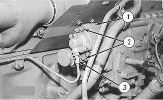
2. Remove six nuts (1) and the washers and remove cover (2).
Note: Separate nut (1) and the mounting stud, if the nut and the mounting stud come out of the housing together. Apply thread sealant to the mounting studs and reinstall the mounting studs to a depth of 19.0 ± 0.8 mm (0.74 ± 0.03 inch).
Illustration 1
g00589938
3304B Engine
Illustration 2
g00452289
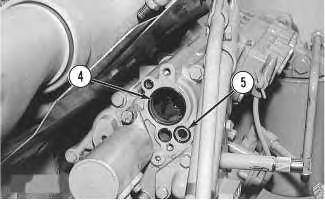
3. Remove center bolt (3) and spacer (4).
4. Install center bolt (3) and leave a gap of 6.4 mm (.25 inch). Install Tool (A), as shown. Tighten the stud to loosen the fuel pump drive gear from the taper on the fuel injection pump camshaft.


5. Remove Tool (A) and bolt (3).
 Illustration 3
g00452292
Illustration 4
g00452293
Illustration 5
g00452301
Illustration 3
g00452292
Illustration 4
g00452293
Illustration 5
g00452301
Suggest:
If the above button click is invalid.
Please download this document first, and then click the above link to download the complete manual.
Thank you so much for reading

6. Remove tube assemblies (5) and (11). Disconnect one end of tube assemblies (8) and (9). Disconnect clamp (10). Remove two bolts (7) and the washers and remove filter base (6) with the filter and the gasket.
7. Remove two bolts (12), the washers and the gasket. Remove two bolts (14) and the gasket. Remove tube assembly (13).
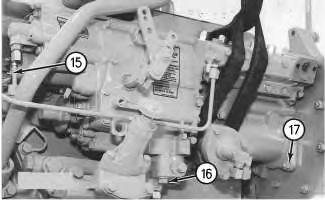
8. Use a lifting sling and a hoist to secure the fuel injection pump housing and the governor.
Note: Remove the heat shield (not shown) if equipped.
9. Disconnect solenoid ground (15). Remove three nuts (17). Remove two bolts (16) and the washers. Remove the fuel injection pump housing and the governor from the engine. To safely remove the fuel injection pump housing and the governor, use two technicians or a suitable lifting device. The weight of the 3304B fuel injection pump housing and governor is 24 kg (53 lb). The weight of the 3306B fuel injection pump housing and governor is 32 Kg (70 lb).
10. Remove the O-ring seals from the fuel injection pump housing and the governor.
Copyright 1993 - 2019 Caterpillar Inc.
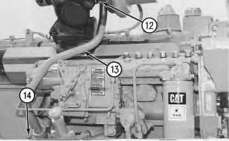 Illustration 6
g00452302
Illustration 7
g00452343
Illustration 6
g00452302
Illustration 7
g00452343
All
Private
For SIS Licensees. Wed Oct 2 23:11:40 UTC+0800 2019
Rights Reserved.
Network