
Service Repair Manual Model 235 EXCAVATOR
Shutdown SIS
Previous Screen
Product: EXCAVATOR
Model: 235 EXCAVATOR 64R
Configuration: 235 EXCAVATOR 64R01258-UP (MACHINE) POWERED BY 3306 ENGINE
Disassembly and Assembly
3304B and 3306B Engines for Caterpillar Built Machines
Pistons and Connecting Rods - Disassemble
SMCS - 1225-015
Disassembly Procedure
Table 1
Required Tools
Start By:
A. Remove the pistons and connecting rods. Refer to Disassembly and Assembly, "Pistons and Connecting Rods - Remove".
Keep all parts clean from contaminants.
Contaminants may cause rapid wear and shortened component life.
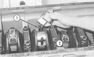
2. Remove retaining ring (3), piston pin (1) and connecting rod (2) .
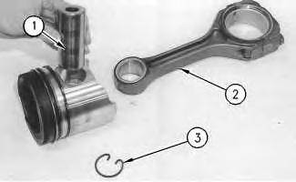
3. Remove the connecting rod bearing.
4. Heat the connecting rod in an oven to a temperature of 176 to 260 °C (350 to 500 °F). Do not use a direct flame to heat a connecting rod.
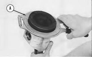
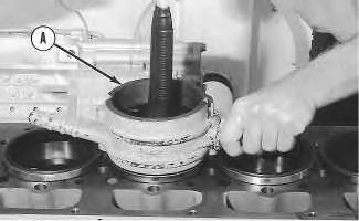
Illustration 1 g00484932 1. Remove the piston rings from the pistons with Tool (A) . Illustration 2 g00484980Hot oil and hot components can cause personal injury. Do not allow hot oil or hot components to contact the skin.
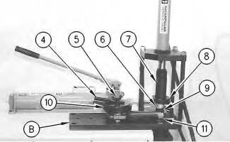
5. Put 6V-3029 Spacer (11) into the base plate. Put the connecting rod on the base plate of Tool (B) .
6. Put the connecting rod piston pin bearing end in the center of the port assembly of Tool (B). Install pin (5) in the center of the bore for the connecting rod bearing.
7. Install 6V-2049 Adapter (9). Align the hole in the adapter with the hole in the base plate of Tool (B) .
8. Install clamp bar (10) and clamp pin (4) .
Note: The old piston pin bearing is removed while the new piston pin bearing is installed.
9. Put the new piston pin bearing on the connecting rod. Install 5P-8645 Adapter (8) with the tapered end of the adapter toward the piston pin bearing. The piston pin bearing joint must be in alignment with the hole in 6V-2049 Adapter (9) and the base plate of Tool (B) .
10. Install adapter (7) from the press group on adapter (11) .
11. Use Tool (B) to push the new piston pin bearing (6) into the connecting rod. Press piston pin bearing (6) into position until adapter (8) makes contact with the connecting rod surface.
12. Remove the connecting rod and the old piston pin bearing from Tool (B) .
13. Check the piston pin bearing bore diameter after the bearing is installed. The correct inside diameter is 43.210 ± 0.008 mm (1.7012 ± 0.0003 inch). The clearance between the bearing and the piston pin must not be more than 0.08 mm (0.003 inch). Refer to Special Instruction, SMHS7295 for additional information on removing the piston pin bearings.
Previous Screen
Product: EXCAVATOR
Model: 235 EXCAVATOR 64R
Configuration: 235 EXCAVATOR 64R01258-UP (MACHINE) POWERED BY 3306 ENGINE
Disassembly and Assembly
3304B and 3306B Engines for Caterpillar Built Machines Media
Pistons and Connecting Rods - Assemble
SMCS - 1225-016
Assembly Procedure
Table 1
Required Tools
Tool Part Number Part Description
A 7S-9470 Piston Ring Expander 1
NOTICE
Keep all parts clean from contaminants.
Contaminants may cause rapid wear and shortened component life.
Shutdown SIS
1. Clean the grooves of the used pistons with an acceptable tool or 1U-8811 Cleaner .
2. Install the connecting rod bearings. Ensure that the tabs on the back side of the connecting rod bearings are in the tab grooves of the connecting rod and the connecting rod cap.
Illustration 1
g00486509
3. Install connecting rod (2) into the piston. Ensure that bearing tab slot (3) and the identification marks are on the same side as the "V" mark on the top of the piston.
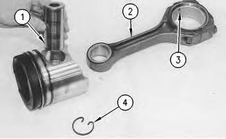
4. Lubricate piston pin (1) with clean engine oil and install piston pin (1) through the piston and connecting rod. Install retaining ring (4) on the end of the piston pin.
Illustration 2
g00484932
5. Install the oil control ring on the piston with Tool (A) .
Note: The spring ends of the oil control ring should be assembled 180 degrees from the ring end gap. The blue colored portion of the spring must be visible at the ring end gap.
6. Use Tool (A) to install the intermediate piston ring with the side marked "UP-2" toward the top of the piston.
7. Use Tool (A) to install the top piston ring with the side marked "UP-1" toward the top of the piston.
Note: The gaps in the intermediate piston ring and the top piston ring should be separated by 120 degrees.
End By: Install the pistons and connecting rods. Refer to Disassembly and Assembly, "Pistons and Connecting Rods - Install".
Previous Screen
Product: EXCAVATOR
Model: 235 EXCAVATOR 64R
Configuration: 235 EXCAVATOR 64R01258-UP (MACHINE) POWERED BY 3306 ENGINE
Disassembly and Assembly
3304B and 3306B Engines for Caterpillar Built Machines Media
Pistons and Connecting Rods - Install
SMCS - 1225-012
Installation Procedure
Table 1
Required Tools
Tool Part Number Part Description
A 5P-3525 Piston Ring Compressor 1
NOTICE
Keep all parts clean from contaminants.
Contaminants may cause rapid wear and shortened component life.
Shutdown SIS
1. Rotate the crankshaft until the bearing journals are at the bottom center. The bearing journals that are at the bottom center are for the piston installation.
2. Put clean engine oil on the crankshaft journals and on the inside of the cylinder liners. Put clean engine oil on the piston rings and the connecting rod bearings.
3. Move the piston rings on the pistons until the ring openings are separated by approximately 120 degrees.
4. Put the piston in the cylinder liner with the "V" mark on the piston in alignment with the "V" mark on the cylinder block. Put tool (A) in position on the cylinder block and compress the piston rings.
NOTICE
The "V" mark must be visible on the piston and the cylinder block. If the "V" mark is not visible, the piston must be installed with the relief for the valve positioned toward the pushrod opening in the cylinder block. Damage may result if the pistons are not installed properly.
5. Push the piston into the cylinder liner and out of the ring compressor.
6. Guide connecting rod (1) into position on the crankshaft.
7. Put clean engine oil (SAE 30) on the lower half of the connecting rod bearing and on the connecting rod bolts.
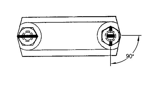
Illustration 1 g00483337 Illustration 2 g00483701NOTICE
When the connecting rod caps are installed, ensure that the identification marks are aligned.
8. Install connecting rod cap (2) and the nuts that secure the connecting rod cap. Torque both of the nuts to 40 ± 4 N·m (30 ± 3 lb ft). Mark the position of the nuts. Tighten each nut for an additional 90 degrees (1/4 turn).
9. Repeat Steps 1 through 8 for the remainder of the piston and connecting rods.
End By:
a. Install the engine oil pump. Refer to Disassembly and Assembly, "Engine Oil PumpInstall".
b. Install the engine oil pan plate. Refer to Disassembly and Assembly, "Engine Oil Pan PlateRemove and Install".
c. Install the spacer plate. Refer to Disassembly and Assembly, "Spacer Plate - Remove and install".
Copyright 1993 - 2019 Caterpillar Inc.
Previous Screen
Product: EXCAVATOR
Model: 235 EXCAVATOR 64R
Configuration: 235 EXCAVATOR 64R01258-UP (MACHINE) POWERED BY 3306 ENGINE
Disassembly and Assembly
3304B and 3306B Engines for Caterpillar Built Machines
Connecting Rod Bearings - Remove
SMCS - 1219-011
Removal Procedure
Start By:
A. Remove the engine oil pump. Refer to Disassembly and Assembly, "Engine Oil PumpRemove".
B. Remove the oil pan plate. Refer to Disassembly and Assembly, "Engine Oil Pan PlateRemove and Install".
NOTICE
Keep all parts clean from contaminants.
Contaminants may cause rapid wear and shortened component life.
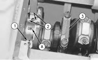
Illustration 1
g00487412
1. Turn the crankshaft until two of the pistons are at the bottom center. Remove connecting rod nuts (1) from the connecting rod. Remove connecting rod cap (2) for each connecting rod.
Note: The connecting rod bolts can fall out of the connecting rods when the connecting rod nuts are removed.
2. Remove the lower half of the connecting rod bearing from connecting rod cap (2) .
3. Carefully push the connecting rod into the cylinder liner for bearing removal. Remove the upper half of the connecting rod bearing from the connecting rod.
4. Repeat Steps 1 through 3 for the remaining connecting rod bearings. Copyright 1993 - 2019 Caterpillar Inc. All Rights Reserved. Private Network For SIS Licensees.
Previous Screen
Product: EXCAVATOR
Model: 235 EXCAVATOR 64R
Configuration: 235 EXCAVATOR 64R01258-UP (MACHINE) POWERED BY 3306 ENGINE
Disassembly and Assembly
3304B and 3306B Engines for Caterpillar Built Machines
Connecting Rod Bearings - Install
SMCS - 1219-012
Installation Procedure
Table 1
Tool Part Number Part Description Qty A - Plastigage -
NOTICE
Keep all parts clean from contaminants.
Contaminants may cause rapid wear and shortened component life.
Shutdown SIS
Note: Install the connecting rod bearings dry when the clearance checks are made. Put clean engine oil on the connecting rod bearings for final assembly.
1. Install the upper half of the connecting rod bearing in the connecting rod.
2. Install the lower half of the connecting rod bearing in the connecting rod.
Note: Align the tabs on the back of the connecting rod bearings with the tab grooves in the connecting rod.
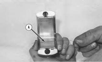
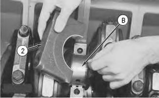
3. In order to check the connecting rod bearing clearance, put Tool (A) on the connecting rod bearing, as shown.
4. Put clean engine oil (SAE 30) on the connecting rod bolts.
NOTICE
When the connecting rod caps are installed, ensure that the identification marks are aligned.
Note: Do not turn the crankshaft when Tool (A) is positioned.
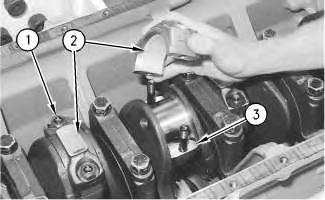
5. Ensure that connecting rod (3) is in position on the crankshaft. Install connecting rod cap (2) and connecting rod nuts (1) on connecting rod (3) .
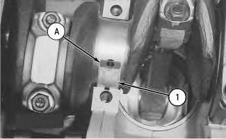
Illustration 1
g00487493
Illustration 2
g00487412
6. Tighten the connecting rod nuts to a torque of 40 ± 4 N·m (30 ± 3 lb ft). Mark the position of the nuts. Tighten each nut for an additional 90 degrees (1/4 turn).
7. Remove the connecting rod cap. Measure Tool (A) on the bearing surface before Tool (A) is removed. The clearance between the connecting rod bearing and a new crankshaft should be 0.076 to 0.168 mm (.0025 to .0066 inch). The clearance between the connecting rod bearing and a used crankshaft should be 0.25 mm (0.01 inch).
8. Install connecting rod cap (2) and connecting rod nuts (1) on connecting rod (3). Repeat Step 6 in order to tighten the nuts.
9. Repeat Steps 1 through 8 for the remaining connecting rod bearings.
End By:
a. Install the oil pan plate. Refer to Disassembly and Assembly, "Engine Oil Pan PlateRemove and Install".
b. Install the engine oil pump. Refer to Disassembly and Assembly, "Engine Oil PumpInstall".
Copyright 1993 - 2019 Caterpillar Inc. All Rights Reserved. Private Network For SIS Licensees.
Previous Screen
Product: EXCAVATOR
Model: 235 EXCAVATOR 64R
Configuration: 235 EXCAVATOR 64R01258-UP (MACHINE) POWERED BY 3306 ENGINE
Disassembly and Assembly
3304B and 3306B Engines for Caterpillar Built Machines Media
Crankshaft Main Bearings - Remove
SMCS - 1203-011
Removal Procedure Table 1
Required Tools
Start By:
A. Remove the engine oil pump. Refer to Disassembly and Assembly, "Engine Oil PumpRemove".
B. Remove the oil pan plate. Refer to Disassembly and Assembly, "Engine Oil Pan PlateRemove and Install".
NOTICE
Keep all parts clean from contaminants.
Contaminants may cause rapid wear and shortened component life.
1. Remove No. 1, 3, 5 and 7 main bearing caps (3). Remove the lower halves of the main bearings from the main bearing caps.
Note: If the crankshaft is turned in the wrong direction, the tab on the bearing will be pushed between the crankshaft and the bearing area in the cylinder block. This can result in damage to the cylinder block and/or the crankshaft.
2. Install Tool (A) in the oil hole in the crankshaft journal. Turn the crankshaft in order to remove the upper halves of main bearings (1) .
3. Remove crankshaft thrust plates (2) from the crankshaft.
4. Install No. 1, 3, 5, and 7 main bearing caps (3). Refer to Disassembly and Assembly, "Crankshaft Main Bearings - Install".
5. Remove the remaining main bearing caps (No. 2, 4 and 6) (3). Remove the lower halves of the main bearings from the main bearing caps.
Note: If the crankshaft is turned in the wrong direction, the tab on the bearing will be pushed between the crankshaft and the bearing area in the cylinder block. This can result in damage to the cylinder block and/or the crankshaft.
6. Install Tool (A) in the hole in the crankshaft journal. Turn the crankshaft in order to remove the upper halves of main bearings (1) .
Previous Screen
Product: EXCAVATOR
Model: 235 EXCAVATOR 64R
Configuration: 235 EXCAVATOR 64R01258-UP (MACHINE) POWERED BY 3306 ENGINE
Disassembly and Assembly
3304B and 3306B Engines for Caterpillar Built Machines Media
Crankshaft Main Bearings - Install
SMCS - 1203-012
Installation Procedure Table 1
Required Tools
Tool
A
B - Plastigage -
C 8T-5096 Dial Indicator Group 1
NOTICE
Keep all parts clean from contaminants.
Contaminants may cause rapid wear and shortened component life.
Shutdown SIS
Note: Install the main bearings dry when the clearance checks are made. Put clean engine oil on the main bearings for final assembly.
Note: Ensure that the upper halves and the lower halves of the main bearings are installed so that the bearing tabs fit into the notch in the cylinder block and in the main bearing caps.
1. Use Tooling (A) and install the new upper halves of main bearings (1) in the cylinder block. Install new lower halves of main bearings (1) in main bearing caps (2) .
Note: When the bearing clearance is checked and the engine is in an upright position or on the engine's side, the crankshaft must be supported against the upper halves of the main bearings. This is done in order to get a correct measurement with Tooling (B) . If the crankshaft is not supported, the weight of the crankshaft will cause an incorrect reading. If the engine is not in an upright position or on the engine's side, it is not necessary to support the crankshaft. Do not rotate the crankshaft when Tooling (B) is positioned.
Note: Refer to Guideline For Reusable Parts, SEBV0544, "Engine Bearings and Crankshafts" for complete details concerning the measurement of bearing clearances.
2. Check the main bearing clearance with Tooling (B) , as follows:
a. Put a piece of Tooling (B) on the crankshaft journals, as shown.
Note: Make sure that the part number on the main bearing cap is facing toward the front of the engine. Also, make sure that the number on the main bearing cap matches the number on the cylinder block on the left side of each main bearing cap.
Illustration 1 g00479169 Illustration 2 g00479171b. Put main bearing caps (2) in position in the engine. Put 4C-5593 Anti-Seize Compound on the bolt threads and the face of the washers. Install the bolts and tighten the bolts to torque of 40 ± 4 N·m (30 ± 3 lb ft).
c. Put a mark on each bolt and main bearing cap. Tighten the bolts for an additional 90 degrees (1/4 turn).
d. Remove the main bearing caps and measure Tooling (B) in order to find the bearing clearance. The main bearing clearance for new bearings must be 0.076 to 0.165 mm (0.0030 to 0.0065 inch). The maximum permissible clearance with used bearings is 0.25 mm (0.010 inch).
Illustration 3
g00479203
3. Put clean oil on thrust plate (4) and install a new thrust plate for the rear main bearing. Install the new thrust plate so that the mark that is identified as the "BLOCK SIDE" faces toward the cylinder block and toward the tabs on the thrust plates in the machined area on the cylinder block. Tabs (3) on thrust plate (4) will not allow the thrust plate to be installed backward.
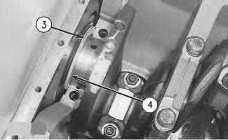
Illustration 4
g00479205
4. Install main bearing caps (2) . Use the same procedure that is described in Step 2.b and Step 2.c.
5. Remove the remainder of the main bearing caps. Perform Steps 1, 2 and 4 again.
6. Use Tooling (C) in order to check the crankshaft end play. The end play is controlled by the thrust plates on the rear main bearing. End play with new bearings must be 0.122 to 0.579 mm (0.0048 to 0.0228 inch).
End By:
a. Install the oil pan plate. Refer to Disassembly and Assembly, "Engine Oil Pan Plateremove and install".
b. Install the engine oil pump. Refer to Disassembly and Assembly, "Engine Oil PumpInstall".
Copyright 1993 - 2019 Caterpillar Inc.
Previous Screen
Product: EXCAVATOR
Model: 235 EXCAVATOR 64R
Configuration: 235 EXCAVATOR 64R01258-UP (MACHINE) POWERED BY 3306 ENGINE
Disassembly and Assembly
3304B and 3306B Engines for Caterpillar Built Machines
Crankshaft - Remove
SMCS - 1202-011
Removal Procedure Table 1
Required Tools
Start By:
A. Remove the front housing. Refer to Disassembly and Assembly, "Front Housing - Remove".
B. Remove the flywheel housing. Refer to Disassembly and Assembly, "Flywheel HousingRemove and Install".
C. Remove the engine oil pump. Refer to Disassembly and Assembly, "Engine Oil PumpRemove".
D. Remove the oil pan plate. Refer to Disassembly and Assembly, "Engine Oil Pan PlateRemove and Install".
Keep all parts clean from contaminants.
Contaminants may cause rapid wear and shortened component life.
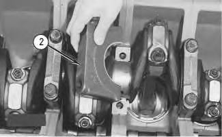
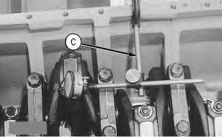
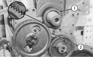
1. Turn the crankshaft until timing mark "C" on crankshaft gear (1) is aligned with timing mark "C" on camshaft gear (2) .
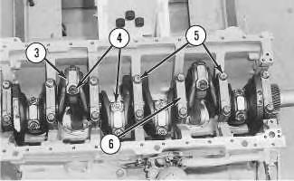
2. Remove connecting rod nuts (4) and connecting rod caps (3) from the connecting rods.
Suggest:
If the above button click is invalid.
Please download this document first, and then click the above link to download the complete manual.
Thank you so much for reading

Damage may occur to the fuel injection nozzle or the piston if the piston and connecting rod are pushed too far down in the cylinder liners.
Note: The piston will be difficult to push down into the cylinder when the inlet valves and exhaust valves are closed.
3. Push down on the pistons that are not at the top center position in order to clear the crankshaft.
4. Remove main bearing cap bolts (5) and main bearing caps (6) from the cylinder block.
5. Remove thrust plates (7) from the rear main bearing.
6. Install Tool (A) and a suitable lifting device on crankshaft (8), as shown. Lift the crankshaft straight up from the cylinder block. The weight of the 3304B crankshaft is 65 kg (143 lb). The weight of the 3306B crankshaft is 95 Kg (210 lb).
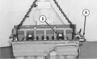
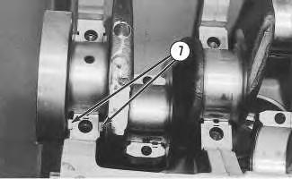 Illustration 3
g00503320
Illustration 4
g00503353
Illustration 3
g00503320
Illustration 4
g00503353