Shutdown SIS
Previous Screen
Product: SKID STEER LOADER
Model: 226 SKID STEER LOADER 5FZ
Configuration: 216 226 232 242 Skid Steer Loader 5FZ06700-UP (MACHINE) POWERED BY 3024C, 3034 Engine
Disassembly and Assembly
216, 226, 232 and 242
Skid Steer Loaders Machine Systems
Tilt Cylinder - Remove
SMCS - 5104-011
S/N - 4NZ3400-UP
S/N - 5FZ6700-UP
Removal Procedure
Table 1
REQUIRED TOOLS
A 1U-9759 Jack Stand 2
B 1U-9760 Jack Stand 2
Start By:
A. Release the hydraulic system pressure. Refer to Disassembly and Assembly, "Hydraulic System Pressure - Release".
B. Remove the quick coupler. Refer to Disassembly and Assembly, "Quick Coupler - Remove and Install".
Personal injury can result from hydraulic oil pressure and hot oil.
Hydraulic oil pressure can remain in the hydraulic system after the engine has been stopped. Serious injury can be caused if this pressure is not released before any service is done on the hydraulic system.
Make sure all of the attachments have been lowered, oil is cool before removing any components or lines. Remove the oil filler cap only when the engine is stopped, and the filler cap is cool enough to touch with your bare hand.
NOTICE
Care must be taken to ensure that fluids are contained during performance of inspection, maintenance, testing, adjusting and repair of the product. Be prepared to collect the fluid with suitable containers before opening any compartment or disassembling any component containing fluids.
Refer to Special Publication, NENG2500, "Caterpillar Tools and Shop Products Guide" for tools and supplies suitable to collect and contain fluids on Caterpillar products.
Dispose of all fluids according to local regulations and mandates.
Note: Put identification marks on all lines and on all cylinders for installation purposes. Plug all lines. This will help to prevent fluid loss and this helps to keep contaminants from entering the system.
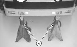 Illustration 1
g00593382
1. Use Tooling (A) to support the rear of the machine.
Illustration 1
g00593382
1. Use Tooling (A) to support the rear of the machine.
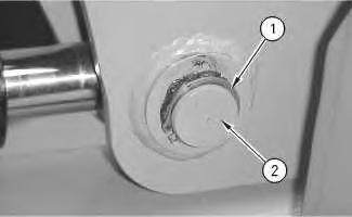
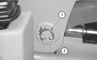
2. Remove snap ring (1) from the front of each lift cylinder.
3. Remove pin (2) from the front of each lift cylinder.
4. Attach a suitable lifting device in order to raise the lift arm assembly.
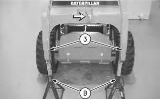 Illustration 2
5. Use Tooling (B) in order to support lift arm assembly (3) .
6
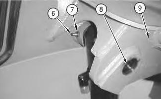
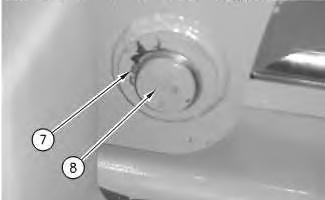
7. Remove nut (7) and bolt (6) .
8. Remove pin (8) from the tilt cylinder.
9. Remove the tilt cylinder from the lift arm assembly (9) .
10. Repeat Steps 7 through 9 for the opposite side.
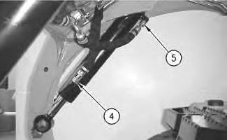
Illustration 5 g00684660 6. Disconnect lines (4) and (5) from each tilt cylinder. Illustration g00684669Shutdown SIS
Previous Screen
Product: SKID STEER LOADER
Model: 226 SKID STEER LOADER 5FZ
Configuration: 216 226 232 242 Skid Steer Loader 5FZ06700-UP (MACHINE) POWERED BY 3024C, 3034 Engine
Disassembly and Assembly
216, 226, 232 and 242
Skid Steer Loaders Machine Systems
Tilt Cylinder - Install
SMCS - 5104-012
S/N - 4NZ3400-UP
S/N - 5FZ6700-UP
Installation Procedure
REQUIRED TOOLS
Personal injury can result from hydraulic oil pressure and hot oil.
Hydraulic oil pressure can remain in the hydraulic system after the engine has been stopped. Serious injury can be caused if this pressure is not released before any service is done on the hydraulic system.
Make sure all of the attachments have been lowered, oil is cool before removing any components or lines. Remove the oil filler cap only when the engine is stopped, and the filler cap is cool enough to touch with your bare hand.
NOTICE
Care must be taken to ensure that fluids are contained during performance of inspection, maintenance, testing, adjusting and repair of the product. Be prepared to collect the fluid with suitable containers before opening any compartment or disassembling any component containing fluids.
Refer to Special Publication, NENG2500, "Caterpillar Tools and Shop Products Guide" for tools and supplies suitable to collect and contain fluids on Caterpillar products.
Dispose of all fluids according to local regulations and mandates.
Illustration 1
g00684669
1. Position the tilt cylinder into lift arm assembly (9) .
2. Install pin (8) into the tilt cylinder.
3. Install bolt (6) and nut (7). Tighten the bolt to a torque of 28 ± 7 N·m (21 ± 5 lb ft).
4. Repeat Steps 1 through 3 for the opposite side.
Illustration 2
5. Connect lines (4) and (5) to each tilt cylinder.
Illustration 3
6. Use a suitable lifting device to lift the lift arm assembly upward.
7. Remove Tooling (B) from the lift arm assembly (3) .
8. Use a suitable lifting device to lower the lift arm assembly.
g00684660
g00684652
Illustration 4
g00593394
9. Install pin (2) into each of the lift cylinder.
10. Install snap ring (1) onto the pin of each lift cylinder.
Illustration 5
g00593382
11. Remove Tooling (A) from the rear of the machine.
12. Check the hydraulic oil level. Refer to Operation and Maintenance Manual, SEBU7468, "Hydraulic System Oil Level - Check".
End By: Install the quick coupler. Refer to Disassembly and Assembly, "Quick Coupler - Remove and Install".
Copyright 1993 - 2019 Caterpillar Inc. All Rights Reserved. Private Network For SIS Licensees.
Shutdown SIS
Previous Screen
Product: SKID STEER LOADER
Model: 226 SKID STEER LOADER 5FZ
Configuration: 216 226 232 242 Skid Steer Loader 5FZ06700-UP (MACHINE) POWERED BY 3024C, 3034 Engine
Disassembly and Assembly
216, 226, 232 and 242
Skid Steer Loaders Machine Systems
Lift Cylinder - Remove
SMCS - 5102-011
S/N - 4NZ3400-UP
S/N - 5FZ6700-UP
Removal Procedure
Start By:
A. Release the hydraulic system pressure. Refer to Disassembly and Assembly, "Hydraulic System Pressure - Release".
B. Tilt the cab. Refer to Disassembly and Assembly, "Cab -Tilt".
Personal injury can result from hydraulic oil pressure and hot oil.
Hydraulic oil pressure can remain in the hydraulic system after the engine has been stopped. Serious injury can be caused if this pressure is not released before any service is done on the hydraulic system.
Make sure all of the attachments have been lowered, oil is cool before removing any components or lines. Remove the oil filler cap only when the engine is stopped, and the filler cap is cool enough to touch with your bare hand.
Care must be taken to ensure that fluids are contained during performance of inspection, maintenance, testing, adjusting and repair of the product. Be prepared to collect the fluid with suitable containers before opening any compartment or disassembling any component containing fluids.
Refer to Special Publication, NENG2500, "Caterpillar Tools and Shop Products Guide" for tools and supplies suitable to collect and contain fluids on Caterpillar products.
Dispose of all fluids according to local regulations and mandates.
Note: Put identification marks on all lines and on all cylinders for installation purposes. Plug all lines. This will help to prevent fluid loss and this helps to keep contaminants from entering the system.
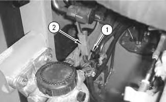
1. Disconnect lines (1) and (2) .
2. Remove retaining pin (3) and lower the loader lift arm brace onto the lift cylinder.
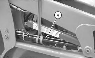
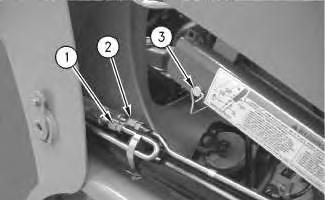 Illustration 1
g00792871
Illustration 1
g00792871
Illustration 2 g00792879
3. Attach a suitable lifting device to cylinder assembly (4) .
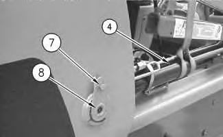
Illustration 3 g00591488
4. Remove snap ring (5) .
5. Remove pin (6) .
Illustration 4 g00795160
6. Remove bolt (7) and the washer.

7. Remove pin assembly (8) from the lift cylinder.
8. Remove lift cylinder assembly (4) and the loader lift arm brace. Weight of the lift cylinder and the loader lift arm brace is 32 kg (70 lb).
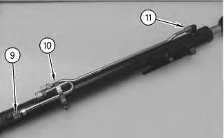
Illustration 5
9. Loosen clamp (10) and remove lines (9) and (11) .
10. Repeat Steps 1 through 9 for the opposite side.
Shutdown SIS
Previous Screen
Product: SKID STEER LOADER
Model: 226 SKID STEER LOADER 5FZ
Configuration: 216 226 232 242 Skid Steer Loader 5FZ06700-UP (MACHINE) POWERED BY 3024C, 3034 Engine
Disassembly and Assembly
216, 226, 232 and 242
Skid Steer Loaders Machine Systems
Lift Cylinder - Install
SMCS - 5102-012
S/N - 4NZ3400-UP
S/N - 5FZ6700-UP
Installation Procedure
Personal injury can result from hydraulic oil pressure and hot oil.
Hydraulic oil pressure can remain in the hydraulic system after the engine has been stopped. Serious injury can be caused if this pressure is not released before any service is done on the hydraulic system.
Make sure all of the attachments have been lowered, oil is cool before removing any components or lines. Remove the oil filler cap only when the engine is stopped, and the filler cap is cool enough to touch with your bare hand.
NOTICE
Care must be taken to ensure that fluids are contained during performance of inspection, maintenance, testing, adjusting and repair of the product. Be prepared to collect the fluid with suitable containers
before opening any compartment or disassembling any component containing fluids.
Refer to Special Publication, NENG2500, "Caterpillar Tools and Shop Products Guide" for tools and supplies suitable to collect and contain fluids on Caterpillar products.
Dispose of all fluids according to local regulations and mandates.
1. Install line (9) and line (11) .
2. Tighten clamp (10) .
3. Attach a suitable lifting device to lift cylinder assembly (4). The weight of the lift cylinder assembly is 32 kg (70 lb).
4. Position the lift cylinder assembly and the loader lift arm brace on the machine.
Illustration 1
g00690798
Illustration 2
g00795160
Illustration 4
7. Connect lines (1) and (2) .
8. Raise the loader lift arm brace and install retaining pin (3) .
9. Repeat steps 1 through 8 for the lift cylinder on the opposite side.
10. Check hydraulic oil level. Refer to Operation and Maintenance Manual, SEBU7468, "Hydraulic System Oil Level - Check".
Copyright 1993 - 2019 Caterpillar Inc.
5. Install pin assembly (8), the washer, and bolt (7) . Illustration 3 g00591488 6. Install pin (6) and snap ring (5) . g00792871Shutdown SIS
Previous Screen
Product: SKID STEER LOADER
Model: 226 SKID STEER LOADER 5FZ
Configuration: 216 226 232 242 Skid Steer Loader 5FZ06700-UP (MACHINE) POWERED BY 3024C, 3034 Engine
Disassembly and Assembly
216, 226, 232 and 242
Skid Steer Loaders Machine Systems
Lift Arms - Remove
SMCS - 6119-011
S/N - 4NZ3400-UP
S/N - 5FZ6700-UP
Removal Procedure
Start By:
A. Release the hydraulic system pressure. Refer to Disassembly and Assembly, "Hydraulic System Pressure - Release".
B. Remove the quick coupler. Refer to Disassembly and Assembly, "Quick Coupler - Remove and Install".
C. Remove the tilt cylinder. Refer to Disassembly and Assembly, "Tilt Cylinder - Remove".
D. Tilt the cab. Refer to Disassembly and Assembly, "Cab-Tilt".
Personal injury can result from hydraulic oil pressure and hot oil.
Hydraulic oil pressure can remain in the hydraulic system after the engine has been stopped. Serious injury can be caused if this pressure is not released before any service is done on the hydraulic system.
Make sure all of the attachments have been lowered, oil is cool before removing any components or lines. Remove the oil filler cap only when the engine is stopped, and the filler cap is cool enough to touch with your bare hand.
NOTICE
Care must be taken to ensure that fluids are contained during performance of inspection, maintenance, testing, adjusting and repair of the product. Be prepared to collect the fluid with suitable containers before opening any compartment or disassembling any component containing fluids.
Refer to Special Publication, NENG2500, "Caterpillar Tools and Shop Products Guide" for tools and supplies suitable to collect and contain fluids on Caterpillar products.
Dispose of all fluids according to local regulations and mandates.
Note: Put identification marks on all lines and on all wires for installation purposes. Plug all lines. This will help to prevent fluid loss and this helps to keep contaminants from entering the system.
 1. Open the engine access door.
Illustration 1
g00594375
2. Remove strap (1) and disconnect harness (2) .
1. Open the engine access door.
Illustration 1
g00594375
2. Remove strap (1) and disconnect harness (2) .
3. Remove two bolts (3) and washers from the bracket. Move bracket (4) with the harness aside.
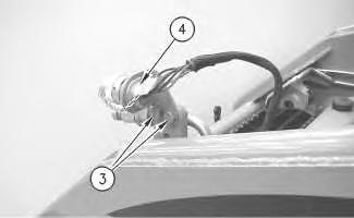
4. Disconnect lines (5) and (6) from the lift arm assembly.
5. Repeat step 4 on the opposite side.
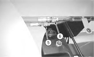 Illustration 2
g00589421
Illustration 3
g00593552
Illustration 2
g00589421
Illustration 3
g00593552
Illustration 4 g00790815
6. Remove snap ring (7) from the rod end of the cylinder.
7. Remove pin (8) .
8. Repeat steps 6 and 7 for the opposite side.
Illustration 5 g00790823
9. Remove two bolts (9) and two clips (10) from the lines under the lift arm assembly.
10. Repeat step 9 for the opposite side of the lift arm assembly.
Illustration 6
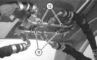
11. Remove two bolts (11), two clips (12), and the line assemblies from the underside of the lift arm assembly.
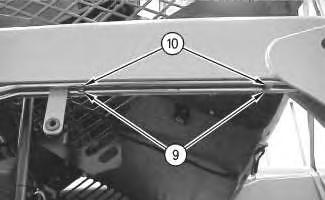 g00790828
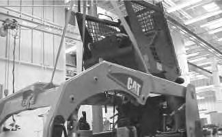
Illustration 7 g00593621
12. Use a suitable lifting device to support the lift arms.
Illustration 8
g00790831
13. Remove bolt (13) and pin assembly (14) from both sides of the lift arm assembly.
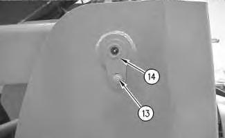
14. Remove the lift arm assembly from the machine. The weight of the lift arm assembly is 322 kg (710 lb).
Copyright 1993 - 2019 Caterpillar Inc. All Rights Reserved. Private Network For SIS Licensees.
Thu Oct 10 13:03:50 UTC+0800 2019
Shutdown SIS
Previous Screen
Product: SKID STEER LOADER
Model: 226 SKID STEER LOADER 5FZ
Configuration: 216 226 232 242 Skid Steer Loader 5FZ06700-UP (MACHINE) POWERED BY 3024C, 3034 Engine
Disassembly and Assembly
216, 226, 232 and 242
Skid Steer Loaders Machine Systems
Lift Arms - Install
SMCS - 6119-012
S/N - 4NZ3400-UP
S/N - 5FZ6700-UP
Installation Procedure
Personal injury can result from hydraulic oil pressure and hot oil.
Hydraulic oil pressure can remain in the hydraulic system after the engine has been stopped. Serious injury can be caused if this pressure is not released before any service is done on the hydraulic system.
Make sure all of the attachments have been lowered, oil is cool before removing any components or lines. Remove the oil filler cap only when the engine is stopped, and the filler cap is cool enough to touch with your bare hand.
NOTICE
Care must be taken to ensure that fluids are contained during performance of inspection, maintenance, testing, adjusting and repair of the product. Be prepared to collect the fluid with suitable containers
before opening any compartment or disassembling any component containing fluids.
Refer to Special Publication, NENG2500, "Caterpillar Tools and Shop Products Guide" for tools and supplies suitable to collect and contain fluids on Caterpillar products.
Dispose of all fluids according to local regulations and mandates.
1. Attach a suitable lifting device to the lift arm assembly in order to position the lift arm assembly to the machine. The weight of the lift arm assembly is 322 kg (710 lb).
2. Install pin assembly (14) and bolt (13) to both sides of the lift arm assembly.
Illustration 1 g00593621
Illustration 2 g00790831
Suggest:
If the above button click is invalid.
Please download this document first, and then click the above link to download the complete manual.
Thank you so much for reading
 Illustration 3
g00790828
3. Position the line assemblies on the underside of the lift arm assembly. Install two clips (12) and two bolts (11) .
Illustration 4
g00790823
4. Install two clips (10) and two bolts (9) on the lines under the lift arms.
5. Repeat step 4 for the opposite side of the lift arm assembly.
Illustration 3
g00790828
3. Position the line assemblies on the underside of the lift arm assembly. Install two clips (12) and two bolts (11) .
Illustration 4
g00790823
4. Install two clips (10) and two bolts (9) on the lines under the lift arms.
5. Repeat step 4 for the opposite side of the lift arm assembly.