Shutdown SIS
Previous Screen
Product: SKID STEER LOADER
Model: 216B3 SKID STEER LOADER JXM
Configuration: 216B3 Skid Steer Loader JXM00001-UP (MACHINE) POWERED BY C2.2 Engine
Disassembly and Assembly
259B3 Compact Track Loader, 247B3 and 257B3 Multi Terrain Loaders and 216B3, 226B3, 236B3, 242B3 and 252B3 Skid Steer Loaders Power Train
Piston Pump (Hydrostatic) - Disassemble
SMCS - 5070-015-H7
Disassembly Procedure
Table 1
Required Tools
Start By:
a. Remove the piston pump. Refer to Disassembly and Assembly, "Piston Pump - Remove".
Note: The following procedure is intended for cleaning purposes only.
Make sure to wear all necessary protective equipment.
Follow the recommended procedure and use all recommended tooling to release
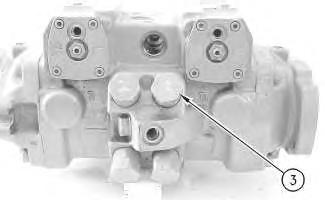
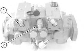 Illustration 1
g00903455
1. Remove the fittings and connectors (1).
2. Remove speed sensing valve (2).
Illustration 2
g00903457
Personal injury can result from being struck by parts propelled by a released spring force.
the spring force.
3. Remove cover (3) and the spring for the crossover relief valve.
Illustration 1
g00903455
1. Remove the fittings and connectors (1).
2. Remove speed sensing valve (2).
Illustration 2
g00903457
Personal injury can result from being struck by parts propelled by a released spring force.
the spring force.
3. Remove cover (3) and the spring for the crossover relief valve.
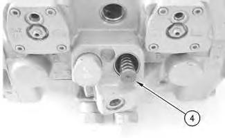
4. Remove seat (4).
5. Note the orientation of spring (5).
6. Remove O-ring seal (6) from cover (3).
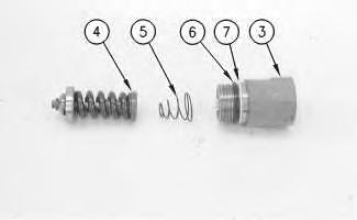
7. Remove back up ring (7) from cover (3).
8. Repeat Step 3 through Step 7 for the other covers.
Illustration 3 g00903461 Illustration 4 g00903467 Illustration 5 g0090350011.
12.
13.
Personal injury can result from being struck by parts propelled by a released spring force.
Make sure to wear all necessary protective equipment.
Follow the recommended procedure and use all recommended tooling to release the spring force.
g00903502
g00903503
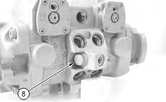
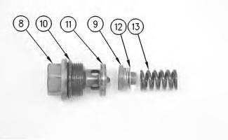
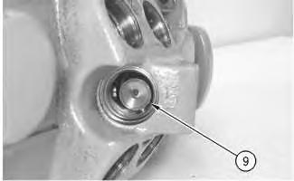
9. Remove plug (8) for the charge relief valve. Illustration 6 Illustration 7 10. Remove seat (9). Remove shims (12). Remove spring (13). Remove seal (11) from plug (8).14. Remove O-ring seal (10) from plug (8).
15. Use Tooling (A) to measure the distance from the stud to the nut. Record the distance for assembly purposes.
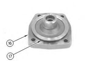
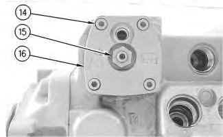
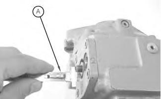
Illustration 9 g00904929
16. Remove screws (14).
17. Remove nut (15).
18. Remove cover (16).
Illustration 8 g01178122Illustration 10 g00904930
19. Remove O-ring seal (17) from cover (16).
Illustration 11
g00904933
20. Use Tooling (B) to remove retaining ring (18). Remove actuator assembly (19).
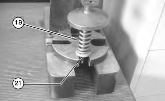
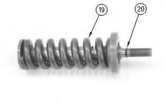
Illustration 12
g00905018
21. Remove O-ring seal (20) from actuator assembly (19).
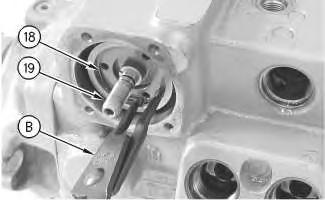
Illustration 13
g01054368
Personal injury can result from being struck by parts propelled by a released spring force.
Make sure to wear all necessary protective equipment.
Follow the recommended procedure and use all recommended tooling to release the spring force.
Illustration 14
g01054370
Note: Keepers (21) must be marked for assembly. Do not mix keepers (21). The keepers are not interchangeable.
22. Place actuator assembly (19) in a suitable press.
23. Remove keepers (21).
24. Remove shaft (26).
25. Remove spring retainer (22).
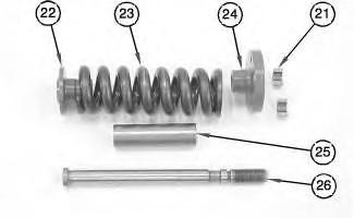
26. Remove spring (23).
27. Remove spring retainer (24).
28. Remove spacer (25).
29. Repeat Step 15 through Step 28 for the other cover.
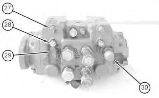
Illustration 15
30. Remove caps (27).
31. Remove connectors (28).
32. Remove fitting (29).
33. Remove adapter (30).
g01178123
Illustration 16
g00905035
Note: Mark the location of the notch in stud (31) by making a corresponding mark on the housing for installation purposes.
34. Use Tooling (A) to measure the distance from stud (31) to nut (32). Record the distance for assembly purposes.
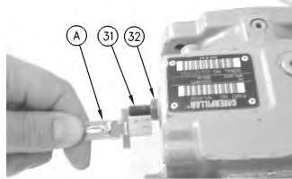
35. Remove stud (31) and nut (32).
36. Repeat Step 34 and Step 35 for the other stud.
Illustration 17
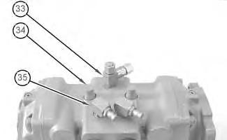
37. Remove connector (33).
38. Remove caps (34).
39. Remove fittings (35).
Illustration 18
40. Use Tooling (A) to measure the distance from studs (36) to nuts (37). Record the distance for assembly purposes.
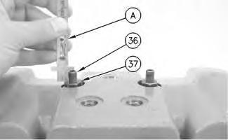
41. Remove studs (36) and nuts (37).
 g01178125
g00905224
g01178125
g00905224
Illustration 19
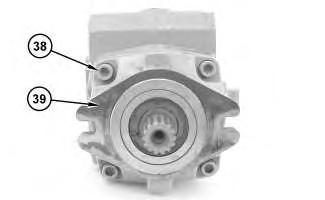
42. Remove bolts (38) from cover (39).
g01178127
Illustration 20
g00973868
43. Use a suitable lifting device, Tooling (C), Tooling (D), and Tooling (E) to raise the piston pump housing.
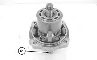
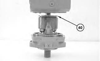
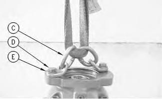
Illustration 21
g01178130
Note: Mark the port plates for assembly. Port plates are not interchangeable.
44. Remove port plate (40).
Illustration 22
45. Remove plug (41) and the O-ring seal.
Illustration 23
46. Remove slotted pin (42).
47. Repeat Step 45 and Step 46 for the other side.
Illustration 24
48. Remove the rotating assembly and swashplate (43).
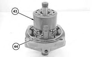
49. Remove linkage (44).

Illustration 25
50. Remove bearing assemblies (45) and (46).
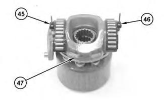
51. Remove swashplate (47).
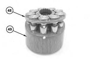
Illustration 26
Note: Mark the reaction plate assembly and the barrel.
52. Remove reaction plate assembly (48) from barrel (49).
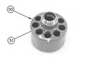
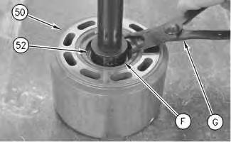
Illustration 27
53. Remove the retainer and shims (51) from barrel (50).
Personal injury can result from being struck by parts propelled by a released spring force.
Make sure to wear all necessary protective equipment.
Follow the recommended procedure and use all recommended tooling to release the spring force.
54. Place barrel (50) in a suitable press.
55. Use Tooling (F) and Tooling (G) to remove retaining ring (52) and spring (55).
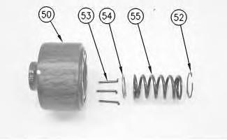
56. Remove washer (54).
57. Remove pins (53).
Illustration 28 g00973870 Illustration 29 g00905448Illustration 30 g00905648
58. Remove bearing races (56) from pins (57).
Illustration 31 g00905650
59. Remove O-ring seal (58).
60. Inspect dowel (59) for damage.
Illustration 32
g00905577
61. Use Tooling (B) to remove retaining ring (60).
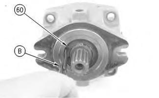
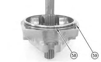
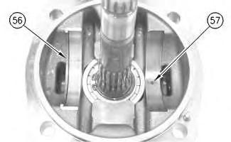
Illustration 33
62. Use Tooling (H) to remove seal (61).
Illustration 34
63. Use Tooling (B) to remove retaining ring (62).
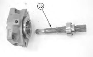
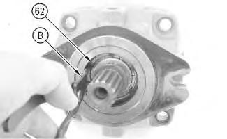
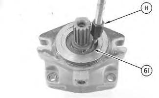
Illustration 35
64. Remove shaft (63).
Illustration 36
65. Use Tooling (J) to remove retaining ring (64).
Illustration 37
66. Use a suitable press and Tooling (K) to remove bearing (65).
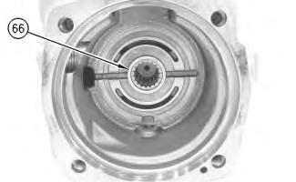
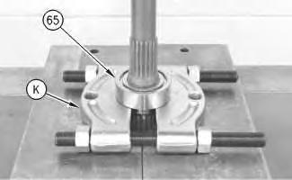
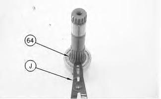
Illustration 38
67. Remove bearing (66).
Illustration 39
68. Remove actuator (67).
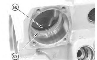
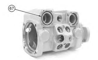
Illustration 40
69. Remove seal (68).
70. Remove liner (69).
71. Repeat Step 42 through Step 70 for the other end of the piston pump.
Copyright 1993 - 2019 Caterpillar Inc.
All Rights Reserved.
Private Network For SIS Licensees.
Shutdown SIS
Previous Screen
Product: SKID STEER LOADER
Model: 216B3 SKID STEER LOADER JXM
Configuration: 216B3 Skid Steer Loader JXM00001-UP (MACHINE) POWERED BY C2.2 Engine
Disassembly and Assembly
259B3 Compact Track Loader, 247B3 and 257B3 Multi Terrain Loaders and 216B3, 226B3, 236B3, 242B3 and 252B3 Skid Steer Loaders Power Train
Piston Pump (Hydrostatic) - Assemble
SMCS - 5070-016-H7
Assembly Procedure
Table 1
Required Tools
Illustration 1
g00906515
1. Install liner (69).
2. Install seal (68).
Illustration 2
g00906511
3. Install actuator (67).
Illustration 3
g00906134
4. Install bearing (66).
Suggest:
If the above button click is invalid.
Please download this document first, and then click the above link to download the complete manual.
Thank you so much for reading

Illustration 4
5. Raise the temperature of bearing (65).
6. Use a suitable press and Tooling (K) to install bearing (65).
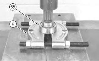
Illustration 5
7. Use Tooling (J) to install retaining ring (64).
Illustration 6
8. Install shaft (63).
g00906130 g00905698 g00905653