
216B3 SKID STEER LOADER
Shutdown SIS
Previous Screen
Product: SKID STEER LOADER
Model: 216B3 SKID STEER LOADER CD3
Configuration: 216B3 Skid Steer Loader CD300001-UP (MACHINE) POWERED BY C2.2 Engine
Disassembly and Assembly
259B3 Compact Track Loader, 247B3 and 257B3 Multi Terrain Loaders and 216B3, 226B3, 236B3, 242B3 and 252B3 Skid Steer Loaders Power Train
Piston Pump (Hydrostatic) - Assemble
SMCS - 5070-016-H7
Assembly Procedure
Table 1
Required Tools
Media Number -UENR0251-07 Publication Date -01/07/2018 Date Updated -11/07/2018 i02362815
Tool Part Number Part Description Qty A 9U-7289 Ruler 1 B 1P-1861 Retaining Ring Pliers 1 F 1P-0510 Driver Gp 1 G 1P-1854 Retaining Ring Pliers 1 J 1P-1860 Retaining Ring Pliers 1 K 8H-0663 Bearing Puller Gp 1 L 2P-8301 Seal Guide 1 M 6V-2055 Grease 1 N 1U-6395 Grease 1 P 9S-3263 Thread Lock Compound 1
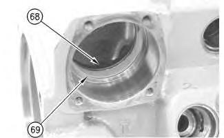
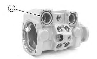
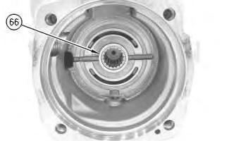 Illustration 1
g00906515
1. Install liner (69).
2. Install seal (68).
Illustration 2
g00906511
3. Install actuator (67).
Illustration 3
g00906134
4. Install bearing (66).
Illustration 1
g00906515
1. Install liner (69).
2. Install seal (68).
Illustration 2
g00906511
3. Install actuator (67).
Illustration 3
g00906134
4. Install bearing (66).
Illustration 4
5. Raise the temperature of bearing (65).
6. Use a suitable press and Tooling (K) to install bearing (65).
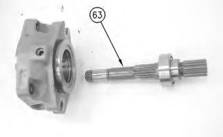
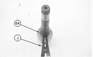
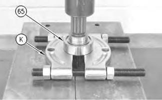
Illustration 5
7. Use Tooling (J) to install retaining ring (64).
Illustration 6
8. Install shaft (63).
g00906130 g00905698 g00905653Illustration 7
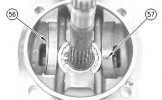
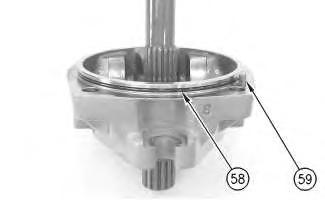
Illustration 8
 g00905582
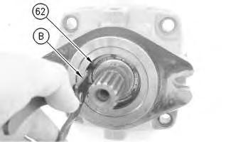
9. Use Tooling (B) to install retaining ring (62).
g00905650
10. Dowel (59) must be aligned with the piston pump housing during assembly.
11. Install O-ring seal (58).
Illustration 9
g00905648
12. Install bearing races (56) on pins (57).
g00905582
9. Use Tooling (B) to install retaining ring (62).
g00905650
10. Dowel (59) must be aligned with the piston pump housing during assembly.
11. Install O-ring seal (58).
Illustration 9
g00905648
12. Install bearing races (56) on pins (57).
Improper assembly of parts that are spring loaded can cause bodily injury.
To prevent possible injury, follow the established assembly procedure and wear protective equipment.
13. Install pins (53).
14. Install washer (54).
15. Place barrel (50) in a suitable press.
16. Use Tooling (F) and Tooling (G) to install spring (55) and retaining ring (52).
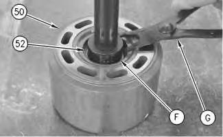
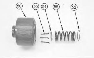 Illustration 10
g00905448
Illustration 11
g00973870
Illustration 10
g00905448
Illustration 11
g00973870
Illustration 12 g00905445
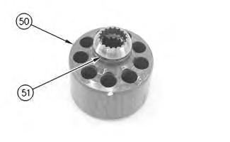
17. Install the shims and retainer (51) to barrel (50).
Illustration 13 g01178137
Note: Align the reaction plate assembly with the barrel.
18. Install reaction plate assembly (48) to barrel (49).
Illustration 14
19. Install swashplate (47).
20. Install bearing assemblies (45) and (46).
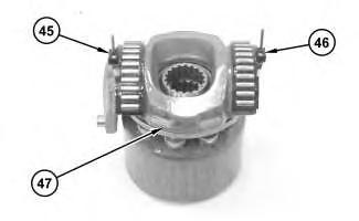
g01178135
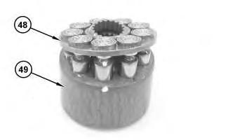
Illustration 15 g01178133
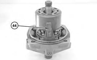
21. Install linkage (44).
22. Install the rotating assembly and swashplate (43).
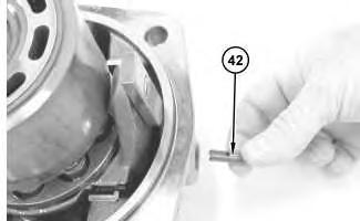
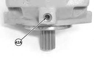
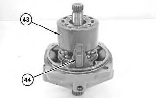
Illustration 16 g01180099
Illustration 17
g0117813223. Note the orientation of linkage (44).
24. Pin (42A) must be centered in the hole in the pump housing.
25. Install slotted pin (42) so that the slotted pin engages pin (42A).
26. Install the plug and O-ring seal (41).
27. Repeat Step 24 through Step 26 for the other side.
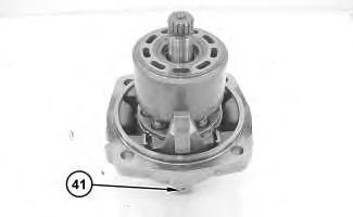 Illustration 18
g01178131
Illustration 19 g01180101
Illustration 20 g01180102
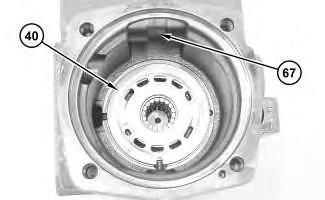
Note: The port plates are marked for assembly. Port plates are not interchangeable.
28. Apply Tooling (M) to port plate (40).
29. Align port plate (40) with the piston pump housing.
30. Install port plate (40).
31. Position linkage (44) in order to connect with actuator (67) during assembly.
32. Assemble the cover to the piston pump housing.
33. Repeat Step 1 through Step 32 for the other end of the piston pump.
Illustration 21
34. Apply Tooling (N) to seal (61).
35. Use Tooling (L) to install seal (61).
g01180104
Illustration 22
g00906796
36. Use Tooling (B) to install retaining ring (60).
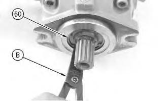
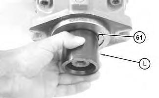
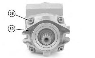
Illustration 23
37. Install bolts (38) to cover (39).
Illustration 24 g00905224
38. Position stud (36) and nut (37).
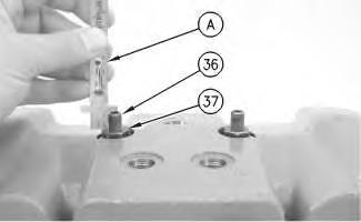
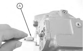
39. Use Tooling (A) to measure the distance from stud (36) to nut (37). Set the distance to the recorded measurement from the disassembly.
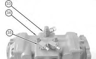
Illustration 25
40. Install fittings (35).
g01178127
g01180160
41. Install caps (34).
42. Install connector (33).
Note: Align the mark on the housing with the notch in stud (31).
43. Install stud (31) and nut (32). Set the distance to the recorded measurement from the disassembly.
44. Use Tooling (A) to measure the distance from stud (31) to nut (32). Tighten the nut to a torque of 30 ± 2 N·m (22 ± 1 lb ft).
45. Repeat Step 43 and Step 44 for the other stud.
46. Install adapter (30).
47. Install fitting (29).
48. Install connectors (28). Tighten the connectors to a torque of 22 ± 1 N·m (16 ± 1 lb ft).
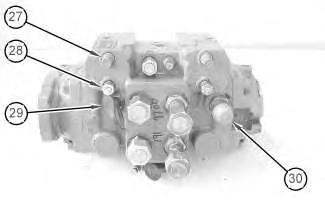
49. Install caps (27).
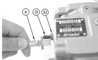 Illustration 26 g00905035
Illustration 27 g01178123
Illustration 26 g00905035
Illustration 27 g01178123
Improper assembly of parts that are spring loaded can cause bodily injury.
To prevent possible injury, follow the established assembly procedure and wear protective equipment.
Note: Keepers (21) are marked for assembly. Do not mix keepers (21).
50. Install spacer (25).
51. Install spring retainer (24).
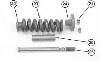
52. Install spring (23).
53. Install spring retainer (22).
54. Install shaft (26).
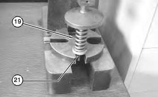
Illustration 28 g01054370 Illustration 29 g0105436855. Place actuator assembly (19) in a suitable press.
56. Install keepers (21).
Illustration 30
g00905018
57. Install O-ring seal (20) on actuator assembly (19).
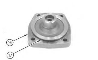
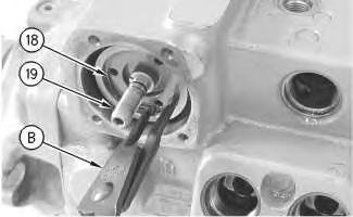
Illustration 31
58. Install actuator assembly (19).
g00904933
59. Use Tooling (B) to install retaining ring (18).
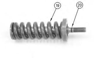
Illustration 32
60. Install O-ring seal (17) to cover (16).
Illustration 33
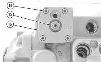
61. Install cover (16).
62. Install nut (15).
63. Install screws (14).
Illustration 34
64. Use Tooling (A) to measure the distance from the stud to the nut. Set the distance to the recorded measurement from the disassembly.
 g00904930
g00904929
g01178122
g00904930
g00904929
g01178122
Illustration 36
65. Install O-ring seal (10) to plug (8).

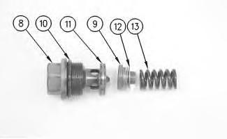
66. Install seal (11) to plug (8).
67. Install spring (13).
68. Install shims (12).
69. Install seat (9).
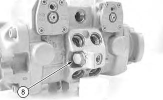
Illustration 35 g00903503 g00903502 Illustration 37 g0090350070. Install plug (8) for the charge relief valve. Tighten the plug to a torque of 70 ± 4 N·m (52 ± 3 lb ft).
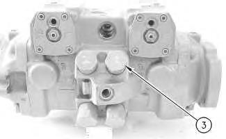
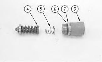
71. Install back up ring (7) to cover (3).
72. Install O-ring seal (6) to cover (3).
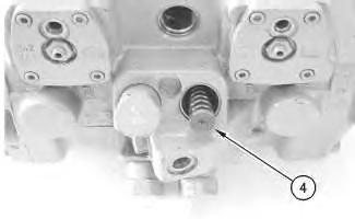
73. Note the orientation of spring (5).
74. Install seat (4).
Illustration 38 g00903467 Illustration 39 g00903461g00903457
Improper assembly of parts that are spring loaded can cause bodily injury.
To prevent possible injury, follow the established assembly procedure and wear protective equipment.
75. Install the spring and cover (3) for the crossover relief valve. Tighten the cover to a torque of 160 ± 8 N·m (118 ± 6 lb ft).
76. Repeat Step 71 through Step 75 for the other covers.
Illustration 41
g00903455
77. Install speed sensing valve (2). Tighten the valve to a torque of 50 ± 3 N·m (37 ± 2 lb ft).
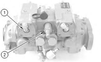
78. Install the fittings and connectors (1).
End By:
a. Install the piston pump. Refer to Disassembly and Assembly, "Piston Pump - Install".
Copyright 1993 - 2019 Caterpillar Inc.
All Rights Reserved.
Private Network For SIS Licensees.
Sun Oct 6 23:29:26 UTC+0800 2019
Illustration 40Shutdown SIS
Previous Screen
Product: SKID STEER LOADER
Model: 216B3 SKID STEER LOADER CD3
Configuration: 216B3 Skid Steer Loader CD300001-UP (MACHINE) POWERED BY C2.2 Engine
Disassembly and Assembly
259B3 Compact Track Loader, 247B3 and 257B3 Multi Terrain Loaders and 216B3, 226B3, 236B3, 242B3 and 252B3 Skid Steer Loaders Power Train
Piston Pump (Hydrostatic) - Install
SMCS - 5070-012-H7
Installation Procedure Table 1 Required Tool
(1)
Media Number -UENR0251-07 Publication Date -01/07/2018 Date Updated -11/07/2018 i07376431
Tool Part Number Part Description Qty A 247-4296 Pump Support 1 B 138-7575 Link Bracket 1 C 159-3327(1) Wrench Adapter 1 387-9124(2) Wrench Adapter 1
For use with hex head bolts.
For use with 12 point head bolts
(2)
Illustration
g01053175
1. Use a suitable lifting device, Tooling (B), and Tooling (A) to support piston pump (5).
2. Position piston pump (5). The weight of the piston pump is approximately 61 kg (134 lb).
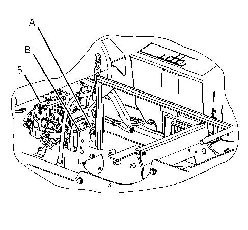
1
Illustration 2
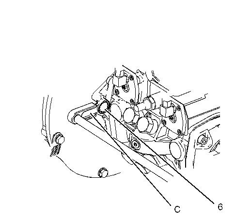
g01053307
3. Use Tooling (C) to install bolt (6). Tighten bolts (6) to a torque of 160 ± 30 N·m (118 ± 22 lb ft).
Note: Refer to Service Magazine, SEPD1272, "A New Bolt Is Used To Fasten The Hystat Pump To The Engine" for bolt replacement information.
4. Repeat Step 3 for the other side.
5. Remove Tooling (A) and (B) from piston pump (5).
6. Connect hose (4).
7. Tighten clamp (3).
8. Connect hose assemblies (2).
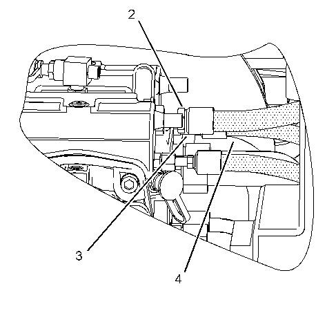
3
Illustration
g01051393
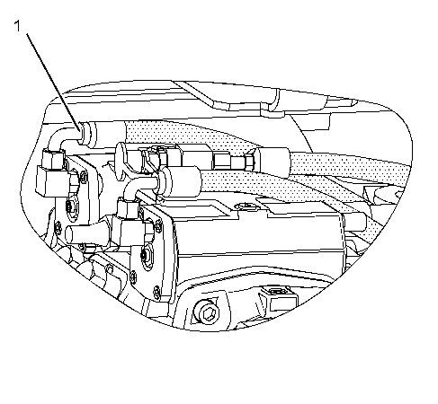
Illustration 4 g01051392
(1).
the gear pump.
Install hydraulic tank. Copyright 1993 - 2019 Caterpillar Inc. All Rights Reserved. Private Network For SIS Licensees. Sun Oct 6 23:30:25 UTC+0800 2019
9. Connect hose assemblies
End By: a. Install
b.
Suggest:
If the above button click is invalid.
Please download this document first, and then click the above link to download the complete manual.
Thank you so much for reading

Shutdown SIS
Previous Screen
Product: SKID STEER LOADER
Model: 216B3 SKID STEER LOADER CD3
Configuration: 216B3 Skid Steer Loader CD300001-UP (MACHINE) POWERED BY C2.2 Engine
Disassembly and Assembly
259B3 Compact Track Loader, 247B3 and 257B3 Multi Terrain Loaders and 216B3, 226B3, 236B3, 242B3 and 252B3 Skid Steer Loaders Power Train
Control Manifold and Solenoid (Parking Brake) - Remove and Install
SMCS - 5264-010; 5479-010
Removal Procedure
Table 1
Required Tools
Start By:
a. Release the hydraulic system pressure. Refer to Disassembly and Assembly, "Hydraulic System Pressure - Release".
b. Tilt the cab. Refer to Disassembly and Assembly, "Cab - Tilt".
Note: SERVICE DATA: TOOLING (ZZ) WILL NOT BE IDENTIFIED IN PHOTOGRAPHS IN THE REMOVAL OR THE INSTALLATION. THIS TOOLING IS SHOWN IN ORDER TO ASSIST THE EXPERIENCED SERVICEMAN.
Number -UENR0251-07 Publication Date -01/07/2018 Date Updated -11/07/2018
Media
i02787466
Tool Part Number Part Description Qty ZZ 6V-9508 Face Seal Plug (11/16 - 16 THD) 3 6V-9829 Cap Assembly (11/16 - 16 THD) 3 6V-9509 Face Seal Plug (13/16 - 16 THD) 2 6V-9830 Cap Assembly (13/16 - 16 THD) 2