Mini Excavators CX16B and CX18B
SERVICE MANUAL
CNH Cre 9-88670

This service manual has been prepared in order to increase repair quality, providing to the technicians the elements for a good knowledge of the product and showing the proper procedures to carry out the maintenance operations. We recommend to thoroughly read the content and follow it when necessary.
It is a concise guide. It covers construction features, operation principle, troubleshooting, disassembly and assembly of components and repair action.
Using this manual in systematic and rational way it is possible to reduce the repairing errors and delay that could cause machine stop with a detriment of cost management.
The information quoted in this service manual are supplied also to be used for training aids. Therefore it is advisable to be used in the training of new personnel that will be employed in the machine maintenance.
All the information, illustrations and specifications contained in this service manual are based on the latest product information available at the time of publication. The dealer reserves the right to makes changes at any time without notice to this service manual for technical or trading reasons.
This service manual is carried out in loose-leaf and therefore can be easily kept up-to-date. The personnel in charge is responsible for updating the manual and will insert the changes or supplements that the Dealer will issue to its service organisation.
In this service manual, symbols and indications are used to draw the attention on important points for safety and quality.
This safety symbol is used for important safety message. When you see this symbol, be alert to the potential for personal injury. Strictly follow the recommended precautions.

Reading this service manual you can find indications as “IMPORTANT” or “NOTE” that have the following meaning:
• IMPORTANT
Indicates a situation which, if not avoided, could caused damages to the machine.
• Note Indicates supplementary technical information or know-how.
This service manual is divided into ten Sections. The Section names and its contents are as below. To fully use this service manual it is essential to understand how it is organised. Therefore, in order to speed up the searching of wished subject, it is advisable to carefully read this chapter.
SECTION 1 - HOW TO USE
Begin to read first this Section to know the manual composition. This will help you for subject searching.
SECTION 2 - SAFETY RULES
Indication on how to avoid dangerous situation during the use and maintenance are given in this Section. Furthermore safety decals and related indications used on the machine are listed on this Section.
SECTION 3 - PRELIMINARY
This Section contains the information related to general precautions for repairs and escaping procedure in can of emergency.
SECTION 4 - SPECIFICATION
This Section quotes the specification and data of the machine.
SECTION 5 - TOOLS
This Section contains the list of special tools.
SECTION 6 - STANDARD MAINTENANCE TIME TABLE
SECTION 7 - MAINTENANCE STANDARDS AND TEST PROCEDURES
SECTION 8 - HYDRAULIC SYSTEM
This Section describes the operation of the machine from hydraulic point of view.
SECTION 9 - ELECTRICAL SYSTEM
This Section describes the electric system of the machine and the connection with the electrical users.
SECTION 10 - ATTACHMENT
This Section describes the attachments and its components and maintenance rules with related disassembly/ assembly.
SECTION 11 - UPPER STRUCTURE
This Section contains the information related to the operation principle of the system, of the assemblies and their components located on the machine upper frame. Furthe more the assembly/disassembly procedures of main devices are quotated.
SECTION 12 - TRAVEL SYSTEM
This Section contains the information related to the operation principle of the system, of the assemblies and their components located on the machine travel system. Further more the assembly/disassembly procedures of main devices are quotated.
SECTION 13 - TROUBLESHOOTING HYDRAULIC SYSTEM
In this section information is provided for troubleshooting the hydraulic system.
SECTION 14 - TROUBLESHOOTING ELECTRICAL SYSTEM
In this section information is provided for troubleshooting the electric system.
SECTION 15 - TROUBLESHOOTING ENGINE
In this section information is provided for troubleshooting the engine.
SECTION 16 - ENGINE
This section descibes specifications, performance, measurament, inspection, disassembly/assembly and service data of engine.
The manual is divided into sections, each of them quotes a specific portion of the machine or a specific related subject.
Some sections (those related to main mechanical assembly) are divided into:
• Operation Principle
• Disassembly/Assembly
In the Operation Principle, the assemblies and their components are described with technical data.
In the Disassembly and Assembly section the procedures are described to perform, repair or overhaul, with special tools required and technical data.
Page numbers have the following meaning:
• example:
2 - 1
Consecutive page number. Section number.
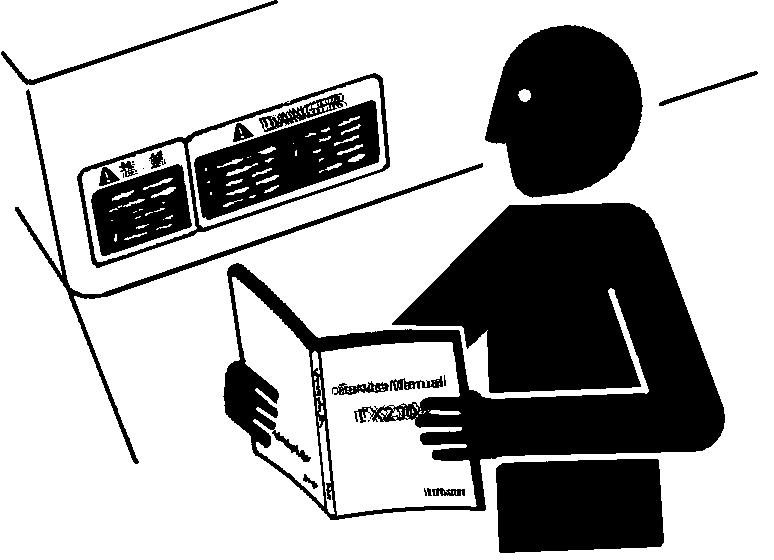
Read the Operation and Maintenance Instruction Manual carefully before starting, operating, maintaining, fuelling or servicing the machine. Carefully read the explanation to each and all safety signs in the special section of this Manual before starting, operating, maintaining, fuelling or servicing the machine.
Machine-mounted safety plates are colour coded yellow with black borders when they refer to points where special WARNING must be paid and failure to observe them may cause a serious DANGER to the integrity of machine operators.
They are white with red borders and black lettering when they refer to a FORBIDDEN practice.
It is fundamental that all machine operators know very well the meaning of each safety plate as this considerably decreases operating hazards and accidents.
Do not allow unauthorised personnel to operate or service this machine.
Do not wear rings, wrist watches, jewellery, loose or hanging garments, such as ties, torn clothing, scarves, unbuttoned or unzipped jackets that can get caught in moving parts.
Wear certified safety clothes such as: hard hat, noslip footwear, heavy gloves, ear protection, safety glasses , reflector vests, respirators every time the job requires it.
Ask your employer about safety regulations in force and protective equipment.
Always keep the operator’s compartment, step plates, grab-rails and handles clean and clear of foreign objects, oil, grease, mud or snow to minimise the danger of slipping or stumbling. Remove mud or grease from your shoes before operating the machine.
Do not jump on or off the machine. Always keep both hands and one foot, or both feet and one hand in contact with steps and/or grab rails.
Do not use controls or hoses as hand holds. Hoses and controls are movable parts and do not provide solid support.
Besides, controls may be inadvertently moved and cause unexpected movement of the machine or its attachments.
Never operate the machine or its attachments from any position other than sitting in the driver’s seat.
Keep head, body, limbs, hands and feet inside the operator’s compartment at all times to reduce exposure to external hazards.
Be careful of possible slippery conditions of the steps and hand rails as well as of the ground around the machine.
Wear protective boots or shoes with the soles made of highly no-slip rubber.
Do not leave the machine until it has come to a complete stop.
Always check height, width and weight limitations which may be encountered in the working site and ensure the machine does not exceed them.
Assess exact paths of gas ducts, water mains, telephone lines, sewers, overhead and underground electric lines and all other possible obstacles.
Such paths should be opportunely defined by competent Authorities.
If necessary, require that the service is interrupted or said installations are moved prior to starting the work.
You must know the working capacity of the machine.
Define the rear upperstructure swing area and provide for opportune barriers to prevent access into it.
Never exceed machine lifting capacity. Remain within the limits shown in the loading capacity chart located on the machine.
Never start or operate a failed machine. Walk all around the machine before mounting. Before operating the machine, make sure that any possible dangerous condition has been properly removed.
Before starting machine, check that steering and attachment controls are in the neutral position and the safety lever is in the LOCK position. Immediately report any malfunction of parts or systems to the maintenance managers for proper action.
Prior to starting the engine, check, adjust and lock the driver’s seat for maximum riding comfort and control accessibility.
Prior to operating the machine and/or its attachments, check that bystanders are outside the machine operating range. Sound the horn.
Obey all hand signals, safety indications and signs.
Due to the presence of flammable fluids, never check fuel level, refuel, charge the batteries or use the starting fluid in the presence of smoking materials, open flames or sparks.
Ensure that nobody is within the excavator operating area before starting the machine, swinging the upper structure or moving in any direction. Adjust all rear-view mirrors for maximum visibility of the area behind the machine.
Ensure that engine speed is appropriate to the job to be carried out.
If any hydraulic control or system exhibits erratic performance or responds abnormally, have the machine checked for air in the system.
Air in these circuits may cause incorrect movements with consequent accident hazard.
Refer to the Operation and Maintenance Instruction Manual about corrective action to be taken.
Do not run the engine of this machine in closed buildings without proper ventilation capable to remove harmful exhaust gases which concentrate in the air.
Keep the operator’s compartment free of foreign objects, especially if not firmly secured. Never use the machine to transport objects, unless proper securing points are provided.
Do not carry riders on the machine.
Study and familiarise with escape routes alternative to normal exit routes.
For your personal safety, do not climb on or off the machine while it is in motion.
Make sure that bystanders are clear of the machine operating range before starting the engine and operating the attachment. Sound the horn. Obey all hand signals, safety indications and signs.
When backing, always look to where the machine is to be moved. Be alert of the position of bystanders. Should someone enter the work area, stop the machine.
Maintain a safe distance from other machines or obstacles to ensure required visibility conditions. Always give way to loaded machines.
Maintain a clear vision of the surroundings of the travel or work area at all times.
Keep cab windows clean and repaired. When pulling loads or towing through a cable or chain, do not start suddenly at full throttle. Take-up
slack carefully.
Avoid kinking or twisting chains or cables. Carefully inspect cables or chains for flaws or problems before proceeding.
Do not pull through a kinked chain or cable as the high anomalous stresses existing in this condition may induce failures in the kinked portion. Always wear heavy gloves when handling chains or cables.
Chains and cables should be securely anchored using suitable hooks. Anchor points should be strong enough to withstand the expected load. Keep anyone clear of anchor points and cables or chains. Do not pull or tow unless the operator’s compartments of the machines involved are properly protected against possible backlash in case of cable or chain failure or detachment. Be alert of soft ground conditions close to newly constructed walls.
The fill material and machine weight may cause the wall to collapse under the machine. In darkness, check area of operation carefully before moving in with the machine. Use all lights provided.
Do not move into low visibility areas.
If the engine tends to slow down and stall for whatever reason under load or at idle, immediately report this problem to the maintenance managers for proper action.
Do not operate the machine until this condition is corrected.
Regularly check all exhaust system components, as exhaust fumes are toxic for the operator. Operators must know the performance of the machine they are driving.
When working on slopes or near sudden level drops in the terrain, pay attention not to lose adherence and avoid loose soft ground since overturn or loss of machine control could result.
If noise level is high and exceeds 90 dB(A) over 8 hours at the operator’s ear, wear approved ear protection in compliance with local regulations. Do not operate the machine if you are extremely tired or feel ill.
Be especially careful towards the end of the working shift.
Where removable counterweights are provided, do not operate the machine if they have been removed.
When operating the machine, keep in mind height limits of overhead doors, arches, overhead cables
and lines as well as width limits of corridors, roads and narrow passages.
Also, get to know load limits of the ground and paving type of the ramps you are to work on. Beware of fog, smoke or dust that obscure visibility.
Always inspect the working area to identify potential risks such as: inclines, overhangs, trees, demolition bble, fires, ravines, steep slopes, rough terrain, ditches, crowns, ridge trenches, diggings in traffic areas, crowded parking lots, crowded service areas, fenced zones. In such conditions, proceed with extreme care.
Whenever possible, avoid crossing over obstacles such as very rough terrain, rocks, logs, steps, ditches, railroad tracks.
When obstructions must be crossed, do so with extreme care and at a square angle, if possible. Slow down.
Ease up to the break-over point, pass the balance point slowly and ease down the other side also using the attachment, if necessary.
To overcome deep trenches or sinking ground, place the machine perpendicular to the obstacle, drastically reduce ground speed and start crossing using also the attachment if necessary, only after assessing that ground conditions allow the traverse safely and without risks.
The gradient you may attempt to overcome is limited by factors such as ground conditions, load being handled, machine type and speed, and visibility.
There is no substitute for good judgement and experience when working on slopes. Avoid operating the attachment too close to an overhang or high wall, either above or below the machine.
Beware of caving edges, falling objects and landslides. Remember that such hazards are likely to be concealed by bushes, undergrowth and such. Avoid faggots, bushes, logs and rocks.
Never drive over them, nor over any other surface irregularities that discontinue adherence or traction with the ground, especially near slopes or drop-offs.
Be alert to avoid changes in adherence conditions that could cause loss of control.
Work with extreme care on ice or frozen ground and on stepped slopes or near drop-offs. The word “bulldozing” generally refers to work in virgin rough terrain, characterised by the presence of all the perils and risks listed above.
We emphasise the danger represented in these conditions by large tree limbs (possibly falling on the machine) and large roots (which may act as a leverage under the machine when up-rooted and cause the unit to overturn).
Position the machine dependent upon the loading and unloading areas in order to swing leftwards to load to obtain best visibility.
Never use the bucket or attachment as a man lift or carry riders.
Never use the machine as a work platform or scaffolding.
The machine must not be improperly used for works not consistent with its features (such as pushing railway cars, trucks or other machines). Always pay attention to people within the machine operating range.
Never move or stop the bucket, other loads or the attachment above ground personnel or truck cabs. Ensure the truck driver is in a safe place before loading the truck.
Load trucks from side or rear.
Use only the type of bucket recommended considering machine type, materials to be handled, material piling up and loading characteristics, ground type and other typical conditions of the work to be performed.
When travelling with a loaded bucket, keep it as rolled-back as possible. Keep boom and arm as low as possible.
Ground speed should be adequate to the load and ground conditions.
The load must always be properly arranged in the bucket; move with extreme care when transporting oversize loads.
Do not lift and move the bucket overhead where persons are standing or working, nor downhill when working on a slope as this would decrease machine stability. Load the bucket from the uphill side.
Loads to be raised using the machine should be exclusively hooked to the hitch specially provided. The excavator is no lifting and transportation means, therefore it should not be used to position loads accurately.
Should it be exceptionally used to lift and lay building components, special caution must be taken as follows:
• The machine should necessarily be equipped with the special option supplied by Dealer Follow also safety rules for the excavator used as lifting means.
• Secure the loads to be raised using cables or chains fastened with appropriate hooking mechanisms.
• Nobody should be allowed to remain under the raised load or within the excavator operating range for any reason whatever.
Never exceed specified loading capacity. Incorrect fastening of slings or chains may cause boom/ arm failure or failure of the lifting means with consequent bodily injuries and even death. Always ensure that slings and chains used for lifting are adequate to the load and in good condition.
All loading capacities are referred to the machine on a level surface and should be disregarded when working on a slope. Avoid travelling across slopes. Proceed from uphill downhill and vice-versa.
If machine starts slipping sideways when on a slope, lower the bucket and thrust bucket teeth into the ground.
Working on slopes is dangerous. Grade the working area if possible.
Reduce work cycle time if it is not possible to grade the working area.
Do not move full bucket or a load from uphill downhill as this would reduce machine stability. Do not work with the bucket turned to the uphill side.
Do not work with the bucket turned uphill as counterweights protruding downhill would reduce machine stability on the slope and increase risk of overturning.
We recommend to work on slopes with the bucket downhill, after checking machine stability with the bucket empty and attachment retracted, by slowly swinging the upper structure by 360 ° Position the carriage at a right angle relative to slopes, hanging walls, etc. to exit the working area easily.
Be aware when the upperstructure is turned by 180 ° , steering and travel controls are reversed. Properly judge ground conditions with particular attention to consistency of the area you are going to work on.
Keep the machine sufficiently far from the ditch edge.
Never dig under the machine.
Should it be necessary to dig under the machine, always ensure that digging walls are opportunely propped up against landslide to prevent the machine from falling into the trench.
Do not swing the upperstructure, raise the load or brake abruptly if not required. This may cause accidents.
Prior to beginning the work near gas distribution mains or other public utilities:
• Contact the company owner of the gas mains or its nearest branch before starting the work. Look up the number in the telephone directory.
• Define together which precautions should be taken to guarantee work safety.
• Decrease work speed. Reaction time could be too slow and distance evaluation wrong.
•W hen working near gas mains or other public utilities installations, appoint a person in charge of signalling duties. This person will have the responsibility of observing the machine, any part of it and/or the load approaching the gas mains from a standpoint more favourable than the Operator’s. This signal man (flag-man) must be in direct communication with the Operator and the Operator must pay undivided attention to the signals supplied.
• The gas distributing Company, if previously advised and involved in the work, as well as machine Operator, Owner and/or any natural person or legal entity having rent or leased the machine or being responsible at the time by contract or by law, are liable for the adoption of the necessary precautions.
Working near electric lines can be very dangerous, therefore some special precautions must be observed.
Within this Manual, “work near electric lines” means when the attachment or load raised by the excavator (in any position) may reach the minimum safety distance established by local or international Safety Regulations.
To work without risks, keep maximum possible distance from electric lines and never trespass minimum safety distance.
Ensure that local or national safety regulations concerning work near electric lines are observed. Prior to beginning the work near electric lines:
• Contact the Company owner of the electric lines or its nearest branch before starting the work. Look up the in the telephone directory.
• Define together with the Company representative which precautions should be taken to guarantee work safety.
• All electric lines should be considered as operative live lines even though it might be well known that the line in question is out of work and
visibly connected to the ground.
• The Electric Power Company, if previously advised and involved in the work, as well as machine Operator, Owner and/or any natural person or legal entity having rent or leased the machine or being responsible at the time by contract or by law, are liable for the adoption of the necessary precautions.
• Decrease work speed. Reaction time could be too slow and distance evaluation wrong.
•W arn all ground personnel to keep clear of the machine and/or load at all times. If the load has to be guided down for laying, consult the Electric Power Company to know which precautions should be taken.
• Appoint a person in charge of signalling duties. This person will have the responsibility of observing the machine, any part of it and/or the load approaching the electric lines from a standpoint more favourable than the Operator’s. This signal man (flag-man) must be in direct communication with the Operator and the Operator must pay undivided attention to the signals supplied.
When working in or near pits, in ditches or very high walls, check that the walls are sufficiently propped up to avoid cave-in hazards.
Pay the utmost attention when working near overhang walls or where landslides may take place. Make sure that the support surface is strong enough to prevent landslides.
When digging, there is the risk of cave-ins and landslides.
Always check ground conditions and conditions of the material to be removed.
Support everywhere it is required to prevent possible cave-ins or landslides when:
•d igging near previous trenches filled with material,
• digging in bad ground conditions,
• digging trenches subject to vibration from railroads, working machines or highway traffic.
When the machine is to be stopped for whatever reason, always check that all controls are in the neutral position and that the safety lever is on the lock position to guarantee risk-free start-up.
Never leave the machine unattended with the engine running.
Prior to leaving the driver’s seat, and after making
sure that all people are clear of the machine, slowly lower the attachment until resting it safely to the ground.
Retract possible auxiliary tools to the closed safety position.
Check that all controls are in the neutral position. Move engine controls to the shut-down position. Switch off the key-start switch.
Consult the Operation and Maintenance Instruction Manual.
Park the machine in a non-operating and no-traffic area.
Park on firm level ground. If this is not possible, position the machine at a right angle to the slope, making sure there is no danger of uncontrolled sliding.
If parking in traffic lanes cannot be avoided, provide appropriate flags, barriers, flares and other signals as required to adequately warn the oncoming drivers.
Always switch off the key-start switch before cleaning, repairing or servicing, or parking the machine to prevent accidental unauthorised start-up. Never lower the attachment or auxiliary tools other than from sitting in the operator’s seat.
Sound the horn. Make sure that nobody is within the machine operating range. Lower the attachment slowly.
Securely block and lock the machine every time you leave it unattended. Return keys to the safe place previously agreed upon.
Perform all necessary operations for stopping as detailed in the Operation and Maintenance Instruction Manual.
Drive the machine far from pits, trenches, rocky hanging walls, areas with overhead electric lines, and slopes before stopping it at the end of the working day.
Align the upperstructure to the tracks in order to allow to easily get on and off the driver’s compartment.
Move all controls to the position specified for machine stopping. Refer the Operation and Maintenance Instruction Manual.
Never park on an incline without accurately blocking the machine to prevent unexpected movement. Follow stopping instructions contained in the Operation and Maintenance Instruction Manual.
Carefully read the Operation and Maintenance Instruction Manual before starting, operating, maintaining, fuelling or servicing the machine in any manner.
Read all safety plates mounted on the machine and observe instructions they contain before starting, operating, repairing, fuelling or servicing the machine.
Do not allow unauthorised personnel to repair or service the machine.
Follow all recommended maintenance and service procedures.
Do not wear rings, wrist watches, jewellery, loose or hanging garments, such as ties, torn clothing, scarves, unbuttoned or unzipped jackets that can get caught in moving parts.
Wear certified safety clothes such as: hard hat, noslip footwear, heavy gloves, ear protection, safety glasses, reflector vests, respirators when required.
Ask your employer about safety regulations in force and protective equipment.
Do not use controls or hoses as hand holds. Hoses and controls are movable parts and do not provide solid support.
Besides, controls may be inadvertently moved and cause unexpected movement of the machine or its attachments.
Do not jump on or off the machine. Always keep both hands and one foot, or both feet and one hand in contact with steps and/or grab rails. Never service the machine with someone sitting in the driver’s seat, unless this person is an authorised operator assisting in the maintenance being carried out.
Keep the operator’s compartment, step plates, grab rails and handles clear of foreign objects, oil, grease, mud or snow to minimise the danger of slipping or stumbling.
Clean mud or grease from your shoes before climbing on the machine or driving it.
Never attempt to operate the machine or its attachments from any position other than sitting in the operator’s seat.
Keep the driver’s seat free from foreign objects, especially if these are not secured. Should it be necessary to move the attachment for maintenance purposes, do not raise or lower the
attachment from any other position than sitting in the operator’s seat.
Before starting the machine or moving its attachment, sound the horn and require that nobody remains near the machine. Raise the attachment slowly.
Always lock all moving components or parts of the machine that must be lifted for maintenance purposes using adequate external means as required by local and national regulations.
Do not allow anyone to pass or stay near or below a raised attachment. If you are not absolutely sure about your safety, do not stay or walk under a raised attachment.
Do not place head, body, limbs, hands, feet or fingers near articulated cutting edges deprived of the necessary guards, unless they are suitably and safely locked.
Never lubricate, repair or adjust the machine with the engine running, except when this is specifically required by the Operation and Maintenance Instruction Manual.
Do not wear loose clothing, jewellery near rotating parts.
When service or maintenance require access to areas that cannot be reached from the ground, use a ladder or step platform conforming to local or national regulations to reach the working area. If such means are not available, use machine grab rails and steps. Always perform all service or maintenance work with the greatest care and attention.
Shop and/or field service platforms or ladders should be manufactured and maintained in accordance with local or national safety regulations in force.
Disconnect batteries and label all controls to warn that service work is in progress, according to local and national safety regulation requirements. Block the machine and all attachments to be raised according to local and national safety regulation requirements.
Do not check or fill fuel tanks or install batteries near burning or smoking materials and open flames due to the presence of flammable vapours. The fuel filler pipe nozzle must be constantly kept in contact with the filler neck and this even before fuel starts flowing in.
Keep this contact from the beginning to the end of the fuelling operation to avoid possible generation of sparks due to static electricity.
Use a truck or trailer to haul a failed machine.
Should it be necessary to tow it, provide for suitable danger signals as required by the local norms and regulations and observe recommendations given in the Operation and Maintenance Instruction Manual.
Load/unload the machine on firm level ground providing safe support to the wheels of the truck or trailer. Use strong access ramps, with adequate height and angle.
Keep the trailer flatbed free of mud, oil or slippery materials.
Tie the machine securely to the trailer and block carriages and upperstructure.
Never align holes or slots using your fingers; always use appropriate aligning tools. Remove all sharp edges and burrs from re-worked parts.
Use only approved and effectively grounded auxiliary power sources for heaters, battery chargers, pumps and similar equipment to reduce electrical shock hazard.
Lift and handle heavy components using hoisting devices of appropriate capacity. Ensure the parts are supported by appropriate straps and hooks.
Use lifting eyes provided to this aim. Pay attention to bystanders near the lifting area. Never pour gasoline or diesel fuel into open containers.
Never use gasoline, solvents or other flammable fluids to clean parts.
Use proprietary certified non-flammable, non-toxic solvents only.
When using compressed air to clean parts, wear safety glasses with side shields. Limit pressure to max. 2 bars, in accordance with local and national safety regulations in force.
Do not run the engine of this machine in closed buildings without proper forced ventilation capable to remove toxic exhaust gases concentrating in the air.
Do not smoke, nor allow open flames or sparks nearby while refuelling the unit or handling highly flammable materials.
Do not use open flames as light sources to look for leaks or inspect anywhere on the machine.
Make sure that all mechanical tools provided are in good condition at all times.
Never use tools with mushroomed or damaged heads. Always wear eye protections with side shields.
Move with extreme care when working under, on
or near the machine or its attachments.
In case of attachment tests during which the engine should be kept running, a qualified operator must sit in the driver’s seat at all times while the mechanic is at work.
Keep hands and clothes far OFF moving parts. Stop the engine and move the safey lever to the lock position before starting adjusting or repairing an assembly.
Do not carry out any work on the attachment without prior authorisation.
Observe recommended maintenance and repair procedures.
In case of field service, move the machine to level ground and block it. If work on an incline cannot be avoided, securely block the machine and its attachments.
Move the machine to level ground as soon as possible. Do not twist chains and cables. Never use a twisted chain or cable for lifting or pulling. Always wear safety gloves to handle chains or cables.
Be sure chains and cables are firmly fastened and that the anchor point is strong enough to withstand the expected load.
Keep all bystanders clear of the anchor point, cables or chains.
Do not pull or tow unless the operator’s compartments of the machines involved are fitted with proper guards against cable or chain backlash.
Keep the maintenance area clean and dry at all times.
Clean immediately all water and oil spillage. Do not pile up oily or greasy rags as they represent a major fire hazard. Always store them in closed metal containers.
Before starting the machine or its attachment, check, adjust and lock the operator’s seat. Also ensure that nobody is within the machine or attachment operating range before starting or operating the machine and/or its attachments. Sound the horn.
Rust inhibitors are volatile and flammable. Prepare parts in well ventilated areas. Keep open flames away.
Do not smoke. Store containers in a cool well ventilated place where they could not be reached by unauthorised people.
Do not carry loose objects in your pockets that might fall unnoticed into open compartments. Wear appropriate safety clothing such as hard hat,
safety shoes and gloves, safety glasses when splinters or other particles may be ejected. Wear the appropriate welder’s equipment such as dark safety glasses or mask, hard hat, protective clothing, safety gloves and footwear always while welding or arc-cutting.
Wear dark safety glasses when you are near a welding in progress. Do not look the welding arc without proper eye protection.
Become acquainted with all your jacking equipment and their capacity.
Ensure that the jacking point on the machine is appropriate for the load applied. Also, be sure the supports under the jack and between the jack and the machine are appropriate and stable.
Any equipment supported by a jack represents a possible hazard. Always support the load onto appropriate blocking means as a safety measure before proceeding with service or maintenance work, in compliance with local or national safety regulations.
Metal cables produce steel splinters. Always wear certified protection clothes such as safety gloves and glasses while handling them.
Handle all parts carefully. Keep hands and fingers away from gaps, gears, and similar.
Always use and wear certified safety clothes such as safety glasses, gloves and footwear.
The attachment is kept constantly in position by an oil column trapped into the high pressure circuit. Lower the attachment to the ground and relieve pressure from all circuits prior to carrying out any type of maintenance or repair work.
Do not service or repair the machine if it is parked downhill. Consult the Operation and Maintenance Instruction Manual for correct maintenance procedure.
Areas near articulated cutting edges where mechanical parts are in motion are where personal injuries are most likely to occur.
Pay attention to prevent possible part movements by means of blocks or by keeping clear of such zones when motion may take place during maintenance or repair.
Move the hydraulic system lock safety lever to the lock position when stopping the machine for whatever reason.
Always install the safety stays for the hood and other hinged covers before performing any maintenance or repair work in the engine compartment.
Before moving or transporting the machine, block upperstructure swing to prevent accidental movement.
Pay particular attention during transfer on inclines, both uphill and downhill.
Keep the bucket in a position to provide a possible anchor point into the ground in case of slipping. During transfers on inclines, both uphill and downhill, keep the upperstructure aligned with the carriages. Do not travel across the slope.
Never transfer the machine in the working site, in a crowded area, or near people without having at least one person charged with hand-signals who could guide the Operator.
Sound the horn to inform that you are about to move off.
It is necessary to know load limits of bridges and dimensional limits of tunnels. Such limits must never be exceeded.
You should also know machine height, width, and weight.
Have a signal-man help you when clearances are limited.
Check distance between boom/arm and dimensional limits during transfer or transportation.
Rough terrain may cause the machine to sway and roll to such an extent that boom/arm could get to contact electric lines or other obstacles.
Cross obstacles at a right angle at low speed. Pay attention to machine shaking when the centre of gravity overcomes the obstacle.
Keep the bucket down at all times during transfers. Drive with the lights on and use appropriate signals and flags.
Get to know and respect local and national regulations.
Consider boom/arm and upperstructure dimensions while turning.
Use a ramp to load the machine on a trailer. If a ramp is not available, fabricate one using blocks. The ramp should be sufficiently strong to support machine weight. Always load and unload on level surface.
Tow the machine following the instructions contained in the Operation and Maintenance Instruction Manual.
Do not run the engine in closed buildings without proper ventilation capable to remove harmful exhaust fumes.
Do not place head, body, limbs, feet, hands or fingers near rotating fans or belts. Be especially careful near blower fans.
Loosen the radiator cap very slowly to relieve system pressure before removing it.
Always top-up coolant level with the engine off or idling if hot. See the Operation and Maintenance Instruction Manual.
Keep the exhaust manifold and tube free from combustible matters.
Fit the machine with shields and guards when working in the presence of combustible matter free in the air.
Do not refuel with the engine running, especially if hot, as this increases fire hazard in case of fuel spillage.
Never attempt to check or adjust fan belt tensions when the engine is running.
Do not adjust the fuel injection pump when the machine is operating.
Do not lubricate the machine with the engine running.
Do not run the engine with the air intakes open and not protected. If this cannot be avoided for service reasons, place protection meshes on all intakes before servicing the engine.
Pay attention to connect connecting cables to correct poles (+ to +) and (- to -) at both ends. Do not short-circuit terminals. Thoroughly follow instructions given in Operation and Maintenance Instruction Manual.
Always move the key-start switch in the lock position before servicing or repairing the machine. Batteries contain SULPHURIC ACID.
Protect the eyes when working near the batteries against possible sprays of the acid solution. Should acid contact skin, eyes, or clothes, RINSE IMMEDIATELY IN WATER FOR AT LEAST 15 MINUTES. Immediately seek medical attention.
Battery released gas is highly flammable. Leave the battery compartment cover open during recharging to improve ventilation. Never check battery charge by placing metal objects across the
posts.
Keep sparks or open flames away from batteries. Do not smoke near the battery to prevent explosion hazard.
Before any maintenance or repair, make sure that there are no fuel or electrolyte leaks from the batteries. If any, correct prior to proceeding with further work.
Do not recharge batteries in confined spaces. Ensure proper ventilation is provided to avoid accidental explosions due to build-up of explosive gas released during charging.
Disconnect batteries before working on the electrical system or carrying out any other type of work.
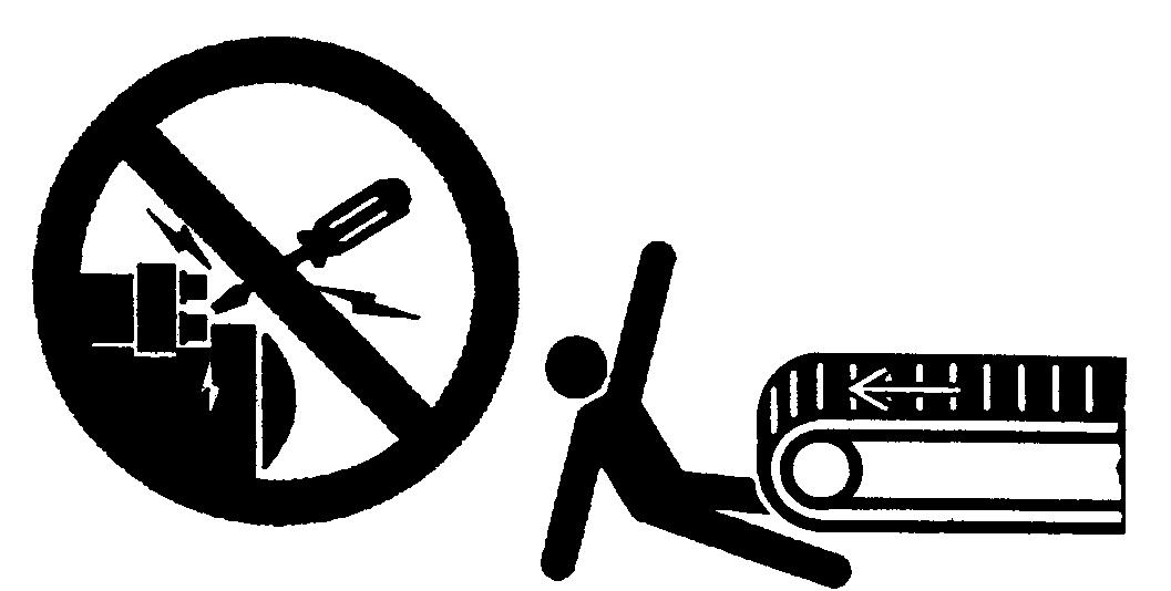
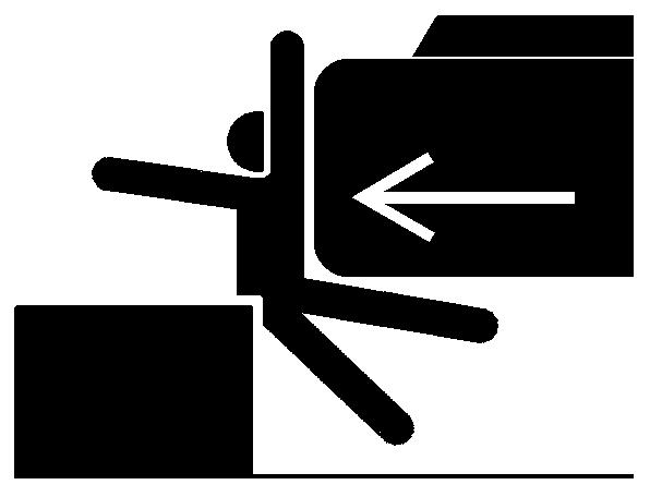
Pressure fluid escaping from a very small hole can be almost invisible and still have sufficient force to penetrate the skin.
Always check any suspected pressure leaks using a piece of cardboard or wood. Do not use hands. If injured by escaping fluid, obtain medical attention immediately or serious infection or reaction may develop.
Stop the engine and ensure pressure is relieved from all systems before removing side panels, housings, guards and covers. See the Operation and Maintenance Instruction Manual.
Always use gauges of adequate capacity for pressure testing. Refer to the Operation and Maintenance Instruction Manual or Repair Manual.
Always keep head, body, limbs, feet, hands, and fingers away from the bucket and attachments, when in the raised position.
Prior to any maintenance or repair work, install all supports necessary to this aim according to local and national safety regulations.
In case the attachment is to be operated for maintenance or repair purposes, do so exclusively while sitting in the driver’s seat.
Sound the horn before starting the machine or moving the attachment. Require that nobody remain near the machine. Raise the attachment slowly.
Do not use the machine to transport loose objects, unless proper securing devices are provided.
Never use gases other than nitrogen to charge the accumulators.
Refer to the Operation and Maintenance Instruction Manual.
This is your SAFETY ALERT SYMBOL.
When you see this symbol on your machine or in this Manual, be alert of the potential for personal injury. Follow recommended precautions and safe operating practices.
In this Manual you will find the following words: DANGER, WARNING, CAUTION, referring to different hazard risks.
These words are always accompanied by the safety alert symbol.
DANGER: indicates an imminent hazardous situation which, if not avoided, will result in death or serious injury.
WARNING: indicated a potential hazardous situation which, if not avoided, could result in death or serious injury.
CAUTION: indicates a potential hazardous situation which, if not avoided, may result in minor or moderate injury.
IMPORTANT: indicates a situation which, if not avoided, may cause damage to the machine.
NOTE: indicates an additional explanation for information purposes.
This Manual also contains this symbol accompanying instructions for correct behaviour as regards environmental protection.
Carefully read and follow all safety signs on the machine and all safety messages in this manual.
Safety signs should be installed maintained and replaced when necessary.
If a safety sign or this manual is damaged or missing, order a replacement from your dealer in the same way you order other replacement parts (be sure to state machine model and serial number when ordering).
Learn how to operate the machine and its controls correctly and safely.
Allow only trained, qualified, authorized personnel to operate the machine.
Keep your machine in proper working condition.
Unauthorized modifications to the machine may impair the function and/or safety and affect machine life.
The safety messages in this SAFETY PRECAUTIONS chapter are intended to illustrate basic safety procedures of hydraulic excavators. However it is impossible for these safety messages to cover every hazardous situation you may encounter.
If you have any questions, you should first consult your supervisor before operating and servicing the machine.
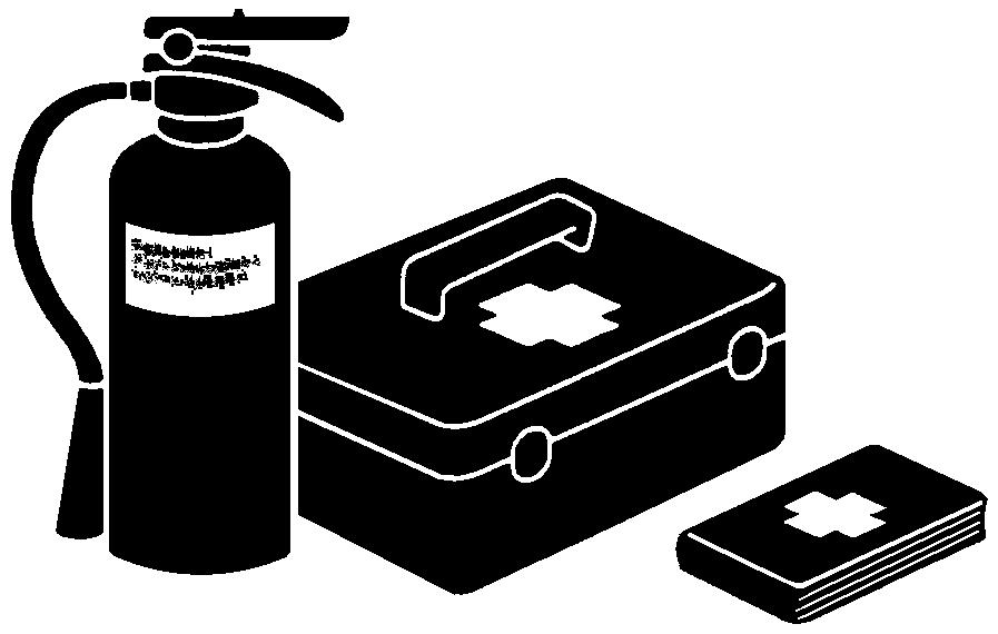
Be prepared if a fire starts or an accident occurs.
Keep the first-aid kit and fire extinguisher on hand. Thoroughly read and understand the label attached to the fire extinguisher to use it properly. Establish emergency priority procedures to cope with fires and accidents.
Keep emergency numbers for doctors, ambulance service, hospitals and fire department posted near the telephone.
Avoid wearing loose clothing, jewelry, or other items that can catch on control levers or other parts of the machine. Operating equipment safely requires the full attention of one operator. Do not wear radio or music headphones while operating machine.Wear close fitting clothing and safety equipment appropriate for the job.
Standard safety equipment includes:
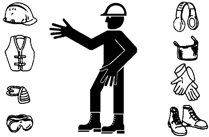
•A hard hat
• Safety shoes
• Safety glasses, goggles, or face shield
• Heavy gloves
• Hearing protection
• Reflective clothing
•Wet weather clothing
• Respirator or filter mask. Do not take chances. Wear whatever is needed for the job at hand.
Prolonged exposure to loud noise can cause impairment or loss of hearing.

Wear a suitable hearing protective device such as earmuffs or earplugs to protect against constant or uncomfortably loud noised.
Should the machine overturn, the operator may become injured and/or thrown from the cab. Not only, the operator may be crushed by the overturning machine resulting in serious injury or even death.
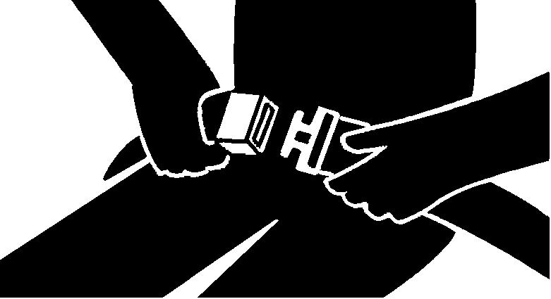
Prior to operating the machine, thoroughly examine belt webbing, buckle, and attaching hardware. If any item is damaged or worn, replace the seat belt or component before operating the machine. Be sure to remain seated with the seat belt securely fastened at all times when the machine is in operation to minimise injury hazard in case of accident. After a significant accident, replace the seat belts even though they do not look damaged.
Inspect the machine carefully every day or work-shift by an attentive visual inspection of machine outside prior to starting it to prevent damages and personal injuries.
In the walk-around inspection, be sure to cover all points detailed in the Chapter “MAINTENANCE”, paragraph “EXTERNAL VISUAL INSPECTION”.

Falling is one of the major causes of personal injury. When you get on and off the machine, always maintain a three-point contact with the steps and handrails and face the machine. Do not use any controls as hand-holds.
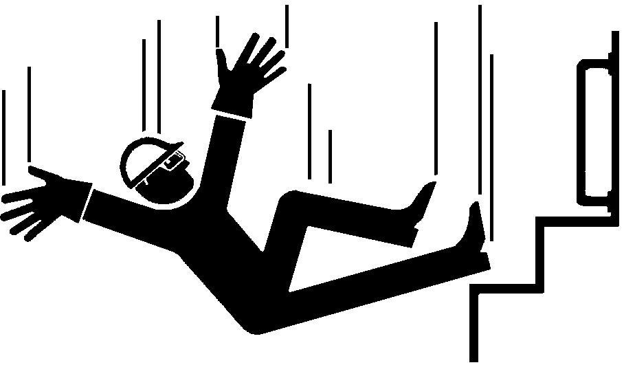
Never jump on or off the machine. Never mount or dismount a moving machine. Be careful of slippery conditions on platforms, steps, and handrails when leaving the machine.
A seat poorly adjusted for operator or work requirements may quickly fatigue the operator leading to improper operations.
• The seat should be adjusted whenever machine operator changes.
• The operator should be able to fully press the pedals and correctly move the control levers with his back resting against the seat back.
• If not, move the seat fore and aft, and check again.
To start the motor with an unsuitable procedure may cause sudden movement of the machine with possibility to cause serious injuries or mortal incidents
• start the engine only from the driver’s seat.
• NEVER start the engine while standing on a shoe or on the ground.
• Do not start the engine by short circuiting between starter motor terminals.
• Before starting the engine, ensure that all control levers are in the neutral position.
Riders on the machine are subject to injuries such as being struck by foreign objects and being thrown off the machine.
• Only machine operator is allowed on the machine. Keep riders off.
• Riders also obstruct the operator’s visibility, resulting in the machine being operated unsafely.
Serious injury or death can result if the machine or front attachments are not kept a safe distance from electric lines.
•When operating near an electric line, NEVER move any part of the machine or load closer than 3 m plus twice the line insulator length (L).
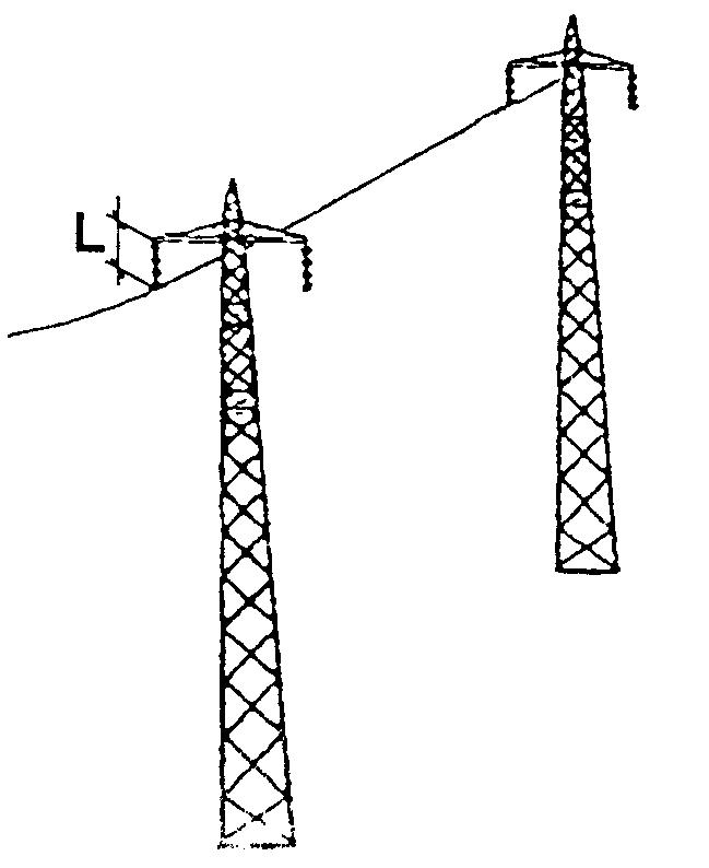
• Check and comply with any local regulations that may apply.
•Wet ground will expand the area that could cause any person on it to be affected by electric shock.
• Keep all bystanders or co-workers away from the site.
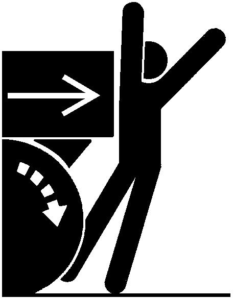
If someone stands near the machine when this is carrying out swinging or reverse-gear movement, the same can hit or run over this person causing heavy injuries or even death.
To avoid back-over and swing accidents: ALWAYS LOOK AROUND BEFORE YOU BACK UP AND SWING THE MACHINE. BE SURE THAT EVERYONE IS IN THE CLEAR.
Keep travel alarm in working condition (if equipped).
ALWAYS BE ALERT FOR BYSTANDERS MOVING INTO THE WORK AREA. USE HORN OR OTHER SIGNAL TO WARN BYSTANDERS BEFORE MOVING MACHINE.
A PERSON COULD STAND BEHIND THE MACHINE, IN A DEAD AREA, NOT VISIBLE FROM REARVIEW MIRRORS. BEFORE BACKING UP, MAKE SURE NOBODY IS STANDING IN THAT AREA.
Use a signal person when backing up if your view is obstructed. Always keep signal person in view.
No excavator or backhoe motions shall be made unless signals are clearly understood by both signalman and operator.
Learn the meaning of all flags, signs, and markings used on the job and confirm who has the responsibility for signaling.
Keep windows, mirrors, and lights clean and in good condition.
Dust, heavy rain, fog, etc., can reduce visibility. As visibility decreases, reduce speed and use proper lighting.
Read and understand all instruction for the operation given in this manual.
Accidental severing of underground cables or gas lines may cause an explosion and/or fire, possibly resulting in serious injury or death.
Before digging, check the location of cables, gas lines, and water lines. Keep the minimum distance required by law from cables, gas lines, and water lines. If a fiber optic cable should be accidentally severed, do not look into the end. Doing so may result in serious eye injury.
Contact local authorities and/or the utility companies directly (electric power, gas, telephone, water, sewers, telecommunications, etc.) to obtain information about underground utility lines.
Bystanders are in danger of being run over. Confirm the location of bystanders before moving, swinging, or operating the machine.
Always keep the travel alarm in good working condition. (if equipped). It warns people when the machine starts to move.
Use a signal person when moving, swinging, or operating the machine in congested areas. Coordinate hand signals before starting the machine.
Clear all persons from area of operation and machine movement.
Make sure worksite footing has sufficient strength to firmly support the machine.
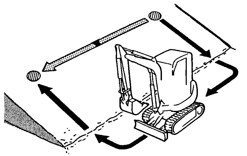
When working close to an excavation, operate the machine with che chassis frame positioned perpendicular to the cliff face, so that the machine can more easily evacuate if the cliff face collapses. Confirm that your machine is equipped with a F.O.P.S. (Falling Object Protective Structure) cab before working in areas where there is the possibility of falling stones or landslides.
When digging deeply, avoid hitting bottom of boom or bucket cylinder hoses against the ground. Use the bucket only for digging. To avoid accidents, do not use it as a jack hammer or wrecking ball.
• Cross-travelling on a slope can cause the machine skidding or overturning. When travelling up or down a slope, make sure the tyres are oriented in the slope direction.
• Turning on an incline may cause the machine to tip over. If turning on an incline is absolutely unavoidable, do so at a place where the slope is gentle and the surface is firm.
When operating on a slope, keep bucket low to ground and close to machine. Point chassis frame uphill to avoid tipping. To avoid tipping:
• Be extra careful before operating on a grade.
• Prepare machine operating area flat by grading.
• Keep the bucket low to the ground and close to the machine.
• Reduce machine operating speed to avoid tipping or slipping.
• Avoid changing direction when travelling on grades.
• Never attempt to travel across a grade steeper than 15 degrees.
• Reduce swing speed as necessary when swinging loads.

Be careful when working on frozen ground.
• Temperature increases will cause the ground to become soft and make ground travel unstable.
Before starting the machine, read carefully the "use and instructions manual" to get familiar with pedals and levers.
Before moving the machine, confirm which way to move travel pedals/levers for the corresponding direction you wish to go.
When traveling up or down a grade, keep the bucket in the direction of travel, approximately 30 to 40 cm (A) above the ground. If the machine begins to slip or becomes unstable, lower the bucket immediately.
In case of operation of the excavator under conditions where land slides with falling rocks or any conditions where there is a potential falling of objects of different nature that could endanger the operator, it is necessary to install a F.O.P.S. (Falling Object Protective Structure) to protect the cab.
If the front attachment or any other part of the machine hits against an overhead obstacle, such as a bridge, both the machine and the overhead obstacle will be damaged, and personal injury may results as well.
Take care to avoid hitting overhead obstacles with the boom or arm.
Death or serious injury may result if you attempt to get on or off a moving machine.
To avoid roll-aways:
• Select level ground when possible to park machine.
• Do not park the machine on a grade.
• Lower the bucket and/or other work tools to the ground. Thrust the bucket teeth into the ground if you must park on a grade.
• Turn the auto-idle switch off.
• Run the engine at slow idle speed without load for 5 minutes to cool down the engine.
• Stop the engine and remove the key from the key switch.
• Pull the safety lever (pilot control shut-off lever) to LOCK position.
• Block both tracks.
• Position the machine to prevent overturning.
• Park a reasonable distance from other machines.
Before working on the machine:
• Park machine on a level surface.
• Lower bucket to the ground.
• Move turret swing lever to lock position.
• Run engine at slow idle speed without load for 5 minutes.
• Turn key switch to to stop engine. Remove key from switch.
• Pull pilot control shut-off lever to LOCK position.
• Allow engine to cool.
• Close windows, roof window, and cab door.
• Lock all access doors and compartments.
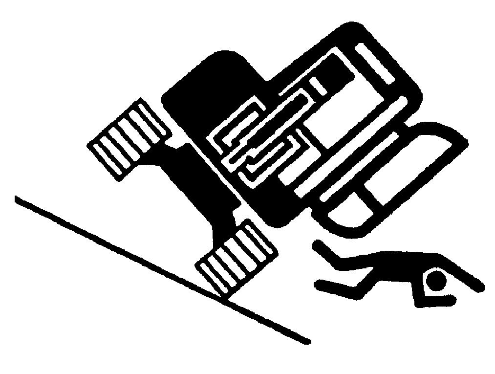
The edges could collapse or a land slide could occur causing serious injury or death.
For jobs involving several machines, provide signals commonly known by all personnel involved.

Also, appoint a signal person to co-ordinate the job site.
Make sure that all personnel obey the signal person’s directions.
• Instinctive travel pedal operation may result in serious injury and even death.
• Before driving the machine, be aware of the undercarriage position relative to the operator’s seat. If swinging/steering axle is located behind towards the counterweight, the machine will move reverse when control pedal is moved forwards.
A person may be hit severely by the swinging front attachment or counterweight and/or may be crushed against an other object, resulting in serious injury or death.
Keep all persons clear from the area of operation and machine movement.
Before operating the machine, set up barriers to the sides and rear area of the bucket swing radius to prevent anyone from entering the work area.
Never lift, move, or swing bucket above anyone or a truck cab.
Serious injury or machine damage may result due to bucket load spill or due to collision with the bucket.
Suggest:
If the above button click is invalid.
Please download this document first, and then click the above link to download the complete manual.
Thank you so much for reading

Never undercut or the footing might collapse. Before starting to work, make sure of the excavator control direction.
If the footing starts to collapse and if sufficient retreat is not possible, do not panic.
Often, the machine can be secured by lowering the front attachment.
The danger of tipping is present when loading/ unloading the machine onto/from a truck or trailer bed.
• Be sure to observe local regulations when transporting the machine on public roads.
• Provide an appropriate truck or trailer for transporting the machine.
Take the following precautions when loading/ unloading the machine:
• Select firm level ground.
• Be sure to use a loading dock or ramp.
• Be sure to have a signal person when loading/ unloading the machine.
• Always turn the auto-idle (A/I) switch off when loading or unloading the machine, to avoid unexpected speed increase due to unintentional operation of a control lever.
• Always select the slow speed mode with the travel speed selector.
In the high speed mode, travel speed may automatically increase.
