Solution manual for mechanics of materials 8th edition gere goodno 1111577730 9781111577735

Page 1

Solution Manual for Mechanics of Materials 8th Edition Gere Goodno 1111577730 9781111577735 Full Link Download: Solution Manual: https://testbankpack.com/p/solution-manual-for-mechanics-ofmaterials-8th-edition-gere-goodno-1111577730-9781111577735/

2 Axially Loaded Members

Changes in Lengths of Axially Loaded Members

Problem 2.2-1 The L-shaped arm ABCD shown in the figure lies in a vertical plane and pivots about a horizontal pin at A. The arm has constant cross-sectional area and total weight W. A vertical spring of stiffness k supports the arm at point B.

(a) Obtain a formula for the elongation of the spring due to the weight of the arm.

(b) Repeat part (a) if the pin support at A is moved to D.

© 2013 Cengage Learning. All Rights Reserved. May not be scanned, copied or duplicated, or posted to a publicly accessible website, in whole or in part. b b
k A B C b b b 2 (a) D Solution 2.2-1 (a) SUM MOMENTS ABOUT A b k 2 b 2 ©MA 0 5 Wb + b 2 W(2 b)kd b 5 b 2 A B C 2 b 5 Wb + b 2 d b 2 W(2 b) 5 b 2 6 W b 2 D (b) (b) ©MD 0 kb kb d 2 b Wb 5 k 4 Wb 2 b Wb 5 b 2 4 W so d 5 5 kb 5 k b 2 117

118 CHAPTER 2 Axially Loaded Members

Problem 2.2-2 A steel cable with nominal diameter 25 mm (see Table 2-1) is used in a construction yard to lift a bridge section weighing 38 kN, as shown in the figure. The cable has an effective modulus of elasticity E 140 GPa.

(a) If the cable is 14 m long, how much will it stretch when the load is picked up?

(b) If the cable is rated for a maximum load of 70 kN, what is the factor of safety with respect to failure of the cable?

Solution 2.2-2 Bridge section lifted by a cable A 304 mm2 (from Table 2-1)

(a) STRETCH OF CABLE WL (38 kN)(14 m)

EA (140 GPa)(304 mm2) 12.5 mm ;

Problem 2.2-3 A steel wire and an aluminum alloy wire have equal lengths and support equal loads P (see figure). The moduli of elasticity for the steel and aluminum alloy are Es 30,000 ksi and Ea 11,000 ksi, respectively

(a) If the wires have the same diameters, what is the ratio of the elongation of the aluminum alloy wire to the elongation of the steel wire?

(b) If the wires stretch the same amount, what is the ratio of the diameter of the aluminum alloy wire to the diameter of the steel wire?

(c) If the wires have the same diameters and same load P, what is the ratio of the initial length of the aluminum alloy wire to that of the steel wire if the aluminum alloy wire stretches 1.5 times that of the steel wire?

(d) If the wires have the same diameters, same initial length, and same load P, what is the material of the upper wire if it elongates 1.7 times that of the steel wire?

© 2013 Cengage Learning. All Rights Reserved. May not be scanned, copied or duplicated, or posted to a publicly accessible website, in whole or in part.
W
(b) FACTOR OF SAFETY PULT 406 kN (from Table 2-1) Pmax 70 kN E 140 GPa L 14 m n PULT Pmax 406 kN 70 kN 5.8 ;
38 kN
d
Steel
P P
wire Aluminum alloy wire

SECTION 2.2 Changes in Lengths of Axially Loaded Members 119

(c) SAME DIAMETER, SAME LOAD, FIND RATIO OF LENGTH OF ALUMINUM TO STEEL WIRE IF ELONGATION OF ALUMINUM IS 1.5 TIMES THAT OF STEEL WIRE

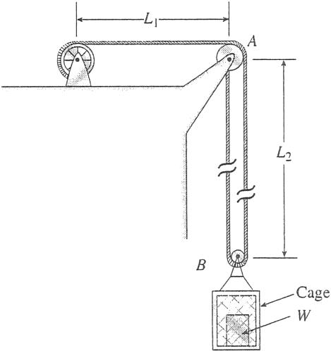
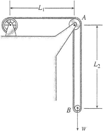
Problem 2.2-4 By what distance h does the cage shown in the figure move downward when the weight W is placed inside it?

Consider only the effects of the stretching of the cable, which has axial rigidity EA 10,700 kN. The pulley at A has diameter dA 300 mm and the pulley at B has diameter dB 150 mm. Also, the distance L1 4.6 m, the distance L2 10.5 m, and the weight W 22 kN. (Note: When calculating the length of the cable, include the parts of the cable that go around the pulleys at A and B.)

© 2013 Cengage Learning. All Rights Reserved. May not be scanned, copied or duplicated, or posted to a publicly accessible website, in whole or in part.
Solution
da (a) ds PL Ea A PL a Es A b : Es Ea Es 30,000 ksi Ea 11,000 ksi Es 2.727 Ea 30 2.727 11 PL PL Aa Es da Es (b) da ds so Ea Aa so Es As As and Ea ds CEa 1.651
2.2-3
PLa da Ea A ds PLs a Es A b PLa Ea A PLs a Es A b 1.5 La Ea 1.5 Ls Es 0.55 (d) S
LENGTH
LOAD
WIRE 1 ELONGATION 1.7 TIMES THE STEEL
WIRE 1 MATERIAL? PL d1 E1 A ds PL a Es A b PL E1 A PL a Es A b 1.7 E1 Es 17,647ksi 1.7 cast iron or copper alloy (see App. I)
AME DIAMETER, SAME
, SAME
BUT
WIRE WHAT IS

120 CHAPTER 2 Axially Loaded Members

Solution 2.2-4 Cage supported by a cable

dA 300 mm

dB 150 mm

L1 4.6 m

L2 10.5 m

EA 10,700 kN

W 22 kN

LENGTH OF CABLE 1 1

L L1 + 2L2 + 4 1pdA2 + 2 (pdB) 4,600 mm + 21,000 mm + 236 mm + 236 mm 26,072 mm

ELONGATION OF CABLE

TL (11 kN)(26,072 mm)

d EA (10,700 kN) 26.8 mm

LOWERING OF THE CAGE

h distance the cage moves downward

TENSILE FORCE IN CABLE

W T 11 kN 2

1

h d 13.4 mm ; 2

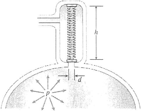
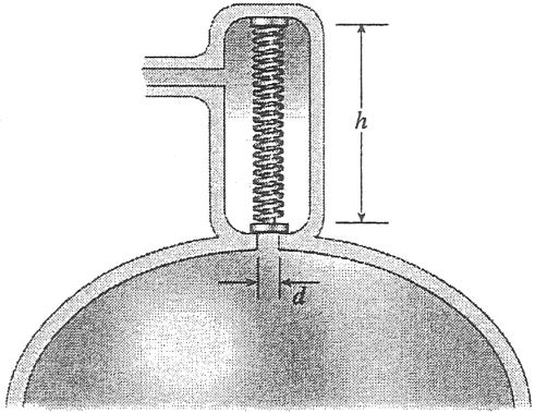
Problem 2.2-5 A safety valve on the top of a tank containing steam under pressure p has a discharge hole of diameter d (see figure). The valve is designed to release the steam when the pressure reaches the value pmax

If the natural length of the spring is L and its stiffness is k, what should be the dimension h of the valve? (Express your result as a formula for h.)

© 2013 Cengage Learning. All Rights Reserved. May not be scanned, copied or duplicated, or posted to a publicly accessible website, in whole or in part.

SECTION 2.2 Changes in Lengths of Axially Loaded Members 121

Solution 2.2-5 Safety valve

pmax pressure when valve opens

L natural length of spring (L h)

k stiffness of spring

FORCE IN COMPRESSED SPRING

F k(L h) (From Eq. 2-1a)

PRESSURE FORCE ON SPRING

pd2

P pmaxa 4 b

EQUATE FORCES AND SOLVE FOR h: ppmaxd2

h height of valve (compressed length of the spring)

d diameter of discharge hole

p pressure in tank

F P k1L h2 4

ppmax d2 h L ; 4 k

Problem 2.2-6 The device shown in the figure consists of a prismatic rigid pointer ABC supported by a uniform translational spring of stiffness k 950 N/m. The spring is positioned at distance b 165 mm from the pinned end A of the pointer. The device is adjusted so that when there is no load P, the pointer reads zero on the angular scale.

(a) If the load P 11 N, at what distance x should the load be placed so that the pointer will read u 2.5° on the scale (see figure part a)?

(b) Repeat part (a) if a rotational spring kr kb2 is added at A (see figure part b).

(c) Let x 7b/8. What is Pmax (N) if u cannot exceed 2°? Include spring kr in your analysis.

(d) Now, if the weight of the pointer ABC is known to be Wp 3 N and the weight of the spring is Ws 2.75 N, what initial angular position (i.e., u in degrees) of the pointer will result in a zero reading on the angular scale once the pointer is released from rest? Assume P kr 0.

(e) If the pointer is rotated to a vertical position (see figure part c), find the required load P, applied at mid-height of the pointer, that will result in a pointer reading of u 2.5° on the scale. Consider the weight of the pointer Wp in your analysis.

© 2013 Cengage Learning. All Rights Reserved. May not be scanned, copied or duplicated, or posted to a publicly accessible website, in whole or in part.

122 CHAPTER 2 Axially Loaded Members

2.2-6

(a) If the load P 11 N, at what distance x should the load be

placed so that the pointer will read u

on the scale

(b) Repeat (a) if a rotational spring kr kb2 is added at A (see

Fig. b).

(c) Now if x 7b/8, what is Pmax (N) if

(d) Now, if the weight of the pointer ABC is known to be Wp 3 N and the weight of the spring is Ws 2.75 N, what initial angular position (i.e., u in degrees) of the pointer will result in a zero reading on the angular scale once the pointer is released from rest? Assume P kr 0.

to self weight of spring:

© 2013 Cengage Learning. All Rights Reserved. May not be scanned, copied or duplicated, or posted to a publicly accessible website, in whole or in part. s
Solution
NUMERICAL DATA k 950 N/m b 165 mm P 11N u 2.5 umax 2 Wp 3N Ws 2.75N
x P
2.5°
(see Fig. a)? Sum moments about A,
for x: ku b2 A B C 0 θ k x 102.6 mm P x 102.6 mm b b/2 (a)
then solve
x P
kr k b2 25864
Sum moments about A
A B C 0 kr k ku b2 + kr u x P 205 mm x 1.244 b x 205 mm 7 b b/2 (b)
N#mm
, then solve for x:
2 ? x b 144.375 mm 8 Sum moments about A
P: Pmax kumaxb2 + kr umax 7 b 12.51N Pmax 12.51N 8
u cannot exceed
, then solve for
Deflection at spring
Deflection at
due
3 Wp a 4 bb W dBp 2.368 mm dBk 1.447 mm kb 2 k dB dB dBp + dBk 3.816 mm uinit 1.325 b OR uinit arctan a dB b b 1.325 uinit 1.325
due to Wp:
B

SECTION 2.2 Changes in Lengths of Axially Loaded Members 123

(e) If the pointer is rotated to a vertical position (figure part c), find the required load P, applied at mid-height of the pointer that will result in a pointer reading of u 2.5° on the scale. Consider the weight of the pointer, Wp, in your analysis.

Problem 2.2-7 Two rigid bars are connected to each other by two linearly elastic springs. Before loads are applied, the lengths of the springs are such that the bars are parallel and the springs are without stress.

(a) Derive a formula for the displacement d4 at point 4 when the load P is applied at joint 3 and moment PL is applied at joint 1, as shown in the figure part a. (Assume that the bars rotate through very small angles under the action of the load P)

(b) Repeat part (a) if a rotational spring, kr kL2 , is now added at joint 6. What is the ratio of the deflection d4 in the figure part a to that in the figure part b?

© 2013 Cengage Learning. All Rights Reserved. May not be scanned, copied or duplicated, or posted to a publicly accessible website, in whole or in part. b 5 4 2 δ δ
k 950 N/m b 165 mm Wp 3N k r kb2 25.864N#m u 2.5 Sum moments about A to get P: 0 C b/2 k u P 3 b a 4 b ckr + k a 3 b b b Wp a 4 b d 20.388 N B P 20.4 N P Wp 3b/4 A kr (c)
PL 1 Rigid bar 2L/3 P 2 L/3 3 k 2k L PL 1 Rigid bar 2L/3 P 2 L/3 3 k 2k L kr = kL2 4 6 4 5 Rigid bar 4 5 Rigid bar 6 4 (a) (b)

124 CHAPTER 2 Axially Loaded Members

Solution 2.2-7

(a) Derive a formula for the displacement d4 at point 4 when the load P is applied at joint 3 and moment PL is applied at joint 1, as shown.

Cuthorizontallythroughbothsprings to create upperandlower FBD’s. Summoments aboutjoint1forupperFBD and also sum moments about joint 6 for lower FBD to get two equations of equilibrium; assume both springs are in tension. Note

Summing moments about joint 1 (upper FBD) and about joint 6 (lower FBD) then dividing through by k gives

^ deltas are positive downward

(b) Repeat part (a) if a rotational spring kr kL2 is now added at joint 6. What is the ratio of the deflection d4 in part (a) to that in (b)?

^ deltas are positive downward

in part (a) to that in (b):

© 2013 Cengage Learning. All Rights Reserved. May not be scanned, copied or duplicated, or posted to a publicly accessible website, in whole or in part. 3 4 4 4 4
2 d2 3 d3 and 3 d5 4 d
Force
ad4 3 2 d3b
2 k a 4 d4 d3b
that
4
in left spring: k
Force in right spring:
22 13 9 6 d3 2 P d3 22 9 13 1 6 2 P 17 P 2 k 17 8.5 2 26 P ± 26 9 17 ≤ a d b k P 0 Q 6 a d b ± 26 9 17≤ 6 k P 0 Q ± 26P ≤ 3 k 26 8.667 3 d4 3 k
Upper FBD sum moments about joint 1: 2 2L 3 22 Lk 13 Lk k ad4 3 d3b 3 + 2k a 4 d4 d3b L 2PL OR a 9 b d3 + d4 2 PL 6 Lower FBD sum moments about joint 6: 2 4L 3 k ad4 3 d3b 3 + 2k a 4 d4 d3b L kr u6 0 2 4L 3 2 d4 26 Lk 43 Lk ck ad4 3 d3b 3 + 2k a 4 d4 d3b L d + (kL ) P 4 L Q 3 0 OR a 9 b d3 + d4 0 12 Divide matrix equilibrium equations through by k to get the following displacement equations: 22 13 9 6 d3 2 P d3 22 9 13 1 6 2 P 43 P 15 k 43 2.867 15 ± 26 9 43 ≤ a d b k P 0 Q 6 a d b ± 26 9 43≤ 12 k P 0 Q ± 104 P ≤ 45 k 104 2.311 45 d4 104 P 45 k
26 3 15 15 Ratio of the deflection d4
104 45 Ratio 4
© 2013 Cengage Learning. All Rights Reserved. May not be scanned, copied or duplicated, or posted to a publicly accessible website, in whole or in part. 3.75 4

SECTION 2.2 Changes in Lengths of Axially Loaded Members 125

Problem 2.2-8 The three-bar truss ABC shown in figure part a has a span L 3 m and is constructed of steel pipes having cross-sectional area A 3900 mm 2 and modulus of elasticity E 200 GPa. Identical loads P act both vertically and horizontally at joint C, as shown.

(a) If P 475 kN, what is the horizontal displacement of joint B?

(b) What is the maximum permissible load value Pmax if the displacement of joint B is limited to 1.5 mm?

(c) Repeat parts (a) and (b) if the plane truss is replaced by a space truss (see figure part b).

Solution 2.2-8

NUMERICAL DATA

A 3900 mm 2 E 200 GPa P 475 kN L 3000 mm

dBmax 1.5 mm

(a) FIND HORIZONTAL DISPLACEMENT OF JOINT B

STATICS TO FIND SUPPORT REACTIONS AND THEN MEMBER FORCES:

gMA 0 By 1 L L a2 P 2 b

By P

gFH 0 Ax P

gFV 0 Ay P By Ay 0

ACV AY ACV 0 Force in AC 0

(a) METHOD OF JOINTS: AB AX

Force in AB is P (tension) so elongation of AB is the horizontal displacement of joint B dB FAB L dB EA PL dB 1.82692 mm dB

(b) FIND Pmax IF DISPLACEMENT OF JOINT B dBmax 1.5 mm

(c) REPEAT PARTS (a) AND (b) IF THE PLANE TRUSS IS REPLACED BY A SPACE TRUSS (SEE FIGURE PART b).

FIND MISSING DIMENSIONS a AND c: P 475 kN L 3 m

© 2013 Cengage Learning. All Rights Reserved. May not be scanned, copied or duplicated, or posted to a publicly accessible website, in whole or in part.
P
C P
A
45° 45° B
L
EA EA
1.827 mm
Pmax dBmax Pmax 390 kN L y
P P C
C L L/2 A z Az L/2 Ay L/2 Ax a B x c Bz By (b)
z

CHAPTER 2 Axially Loaded Members

SUM MOMENTS ABOUT A LINE THRU A WHICH IS PARALLEL TO THE y-AXIS

ABOUT THE z-AXIS

(6) FIND DISPLACEMENT ALONG x-AXIS AT JOINT B Find change in length of member AB then find its projection along x axis:

(7) FIND Pmax FOR SPACE TRUSS IF Bx MUST BE LIMITED TO 1.5 mm

Displacements are linearly related to the loads for this linear elastic small displacement problem, so reduce load variable

© 2013 Cengage Learning. All Rights Reserved. May not be scanned, copied or duplicated, or posted to a publicly accessible website, in whole or in part. a b Bx Bx L C 126
2 2 a L a CL 2 a 2 b 2.12132 m 0.707 a 2.12132 m L 12 2 c 2L2 + a 2 3.67423 m c L2 + a L b 12 3.67423 m c L 3 C2 3.67423 m
L Bz P a 671.751
SUM MOMENTS
L P a 2 b By 335.876 kN SO Ay P By 139.124 kN a
SUM MOMENTS ABOUT
L Ay L P 2 Cz L 2 196.751kN (4) SUM FORCES IN THE x- AND z-DIRECTIONS Ax P 475 kN Az Cz Bz 868.503 kN (5) U
a c Sum forces in x-direction at joint A: c FAB + Ax 0 FAB L 2 a Ax 823 kN Sum forces in y-direction at joint A: Sum forces in y-direction
B
L FAC + Ay 0 FAC 121 Ay2 196.8 kN 12 2 L 2 FBC + By 0 FBC 2 By 672 kN L
(1)
kN (2)
(3)
THE x-AXIS
SE METHOD OF JOINTS TO FIND MEMBER FORCES
at joint
:
FABc L dAB dAB 3.875 mm b arctan 54.736 d 6.713 mm d 6.71 mm EA a cos(b)
to 1.5 6.71254 475 106.145 kN Pmax 106.1 kN Repeat
vector operations a = 2.121 m L = 3 m P = 475 kN
P from 475 kN
space truss analysis using

SECTION 2.2 Changes in Lengths of Axially Loaded Members 127

Reactions obtained using vector operations agree with those based on scalar operations.

Problem 2.2-9 An aluminum wire having a diameter d 1/10 in. P

and length L 12 ft is subjected to a tensile load P (see figure). The aluminum has modulus of elasticity E 10,600 ksi

If the maximum permissible elongation of the wire is 1/8 in. and the allowable stress in tension is 10 ksi, what is the allowable load Pmax?

© 2013 Cengage Learning. All Rights Reserved. May not be scanned, copied or duplicated, or posted to a publicly accessible website, in whole or in part.
POSITION AND UNIT VECTORS: rAB a 0 P LQ eAB rAB rAB 0.577 0 P 0.816Q rAC • 0 L 2 μ eAC L 2 rAC rAC 0 0.707 P 0.707Q FIND MOMENT AT A: MA rAB * RB + rAC * RC 0 2.P 3.0 m RBy + 1.5 m RCz 712.5 kN#m MA rAB * RBy PRBz Q + rAC * P PRCz Q 2.1213 m RBZ 1425.0 kN#m P 2.1213 m RBy 1425.0 kN#m Q FIND MOMENTS ABOUT LINES OR AXES: MA eAB 1.732 m RBy + 1.7321 m RBy + 0.86603 m RCz + 752.15 kN#m 244.12 RCz 338.262 Cz 196.751kN 0.72169 MA eAC 1.5 m RBy + 1.5 m RBz So RBy RBz 0 MA 1 P0Q 0 2.1213 m RBz + 1425.0 kN#m So RBz 462.5 1.7678 261.625 Bz 671.75 kN MA 1 P0Q 2.1213 m RBy + 1425.0 kN#m So RBy RBz 261.625 By 335.876 kN gFy 0 Ay P By 139.124kN
d
L

128 CHAPTER 2 Axially Loaded Members

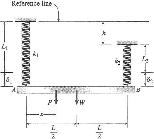
Problem 2.2-10 A uniform bar AB of weight W 25 N is supported by two springs, as shown in the figure. The spring on the left has stiffness

k1 300 N/m and natural length L1 250 mm The corresponding quantities for the spring on the right are k2 400 N/m and L2 200 mm The k1 b distance between the springs is L 350 mm, and the spring on the right is suspended from a support that is distance h 80 mm below the point

of support for the spring on the left Neglect the weight of the springs.

should a load P 18 N be placed in order to bring the bar to a

horizontal position?

(b) If P is now removed, what new value of k1 is required so that the weight W?

(c) If P is removed and k1 300 N/m, what distance b should spring k1 be moved to the right so that the bar (figure part a) will hang in a horizontal position under weight W?

(d) If the spring on the left is now replaced bytwo springs in series k3 (k1 300N/m, k3) with overall natural length L1 250 mm (see L figure part b), what value of k3 is required so that the bar will hang in a horizontal position under weight W?

only

© 2013 Cengage Learning. All Rights Reserved. May not be scanned, copied or duplicated, or posted to a publicly accessible website, in whole or in part. New position of k1 for part (c) only 1 1 k 2
Solution 2.2-9 1 d in. 10 1 L 12(12) in. E 10,600 (103) psi d a in. 8 2 s a 10 * (103) psi pd A 4 A 7.854 10 3 in.2 Maximum load based on elongation: EA EA 8.325 104 lb Pmax1 L da Pmax1 72.3 lb ; controls Maximum load based on stress: Pmax2 saA Pmax2 78.5 lb
h
L1 2
A
L2 B P Load P for
(a)
x L (a) h k1 k2 L L2 2 W A B L (b)
part

SECTION 2.2 Changes in Lengths of Axially Loaded Members 129

Solution 2.2-10

NUMERICAL DATA

W 25 N k1 0.300 N/mm L1 250 mm

k2 0.400 N/mm L2 200 mm

L 350 mm h 80 mm P 18 N

(a) LOCATION OF LOAD P TO BRING BAR TO HORIZONTAL POSITION

Use statics to get forces in both springs: 1 L

a MA 0 F2 L aW 2 + Pxb W x F2 2 + P L

a FV 0 F1 W + P F2

W x F1 2 + Pa1 L b

Use constraint equation to define horizontal position, then solve for location x:

L1 + F1 k1 L2 + h + F2 k2

Substitute expressions for F1 and F2 above into constraint equilibrium and solve for x:

© 2013 Cengage Learning. All Rights Reserved. May not be scanned, copied or duplicated, or posted to a publicly accessible website, in whole or in part.
x 2L1 L k1 k2 k2WL 2k2 P L + 2L2 L k1 k2 + 2 h L k1 k2 + k1W L 2P1k1 + k22 x
134.7 mm ;

130 CHAPTER 2 Axially Loaded Members

(b) NEXT REMOVE P AND FIND NEW VALUE OF SPRING CONSTANT k1 SO THAT BAR IS HORIZONTAL UNDER WEIGHT W

constraint equation as above but now P

[

(

+ h)]] W

(c) USE k1 0.300 N/mm BUT RELOCATE SPRING k1 (x b) SO THAT BAR ENDS UP

Constraint equation substitute above expressions for F1 and F2 and solve for b: IN HORIZONTAL POSITION UNDER WEIGHT W

(d) REPLACE SPRING k1 WITH SPRINGS IN SERIES:

74.1 mm ; New constraint equation; solve for k3:

/2, AND

IN HORIZONTAL POSITION

/2. FIND k3 SO

NOTE equivalent spring constant for series springs:

© 2013 Cengage Learning. All Rights Reserved. May not be scanned, copied or duplicated, or posted to a publicly accessible website, in whole or in part. b F1 F2 L/2 L/2 a b k 1 1 2 k k k
PART (C) CONTINUED STATICS Now, W F1 2 W F2 2 since P 0 a Mk1 0 F2 L w b 2 L b Same
0: a FV 0 L1 + W 2 1L2 + h2 1 W a 2 b 0 k2 F1 W F2 L Solve for k1: Wk2 F1 W Wa 2 bb L b k1 [2k
2 1 2 WL k1 0.204 N/mm ; F1 2( L b)
L
L
L/2 – b L1 + F1 F2 ( L2 + h) 0 1 k2
k1 0.300 N/mm k2 0.4 N/mm L1 250 mm L2 200 mm L 350 mm W L – b FBD b 2L1k1k2L + WLk2 2L2k1k2L 2hk1k2L Wk1L (2L1k1k2) 2L2k1k2 2hk1k2 2Wk1
Use the following data:
k1
N/mm,
,
HANGS
F1 L1 + 1 F1 + k3 F2 ( L2 + h) 0 2 STATICS W F1 2 W F2 2 W/2 L + W/2 ( L W/2 + h) 0 Wk1k2 1 k1 + k3 2 k2 k3 2L k k Wk2 + 2L2k1k2 + 2hk1k2 + Wk1 k3 0.638 N/mm ;
b
0.3
L1
k3
L1
THAT BAR
k1k3 k e 0.204 N/mm ; checks same as (b)
above
© 2013 Cengage Learning. All Rights Reserved. May not be scanned, copied or duplicated, or posted to a publicly accessible website, in whole or in part. k k e 1 + k3

SECTION 2.2 Changes in Lengths of Axially Loaded Members

Problem 2.2-11 A hollow, circular, cast-iron pipe (Ec 12,000 ksi) supports a brass rod (Eb 14,000 ksi) and weight W 2 kips, as shown The outside diameter of the pipe is dc 6 in.

(a) If the allowable compressive stress in the pipe is 5000 psi and the allowable shortening of the pipe is 0.02 in., what is the minimum required wall thickness tc,min? (Include the weights of the rod and steel cap in your calculations.)

(b) What is the elongation of the brass rod dr due to both load

W and its own weight?

(c) What is the minimum required clearance h?

Solution 2.2-11

The figure shows a section cut through the pipe, cap, and rod.

(a) MINIMUM REQUIRED WALL THICKNESS OF CAST IRON PIPE, tcmin

First check allowable stress then allowable shortening:

© 2013 Cengage Learning. All Rights Reserved. May not be scanned, copied or duplicated, or posted to a publicly accessible website, in whole or in part. 2 ) s
131
Nut &
dw
4 Steel
washer (
= 3 in.)
cap (ts = 1 in.)
Cast iron
(dc = 6 in., tc) Lr =3.5 ft
Brass rod ( dr = 1 in. h W
pipe
Lc = 4 ft
NUMERICAL DATA
Ec 12000 ksi Eb 14,000 ksi p 2 W 2 k dc 6 in. 1 dr 2 in. Wcap g s a 4 dcts b Wcap 8.018 10 3 k sa 5 ksi da 0.02 in. p 2
weights (see Table I-1):
b 3.009 * 10 4 k/in.3 Lc 48 in. Lr 42 in. gs 2.836 * 10 4 k/in.3 Wrod gb a 4 drLrb Wrod 2.482 10 3 k Wt W Wcap Wrod Wt 2.01 k W t ts 1 in. Amin a Amin 0.402 in.2 p 2 (d 2t )2] A pipe 4[d c c c
Unit
g

132 CHAPTER 2 Axially Loaded Members

(b) ELONGATION OF ROD DUE TO SELF WEIGHT AND ALSO WEIGHT

Now

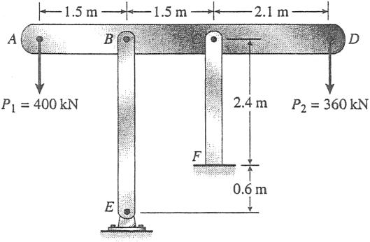
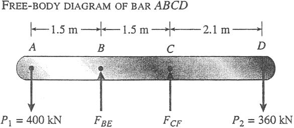
Problem 2.2-12 The horizontal rigid beam ABCD is supported by vertical bars BE and CF and is loaded by vertical forces

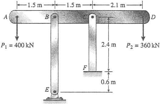
P1 400 kN and P2 360 kN acting at points A and D, respectively (see figure). Bars BE and CF are made of steel (E 200 GPa) and have cross-sectional areas ABE 11,100 mm2 and ACF 9,280 mm2 . The distances between various points on the bars are shown in the figure.

Determine the vertical displacements dA and dD of points A and D, respectively

© 2013 Cengage Learning. All Rights Reserved. May not be scanned, copied or duplicated, or posted to a publicly accessible website, in whole or in part. 2
2 d t b 0 WtLc b Apipe ptc(dc tc) t ( d t ) W t c c c ps a tc c c pEcda b 0.142 Let a 2 W t ps a a 0.128: tc dc 2 dc 4b 2 tc dctc a 0 2 tc 0.021 in. ; minimum based on da and sa t c d c 2 dc 4a 2 tc 0.021 in. ^ minimum based on sa controls
W Wrod
dr aW + 2 bLr p dr 0.031 in. ; dpipe WtLc E A Amin WtLc E d E b a 4 dr 2b c min c a
M
h Amin 0.447 in.2 larger than
based on sa above WtLc ptc(dc tc) E d hmin da dr hmin 0.051 in. ; c a
check allowable shortening requirement:
(c)
INIMUM CLEARANCE
value

SECTION 2.2 Changes in Lengths of Axially Loaded Members 133

Solution 2.2-12 Rigidbeam supported by vertical bars

SHORTENING OF BAR BE dBE FBELBE EABE

(296 kN)(3.0 m) (200 GPa)(11,100 mm2)

0.400 mm

SHORTENING OF BAR CF dCF FCFLCF EACF

(464 kN)(2.4 m) (200 GPa)(9,280 mm2)

ABE 11,100 mm 2

ACF 9,280 mm2

E 200 GPa

LBE 3.0 m

LCF 2.4 m

P1 400 kN; P2 360 kN

© 2013 Cengage Learning. All Rights Reserved. May not be scanned, copied or duplicated, or posted to a publicly accessible website, in whole or in part.
0.600 mm
dBE dA dCF dBE or dA 2dBE dCF dA 2(0.400 mm) 0.600 m 0.200 mm ; (Downward) 2.1 dD dCF 1.5(dCF dBE) 12 7 MB 0 or d D dCF dBE 5 5 12 (0.600 mm) 5 7 (0.400 mm) 5 (400 kN)(1.5 m) FCF(1.5 m) (360 kN)(3.6 m) 0 0.880 mm ; (Downward)
CF 464 kN MC 0 (400 kN)(3.0 m) FBE(1.5 m) (360 kN)(2.1 m) 0
BE 296 kN
DISPLACEMENT DIAGRAM
F
F

134 CHAPTER 2 Axially Loaded Members

Problem 2.2-13 Two pipe columns (AB, FC) are pin-connected to a rigid beam (BCD) as shown in the figure. Each pipe column has modulus E, but heights (L1 or L2) and outer diameters (d1 or d2) are different for each column. Assume the inner diameter of each column is 3⁄4 of outer diameter Uniformly distributed downward load q 2P/L is applied over a distance of 3L/4 along BC, and concentrated load P/4 is applied downward at D

(a) Derive a formula for the displacement dD at point D in terms of P and column flexibilities

BCD displaces downward to a horizontal posi-

tion under the load system in (a)

(c) If L1 2 L2, find the d1/d2 ratio so that beam BCD displaces downward to a horizontal position under the load system in (a)

(d) If d1 (9/8) d2 and L1/L2 1.5, at what horizontal distance x from B should load P/4 be placed so that beam BCD displaces downward to a horizontal position under the load system in part (a)?

© 2013 Cengage Learning. All Rights Reserved. May not be scanned, copied or duplicated, or posted to a publicly accessible website, in whole or in part. Pin 3L/4 x p 4 f p
f1 and f2 q = 2P/L Rigid beam Pin P/4
B C D
L/4 3L/4
1 L1, E d1 2 L2, E d2 A F Solution 2.2-13 (a) DISPLACEMENT dD Use FBD of beam BCD gMB 0 RC 1 L c a2 P 3 L b a 4 3 Lb a 8 Lb + P 4 aL + 3 Lb d P 6compression force in column CF P 3 P 3 P gFV 0 RB a2 L b a 4 Lb + 3 Pf1 RC 4 4 compression force in column BA Downward displacements at B and C: dB RB f1 3 dC RC f2 Pf2 4 Geometry: dD dB + (dC dB) P L + 4 L L Q 7 Pf2 4 9 Pf1 dD 16 7 Pf2 4 9 Pf1 16 P 16 128 f2 9 f12 (b) DISPLACEMENT TO HORIZONTAL POSITION, SO dC dB and 3 Pf1 4 f1 4 Pf2 or 2 3 L1 d1 2 EA1 L2 4 or L1 3 L2 4 A1 L1 3 a A2 b L2 4 4 3 ± ≤ d2 2 4 d1 2 3 d2 2 L1 4 L2 3 d1 2 a d2 b d1 9 with d2 8 EA2 L1 L2 4 9 2 27 3 a 8 b 16 4 L1 27 L2 16

SECTION 2.2 Changes in Lengths of Axially Loaded Members 135

© 2013 Cengage Learning. All Rights Reserved. May not be scanned, copied or duplicated, or posted to a publicly accessible website, in whole or in part. d 4 f L d 1
(c) IF L1 2 L2, FIND THE d1/d2 RATIO SO THAT BEAM BCD DISPLACES DOWNWARD TO A HORIZONTAL POSITION L1 d1 2 2 and dC dB from part (b). a b 2 d2 3 L1 4 a L2 d1 b so 2 3 (2) 1.225 A4 (d) IF d1 = (9/8) d2 AND L1/L2 = 1.5, AT WHAT HORIZONTAL DISTANCE X FROM B SHOULD LOAD P/4 AT D BE PLACED? d1 Given d2 9 and 8 L1 f1 1.5 or L2 f2 L1 A2 f1 L2 a A1 b f2 L1 d2 2 L2 a d1 b 3 8 2 32 2 a 9 b 27 Recompute column forces RB and RC but now with load P/4 positioned at distance x from B 9 LP Px 1 P 3 3 P 16 + 4 Use FBD of beam BCD: gMB 0 RC L ca2 L b a 4 Lb a 8 Lb + (x) 4 L 9 LP Px P 3 P 7 P 16 + 4 gFV 0 RB a2 L b a 4 Lb + RC 4 4 L Horizontal displaced position under load q and load P/4 so dC dB or RC f2 RB f1. 9 LP Px 9 LP Px 16 + 4 7 P 16 + 4 9 Lf2 19 Lf1 L19 f2 19f12 f2 P L Q P 4 L Q f1 solve, x f1 4 f1 + 4f2 41f1 + f22 19 9 L19 f2 19f12 x or x L ≥ f2 f ¥ 41f1 + f22 1 a + b 2 32 19 9 27 365 L 365 Now substitute f1/f2 ratio from above: x L ≥ 32 ¥ 4 a 27 + 1b 236 1.547 236

136 CHAPTER 2 Axially Loaded Members

Problem 2.2-14 A framework ABC consists of two rigid bars AB and B BC, each having a length b (see the first part of the figure part a). The b b bars have pin connections at A,B, and C and are joined by a spring of

stiffness k. The spring is attached at the midpoints of the bars. The framework has a pin support at A and a roller support a C, and the bars b b are at an angle a to the horizontal.

When a vertical load P is applied at joint B (see the second part of

the figure part a) the roller support C moves to the right, the spring is stretched, and the angle of the bars decreases from a to the angle u

(a) Determine the angle u and the increase d in the distance between points A and C Also find reactions at A and C (Use the following data: b 200 mm, k 3.2 kN/m, a 45 , and P 50 N.)

(b) Repeat part (a) if a translational spring k1 k/2 is added at C and a rotational spring kr kb2/2 is added at A (see figure part b).

(a) Initial position of structure

(a) - cont’d: displaced position of structure

Solution 2.2-14

(b) Displaced structure

Apply the laws of statics to the structure in its displaced position; also use FBD’s of the left and right bars alone (referred to as LHFB and RHFB below).

© 2013 Cengage Learning. All Rights Reserved. May not be scanned, copied or duplicated, or posted to a publicly accessible website, in whole or in part. A r C 2 C 2 2 2 2 1 P L 2
2
k
a a A C
P P B B u u A k k A C kr u u C
OVERALL FBD: gFH 0 HA k1d 0 so HA k1d gFV 0 RA + RC P gM 0 k (a u) P L2 + R L 0 R 2 1 L2 c L2 k r (a u)d d h L2 LHFB: gMB 0 HA h + k 2 a 2 b RA a 2 b + k r (a u) 0 2 d h RA 2 ck1 d h + k 2 a 2 b + kr (a u)d d h L2 2 d h RHFB: gMB 0 k 2 a 2 b k1 dh + RC 2 0 RC L ck 2 a 2 b + k1 d h d

SECTION 2.2 Changes in Lengths of Axially Loaded Members 137

© 2013 Cengage Learning. All Rights Reserved. May not be scanned, copied or duplicated, or posted to a publicly accessible website, in whole or in part. L C L 2 P 2 L2 L
C
expressions for L2, kr, k1, h and d 1 L2 L2 c 2 k r (a u)d 2 L2 d ck 2 h a 2 b + k1d h d OR 1 P L2 kr (a u)d c 2 2 b1cos1u2 cos1a22 b sin1u2 ck + k1[2b1cos1u2 cos1a22]1bsin1u22d d 0 L2 c 2 L2 2 2
SUBSTITUTE NUMERICAL VALUES, THEN SOLVE NUMERICALLY FOR ANGLE u AND DISTANCE INCREASE d b 200 mm k 3.2 kN/m a 45 P 50 N k1 0 kr 0 L2 2 b cos1u2 L1 2 b cos1a2 d L2 L1 d 2 b1cos1u2 cos1a22 h b sin1u2 1 P L2 kr 1a u2d c 1 2 b1cos1u2 cos1a22 b sin1u2 ck + k1[2b1cos1u2 cos1a22]1b sin1u22d d 0 L2 c 2 L2 2 2 Solving above equation numerically gives COMPUTE REACTIONS u 35.1 d 44.6 mm 2 d h 1 L2 RC 2 ck 2 a 2 b + k1 dh d 25 N RC L cP 2 kr 1a u2d 25 N 2 d h RA 2 ck1 d h + k 2 a 2 b + kr 1a u2d 25 N MA kr 1a u2 0 RA + RC 50 N 6 check RA 25 N RC 25 N (b) SUBSTITUTE NUMERICAL VALUES, THEN SOLVE NUMERICALLY FOR ANGLE u AND DISTANCE INCREASE d b 200 mm k 3.2 kN/m a 45 P 50 N k1 k k r 2 k b2 2 L2 2 bcos1u2 L1 2b cos1a2 d L2 L1 d 2 b1cos1u2 cos1a22 h b sin1u2 1 P L2 kr 1a u2d c 2 2 b1cos1u2 cos1a22 b sin1u2 ck + k1[2b1cos1u2 cos1a22]1bsin1u22d d 0 L2 c 2 L2 2 2 Solving above equation numerically gives COMPUTE REACTIONS u 43.3 d 8.19 mm 2 d h 1 L2 RC L ck 2 a 2 b + k1d h d 18.5 N R2 cP kr 1a u2d 18.5 N 2 d h RA 2 ck1 d h + k 2 a 2 b + k r 1a u2d 31.5 N MA k r 1a u2 1.882 N#m RA + RC 50 N 6 check RA 31.5 N RC 18.5 N MA 1.882 N#m
Equate the two expressions for R
then substitute
(a)

138 CHAPTER 2 Axially Loaded Members

Problem 2.2-15 Solve the preceding problem for the following data: b 8.0 in., k 16 1b/in., a 45 , and P 10 1b Solution 2.2-15

Apply the laws of statics to the structure in its displaced position; also use FBD’s of the left and right bars alone (referred to as LHFB and RHFB below)

Equate the two expressions above for RC then substitute expressions for

and

© 2013 Cengage Learning. All Rights Reserved. May not be scanned, copied or duplicated, or posted to a publicly accessible website, in whole or in part. 2 L C L 2 L P
OVERALL FBD gFH 0 HA k1d 0 so HA k1d gFV 0 RA + RC P L2 1 L2 gMA 0 kr (a u) P 2 + RC L2 0 RC L cP 2 kr (a u)d d h L2 LHFB gMB 0 HA h + k 2 a 2 b RA 2 + kr (a u) 0 2 d h RA 2 ck1 d h + k 2 a 2 b + kr (a u)d d h L2 2 d h RHFB gMB 0 k 2 a 2 b k1d h + RC 2 0 RC L ck 2 a 2 b + k1 dh d
L2,
,
1
1 L2 c L2 2 kr (a u)d 2 L2 d ck 2 h a 2 b + k1 dh d OR 1 P L2 kr (a u)d c 2 2 b1cos1u2 cos1a22 b sin1u2 ck + k1[2b1cos1u2 cos1a22]1bsin1u22d d 0 L2 c 2 L2 2 2 (a) SUBSTITUTE NUMERICAL VALUES
SOLVE NUMERICALLY FOR ANGLE u AND DISTANCE
b 8 in. k 16 lb/in. a 45 P 101b k1 0 kr 0 L2 2 bcos1u2 L1 2b cos1a2 d L2 L1 d 2b1cos1u2 cos1a22 h bsin1u2 1 P L2 kr 1a u2d c 2 2 b1cos1u2 cos1a22bsin1u2 ck + k1[2b1cos1u2 cos1a22]1bsin1u22d d 0 L2 c 2 L2 2 2
COMPUTE REACTIONS u 35.1 d 1.782 in. 2 d h 1 L2 RC 2 ck 2 a 2 b + k1 dh d 5 lb RC L cP 2 kr 1a u2d 5 lb 2 d h RA 2 ck1 d h + k 2 a 2 b + k11a u2d 5 lb MA kr1a u2 0
kr
k
, h,
d
, THEN
INCREASE d
Solving above equation numerically gives
© 2013 Cengage Learning. All Rights Reserved. May not be scanned, copied or duplicated, or posted to a publicly accessible website, in whole or in part. RA + RC 10 lb 6 check RA 5lb RC 5lb

Changes in Lengths under Nonuniform Conditions

Problem 2.3-1

(a) Calculate the elongation of a copper bar of solid circular cross section with tapered ends when it is stretched by axial loads of magnitude 3.0 k (see figure).

(The length of the end segments is 20 in. and the length of the prismatic middle segment is 50 in. Also, the diameters at cross sections A, B, C, and D are 0.5, 1.0, 1.0, and 0.5 in., respectively, and the modulus of

elasticity is 18,000 ksi. (Hint: Use the result of Example 2-4.)

(b) If the total elongation of the bar cannot exceed 0.025 in., what are the required diameters at B and C? Assume that diameters at A and D remain at 0.5 in.

© 2013 Cengage Learning. All Rights Reserved. May not be scanned, copied or duplicated, or posted to a publicly accessible website, in whole or in part. L 2 2 L A B p SECTION 2.3 Changes in Lengths under Nonuniform Conditions 139 (b) SUBSTITUTE NUMERICAL VALUES, THEN SOLVE NUMERICALLY FOR ANGLE u AND DISTANCE INCREASE d b 8 in. k 16 lb/in. a 45 P 101b k1 k kr 2 k b2 2 L2 2 bcos1u2 L1 2 b cos1a2 d L2 L1 d 2b 1cos1u2 cos1a22 h b sin1u2 1 P L2 kr 1a u2d c 2 2 b1cos1u2 cos1a22 b sin1u2 ck + k1[2b1cos1u2 cos1a22]1bsin1u22d d 0 L2 c 2 L2 2 2 Solving above equation numerically gives COMPUTE REACTIONS u 43.3 d 0.327 in. 2 d h 1 L2 RC 2 ck 2 a 2 b + k1 dh d 3.71lb RC L cP 2 kr 1a u2d 3.71 lb 2 d h RA 2 ck1 d h + k 2 a 2 b + kr 1a u2d 6.3 lb MA kr1a u2 1.252 ft#lb RA + RC 10.01lb 6 check RA 6.3lb RC 3.71lb MA 1.252 lb#ft
3.0 k A B 20 in. 50 in. C 20 in. D 3.0 k
Solution 2.3-1 NUMERICAL DATA P 3 k L1 20 in. L2 50 in. dA 0.5 in. dB 1 in. E 18000 ksi (a) TOTAL ELONGATION 4 PL1 PL2 d1 pE d d 0.00849 in. d E dB 2 4 0.01061 in. d 2 d1 + d2 0.0276 in. d 0.0276 in. (b) FIND NEW DIAMETERS AT B AND C IF TOTAL ELONGATION CANNOT EXCEED 0.025 in. 4 PL1 PL2
© 2013 Cengage Learning. All Rights Reserved. May not be scanned, copied or duplicated, or posted to a publicly accessible website, in whole or in part. p A B 2 a pE d d b + E d2 0.025 in. Solving for dB: dB 1.074 in. 4 B

140 CHAPTER 2 Axially Loaded Members

Problem 2.3-2 A long, rectangular copper bar under a tensile load P hangs from a pin that is supported by two steel posts (see figure). The copper bar has a length of 2.0 m, a cross-sectional area of 4800 mm2 , and a modulus of elasticity Ec 120 GPa. Each steel post has a height of 0.5 m, a cross-sectional area of 4500 mm2 , and a modulus of elasticity Es 200 GPa.

(a) Determine the downward displacement d of the lower end of the copper bar due to a load P 180 kN.

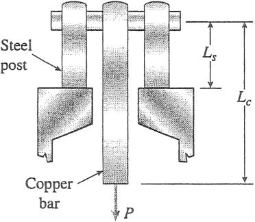
(b) What is the maximum permissible load Pmax if the displacement d is limited to 1.0 mm?

Solution 2.3-2 Copperbar with a tensile load

(a) DOWNWARD DISPLACEMENT d (P 180 kN)

PLc dc E A (180 kN)(2.0 m)

c c (120 GPa)(4800 mm2)

0.625 mm

(P/2)Ls (90 kN)(0.5 m)

ds

E As s (200 GPa)(4500 mm2)

mm

d dc + ds 0.625 mm + 0.050 mm

mm ;

(b) MAXIMUM LOAD Pmax (dmax 1.0 mm)

© 2013 Cengage Learning. All Rights Reserved. May not be scanned, copied or duplicated, or posted to a publicly accessible website, in whole or in part.
P
Steel post Copper bar
Lc 2.0 m 0.050
0.675
Ac 4800 mm2
Ec 120 GPa Ls 0.5 m Pmax P dmax d Pmax Pa dmax d b As 4500 mm2 Es 200 GPa Pmax (180 kN)a 1.0 mm 0.675 mm b 267 kN ;

Problem 2.3-3 An aluminum bar AD (see figure) has a cross-

sectional area of 0.40 in.2 and is loaded by forces P1 1700 lb, P2 1200 lb, and P3 1300 lb. The lengths of the segments of the bar are a 60 in., b 24 in., and c 36 in.

(a) Assuming that the modulus of elasticity E 10.4 106 psi, calculate the change in length of the bar Does the bar elongate or shorten?

(b) By what amount P should the load P3 be increased so that the bar does not change in length when the three loads are applied?

(c) If P3 remains at 1300 lb, what revised cross-sectional area for segment AB will result in no change of length when all three loads are applied?

© 2013 Cengage Learning. All Rights Reserved. May not be scanned, copied or duplicated, or posted to a publicly accessible website, in whole or in part.
P1 P2
A a B b C c 2 E A SECTION 2.3 Changes in Lengths under Nonuniform Conditions 141 P3 D
Solution 2.3-3 NUMERICAL DATA A 0.40 in.2 P1 1700 lb P2 1200 lb P3 1300 lb E 10.41106 psi a 60 in. b 24 in. c 36 in. (a) TOTAL ELONGATION 1 d EA C1P1 + P2 P32 a + 1P2 P32 b + 1 P32 cD 0.01125 in. d 0.01125 in. (elongation) (b) INCREASE P3 SO THAT BAR DOES NOT CHANGE LENGTH 1 EA C1P1 + P2 P32 a + 1P2 P32 b + 1 P32 cD 0 solve, P3 1690lb So new value of P3 is 1690 lb, an increase of 390 lb (c) NOW CHANGE CROSS-SECTIONAL AREA OF AB SO THAT BAR DOES NOT CHANGE LENGTH P3 1300 lb 1 a b c c1P1 + P2 P32 AB + 1P2 P32 A + 1 P32 A d 0 AAB Solving for AAB: AAB 0.78 in.2 1.951 A

142 CHAPTER 2 Axially Loaded Members

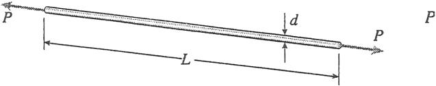
Problem 2.3-4 A rectangular bar of length L has a slot in the middle half of its length (see figure). The bar has width b, P thickness t, and modulus of elasticity E The slot has width b/4.

(a) Obtain a formula for the elongation d of the bar due to the axial loads P.

(b) Calculate the elongation of the bar if the material is high-strength steel, the axial stress in the middle region is 160 MPa, the length is 750 mm, and the modulus of elasticity is 210 GPa.

(c) If the total elongation of the bar is limited to

max 0.475mm, what is the maximum length of the slotted region? Assume that the axial stress in the middle region remains at 160 MPa.

© 2013 Cengage Learning. All Rights Reserved. May not be scanned, copied or duplicated, or posted to a publicly accessible website, in whole or in part. Q 3 ± a
b 4 b t L P 4 L 2 L 4 d
Solution 2.3-4 L L 2 P 4 2 7 LP 7 PL (a) d + E bt 3 ≤ bt 4 6 Ebt d 6 Ebt (b) NUMERICAL DATA E 210 GPa L 750 mm smid 160 MPa P P 3 so smid 3 bt 4 7 LP and 7 L smid bt 4 3 d 6 Ebt or d 6 E 4 smidb 0.5 mm d 0.5 mm P L Lslot Lslot P 1 4 (c) dmax E P b t + 3 bt 4 3 1 or dmax a bt b a E b aL Lslot + Lslot Lslotb or dmax a 4 smidb a E b aL + 4 Edmax 3 Lsmid 3 b Solving for Lslot with dmax 0.475mm Lslot Lslot smid 244 mm Lslot 244 mm 0.325 L

Problem 2.3-5 Solve the preceding problem if the axial stress in the middle region is 24,000 psi, the length is 30 in., and the

modulus of elasticity is 30 * 106 psi. In part (c), assume that

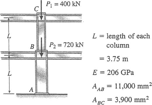
Problem 2.3-6 A two-story building has steel columns AB in the first floor and BC in the second floor, as shown in the figure The roof load P1 equals 400 kN and the second-floor load P2 equals 720 kN. Each column has length L 3.75 m The cross-sectional areas of the first- and second-floor columns are 11,000 mm 2 and 3,900 mm 2 , respectively

(a) Assuming that E 206 GPa, determine the total shortening dAC of the two columns due to the combined action of the loads P1 and P2

(b) How much additional load P0 can be placed at the top of the column (point C) if the total shortening dAC is not to exceed 4.0 mm?

© 2013 Cengage Learning. All Rights Reserved. May not be scanned, copied or duplicated, or posted to a publicly accessible website, in whole or in part.
C
kN L B L A
3.7 Q SECTION 2.3 Changes in Lengths
Nonuniform Conditions 143
P1 = 400 kN
P2 = 720
=
under
P
dmax 0.02 in. b 4 b t L P 4 L 2 L 4 Solution 2.3-5 (a) L 2 P 4 d ± + L 2 7 LP ≤ E bt 3 bt 4 6 Ebt (b) E 30,000 ksi L 30 in. smid 24 ksi P P 3 So smid 3 bt 4 7 LP and 7 L smid bt 4 3 d 6 Ebt or d 6 E a 4 smidb 0.021in. d 0.021in. P L Lslot Lslot P 1 4 (c) dmax E P bt + 3 bt 4 3 1 or dmax a bt b a E b aL Lslot + 3 Lslotb Lslot or dmax a 4 smidb a E b aL + 4 Edmax 3 Lsmid 3 b Solving for Lslot with dmax 0.02 in.: Lslot Lslot smid 10 in. Lslot 10 in. 0.333 L
= 3.75 m 5 m

144 CHAPTER 2 Axially Loaded Members

Solution 2.3-6 Steel columns in a building

(b) ADDITIONAL LOAD P0 AT POINT C

(dAC)max 4.0 mm

d0 additional shortening of the two columns due to the load P0

d0 (dAC)max dAC 4.0 mm 3.7206 mm 0.2794 mm P0L P0L P0L 1 1 Also, d0 AB

A EA EA + b

+ BC E a AAB BC

Solve for P0:

(a) SHORTENING dAC OF THE TWO COLUMNS Ed0 AAB ABC NiLi dAC g E A NABL EA NBCL + EA P0 L a AAB + ABC b

i i AB BC

(1120 kN)(3.75 m)

(206 GPa)(11,000 mm2)

(400 kN)(3.75 m) + (206 GPa)(3,900 mm2)

SUBSTITUTE NUMERICAL VALUES:

E 206 109 N/m2 d0 0.2794 10 3 m

L 3.75 m AAB 11,000 10 6 m 2

ABC 3,900 10 6 m 2

P0 44,200 N 44.2 kN ; 1.8535 mm + 1.8671 mm 3.7206 mm

dAC 3.72 mm ;

Problem 2.3-7 A steel bar 8.0 ft long has a circular cross section of diameter d1 0.75 in. over one-half of its length and diameter d2 0.5 in. over the other half (see figure part a). The modulus of elasticity E 30 * 106 psi.

(a) How much will the bar elongate under a tensile load P 5000 lb?

(b) If the same volume of material is made into a bar of constant diameter d and length 8.0 ft, what will be the elongation under the same load P?

(c) If the uniform axial centroidal load q 1250 lb/ft is applied to the left over segment 1 (see figure part b), find the ratio of the total elongation of the bar to that in parts (a) and (b).

d1 = 0.75 in.

d2 = 0.50 in. q = 1250 lb/ft

P

4.0 ft 4.0 ft

d1 = 0.75 in.

P = 5000 lb d2 = 0.50 in.

(a) 4.0 ft 4.0 ft

(b)

P = 5000 lb

© 2013 Cengage Learning. All Rights Reserved. May not be scanned, copied or duplicated, or posted to a publicly accessible website, in whole or in part.

Problem 2.3-8 A bar ABC of length L consists of two parts of equal lengths but different diameters. Segment AB has diameter d1 100 mm, and segment BC has diameter d2 60 mm. Both segments have length L/2 0.6 m.

A longitudinal hole of diameter d is drilled through segment AB for one-half of its length (distance L/4 0.3 m). The bar is made of plastic having modulus of elasticity E 4.0 GPa.

Compressive loads P 110 kN act at the ends of the bar

(a) If the shortening of the bar is limited to 8.0 mm, what is the maximum allowable diameter dmax of the hole?

(See figure part a.)

(b) Now, if dmax is instead set at d2/2, at what distance b from end C should load P be applied to limit the bar shortening to 8.0 mm? (See figure part b)

(c) Finally, if loads P are applied at the ends and P dmax d2/2, what is the permissible length x of the hole if shortening is to be limited to 8.0 mm? (See figure part c.)

© 2013 Cengage Learning. All Rights Reserved. May not be scanned, copied or duplicated, or posted to a publicly accessible website, in whole or in part. 2 4 max 2 p 2 d L SECTION 2.3 Changes in Lengths under Nonuniform Conditions 145 Solution 2.3-7 NUMERICAL DATA E 301106 psi P 5000 lb L 4 ft d1 0.75 in. d2 0.5 in. PL 1 1 + (a) da E P 4 d1 p 2 4 2 Q 0.0589 in. da 0.0589 in. p 2 p 2 3 Va p 2 2 (b) Va a 4 d1 + P12 L2 d2 b L 30.631 in. d p R 4 12 L2 0.637 in. A d 4 0.31907 in. db 0.0501 in. db 0.0501 in. EA (c) q 1250lb/ft L 4 ft dc q L2 + PL 0.0341 in. dc 0.58 dc 0.681 p 2 EA da db 2 E a 4 d1b
dmax A B d2 C P d1 P
L L 4 4 d = d2 2 A d1 L L 4 4 L 2 (a) B d2 P C b L 2 (b) d2 dmax = A B d2 C P d1 P x 2 x L 2 (c)

146 CHAPTER 2 Axially Loaded Members

2.3-8

(a) FIND dmax IF SHORTENING IS LIMITED TO da

(b) NOW, IF dmax IS INSTEAD SET AT d2 2, AT WHAT DISTANCE

C SHOULD LOAD P BE APPLIED TO LIMIT THE

© 2013 Cengage Learning. All Rights Reserved. May not be scanned, copied or duplicated, or posted to a publicly accessible website, in whole or in part. 2 2
NUMERICAL DATA d1 100 mm d2 60 mm L b c 2 A2c Eda P L a4A0 L + 4A1 bd d L 1200 mm E 4.0 GPa P 110 kN b 4.16 mm ; (c)
da 8.0 mm dmax d2 2, WHAT IS THE PERMISSIBLE LENGTH x
Solution
FINALLY IF LOADS P ARE APPLIED AT THE ENDS AND
OF
da 8.0 mm? p 2 A1 4 d1 P p 2 A2 4 d2 L L L 4 4 2 P d E J x A0 + L a 2 xb A1 L a 2 b + A2 K d E ≥ p + A1 + A2 ¥ Set d da and solve for x: 4 1d1 dmax 2 Ed a L 1 c A0A1a bd A0L P 2 A2 2 Set d to da, and solve for dmax: Eda pd1 2d2 2 2PLd2 2 2PLd1 2 dmax d19 Ed pd 2d 2 PLd 2 2PLd 2 x x 183.3 mm A1 A0 ; dmax 23.9 mm a 1 2 2 1 ;
THE HOLE IF SHORTENING IS TO BE LIMITED TO
b FROM
BAR SHORTENING TO da 8.0
p 2 d2 2 A0 4 c d1 a 2 b d p 2 A1 4 d1 p 2 A2 4 d2 P d E J L 4A0 L + 4A1 + L a 2 bb A2 K No
and solve for b:
END
mm?
axial force in segment at end of length b; set d da

Problem 2.3-9 A wood pile, driven into the earth, supports a

load P entirely by friction along its sides (see figure part a). The friction force f per unit length of pile is assumed to be uniformly distributed over the surface of the pile The pile has length L, cross-sectional area A, and modulus of elasticity E of P, L, E, and A.

(b) Draw a diagram showing how the compressive stress sc

(c) Repeat parts (a) and (b) if skin friction f varies linearly with depth (see figure part b).

© 2013 Cengage Learning. All Rights Reserved. May not be scanned, copied or duplicated, or posted to a publicly accessible website, in whole or in part. L = 0
147
SECTION 2.3 Changes in Lengths under Nonuniform Conditions
P P
Skin friction f f f (a) Skin friction f with depth f0 f L y (b) Solution 2.3-9 AFD LINEAR (a) N(y) fy d L(fy) L 0 EA dy L2 f 2 AE PL d 2 EA (b) s(y) N(y) A fy s(y) A fL P s(L) A A s(0) 0 So linear variation, zero at bottom, P/A at top (i.e., at ground surface) P N(L) f s(y) A y a L b 1 0.8 P A 1 0.8 σ (y) 0.6 0.4 Py σc AL σ (y) 0.6 0.4 0.2 Compressive stress in pile 0.2 0 0.5 1 0 y 0 0 0.5 1 y f(y) is constant f(y) is linear and and AFD is linear AFD quadratic

148 CHAPTER 2 Axially Loaded Members

Problem 2.3-10 Consider the copper tubes joined below using a “sweated” joint. Use the properties and dimensions given.

(a) Find the total elongation of segment 2-3-4 (d2-4) for an applied tensile force of P 5 kN. Use Ec 120 GPa.

(b) If the yield strength in shear of the tin-lead solder is ty 30 MPa and the tensile yield strength of the copper is sy 200 MPa, what is the maximum load Pmax that can be applied to the joint if the desired factor of safety in shear is FSt 2 and in tension is FSs 1.7?

(c) Find the value of L2 at which tube and solder capacities are equal.

Tin-lead solder in space between copper tubes; assume thickness of solder equal zero

© 2013 Cengage Learning. All Rights Reserved. May not be scanned, copied or duplicated, or posted to a publicly accessible website, in whole or in part.
(c) N(y) f(y)y y f0y(y 2) f0 N(y) L 0 f0 a1 L b d 2 N(L) 2 N(0) 0 f0L a 2 b d 3 EA 1 P 2 f0L d PL EA 2 a 3 b s(y) P y A c L a2 y f0 L b d s(0) 0 s(L) 2 P/A 2
Sweated joint Solder joints Segment number P P 1 2 3 4 5 L2 L3 L4 d0 = 22.2 mm t = 1.65 mm L3 = 40 mm d0 = 18.9 mm t = 1.25 mm L2 = L4 = 18 mm

SECTION 2.3 Changes in Lengths under Nonuniform Conditions 149

(b) MAXIMUM LOAD Pmax THAT CAN BE APPLIED TO THE

Problem 2.3-11 The nonprismatic cantilever circular bar shown has an internal cylindrical hole of diameter d/2 from 0 to x, so the net area of the cross section for Segment 1 is (3/4)A. Load R P is applied at x, and load P/2 is applied at x L Assume that E is constant.

(a) Find reaction force R1

(b) Find internal axial forces Ni in segments 1 and 2.

(c) Find x required to obtain axial displacement at joint 3 of d3 PL/EA

(d) In (c), what is the displacement at joint 2, d2?

(e) If P acts at x 2L/3 and P/2 at joint 3 is replaced by bP, find b so that d3 PL/EA

(f) Draw the axial force (AFD: N(x), 0 x L) and axial displacement (ADD: d(x), 0 x L) diagrams using results from (b) through (d) above.

CAPACITIES ARE EQUAL Set Pmax based on shear strength equal to Pmax based on tensile strength and solve for L2:

© 2013 Cengage Learning. All Rights Reserved. May not be scanned, copied or duplicated, or posted to a publicly accessible website, in whole or in part. Segment 1 Segment 2 o5 2 1 1 P
Solution 2.3-10 NUMERICAL DATA P 5 kN Ec 120 GPa
JOINT
stress: L2 18 mm L4 L2 L3 40 mm A1 p [ d2 d 4 o5 2 2t52 ] do3 22.2 mm t3 1.65 mm A1 69.311 mm smallest cross-sectional area do5 18.9 mm t5 1.25 mm controls normal stress Pmaxs saA1 Pmaxs 8.15 kN ; smaller than tY 30 MPa sY 200 MPa FSt 2 FSs 1.7 t Y
max based
so
check shear stress in solder joint: t a FSt ta 15 MPa Ash pdo5L2 Ash 1.069 103 mm 2 s Y Pmaxt taAsh Pmaxt 16.03 kN s a FSs sa 117.6 MPa (c) FIND THE VALUE OF L2 AT WHICH TUBE AND SOLDER (a) ELONGATION OF SEGMENT 2-3-4 A p [d2 (d 2t
2
2 4 o3 o5 5
First check normal
P
on shear below
normal stress controls Next
)
]
p 2 2 saA1 A3 4 [d o3 1d o3 2t32 ] L2 t pd L2 9.16 mm ; A2 175.835 mm2 A3 106.524 mm2 a1 o52 d24 P Ec a L2 + L4 A2 L3
A
b d
+
3
24 0.024 mm ;
3P 3 d 4 A d 2 2 x A P 2 3 L – x P
2 2 AFD 0 0 δ3 δ2
© 2013 Cengage Learning. All Rights Reserved. May not be scanned, copied or duplicated, or posted to a publicly accessible website, in whole or in part. ADD 0 0

150 CHAPTER 2 Axially Loaded Members

Solution 2.3-11

(b) DRAW FBD’S CUTTING THROUGH SEGMENT 1 AND AGAIN THROUGH SEGMENT 2

(c) FIND x REQUIRED TO OBTAIN AXIAL DISPLACEMENT AT JOINT 3 OF d3 PL/EA Add axial deformations of segments 1 and 2, then set

x ;

(d) WHAT IS THE DISPLACEMENT AT JOINT 2, d2?

(f) Draw AFD, ADD see plots for x 3

Problem 2.3-12 A prismatic bar AB of length L, cross-sectional area A, modulus of elasticity E, and weight W hangs vertically under its own weight (see figure).

(a) Derive a formula for the downward displacement C of point C, located at distance h from the lower end of the bar

(b) What is the elongation B of the entire bar?

(c) What is the ratio b of the elongation of the upper half of the bar to the elongation of the lower half of the bar? h

(d) If bar AB is a riser pipe hanging from a drill rig at sea, what is the total elongation of the pipe? Let L 1500 m, A 0.0157 m2 , E 210 GPa. See Appendix I for weight densities of steel and sea B water (See Problems 1.4-2 and 1.7-11 for additional figures).

© 2013 Cengage Learning. All Rights Reserved. May not be scanned, copied or duplicated, or posted to a publicly accessible website, in whole or in part. A C L
P F x 2L/3 AND P/2 AT JOINT 3 IS REPLACED BY bP,
STATICS a FH 0 R1 P 2 3 (e) I FIND b SO THAT d3 PL/EA R1 2 P ; N1 (1 b)P N2 2L bP x 3
(a)
substitute
above and
for b 3P N1 2 6 tension P N
tension 2L [(1 + b)P] 2L bP aL b
in axial deformation expression
solve
2 2 6
to
for
: 3 3 PL 3 + EA EA E A 4 1 8 + 11b PL PL N1x N2( L x) PL 9 EA EA + 3 EA EA E A 4 (8 11b) 9 1 3P P x 2 2 ( L x) PL b ; 11 + 3 EA EA E A 4 3 L L b 0.091 L
x
2 2 3
d3; solve
x
3
d2 N1
3 d2 a 2
3 3 E
E A 4 4 2
d2 3
P L
x
b
A
PL
EA

SECTION 2.3 Changes in Lengths under

Solution 2.3-12 Prismatic bar hanging vertically

151

© 2013 Cengage Learning. All Rights Reserved. May not be scanned, copied or duplicated, or posted to a publicly accessible website, in whole or in part. A C B y y h d d
Nonuniform Conditions
W Weight of bar (b) ELONGATION OF BAR (h 0) d (a) DOWNWARD DISPLACEMENT dC Consider an element at disL tance y from the lower end. WL dB ; 2EA (c) RATIO OF ELONGATIONS L N(y) Wy dd L N(y)dy EA Wydy EAL Elongation of upper half of bar ah 2 b: 3WL dupper 8EA Elongation of lower half of bar: L dC 1 dd 1 L Wydy W (L2 h2) dlower dB dupper WL 3WL WL h W h EAL 2 2 2EAL dupper 3/8 2EA 8EA 8EA dC 2EAL (L (d) NUMERICAL DATA h ) ; b dlower 3 ; 1/8 gs 77 kN/m3 gw 10 kN/m3 L 1500 m A 0.0157 m2 E 210 GPa In sea water: In air: WL W (gs gw) AL 1577.85kN d 2 EA 359 mm 2.393 * 10 4 L WL W (gs) AL 1813.35kN d 2 EA 412 mm 2.75 * 10 4 L

152 CHAPTER 2 Axially Loaded Members

Problem 2.3-13 A flat bar of rectangular cross section, length L, and constant thickness t is subjected to tension by b2 forces P (see figure). The width of the bar varies linearly

from b1 at the smaller end to b2 at the larger end. Assume that the angle of taper is small.

(a) Derive the following formula for the elongation of b1 the bar:

(b) Calculate the elongation, assuming L 5 ft, t 1.0 in., P 25 k, b1 4.0 in., b2 6.0 in., and E 30 106 psi.

Solution 2.3-13 Tapered bar (rectangular crosssection)

ELONGATION

BAR Substitute Eqs. (3) and (4) into Eq. (2):

© 2013 Cengage Learning. All Rights Reserved. May not be scanned, copied or duplicated, or posted to a publicly accessible website, in whole or in part. L L
t P
PL d Et(b2
ln b2 L b1 P
b1)
t thickness (constant) L0 + L b2 From Eq. (1): (Eq. 3) x b b1a 0 b b2 b1a L0 + L L0 b (Eq. 1) L0 b1 b1 x A(x) bt b1 ta b 0 Solve Eq. (3) for L0: L0 La b2 b1 b (Eq. 4) (a)
Pdx PL0 dx PL b2 d ln (Eq. 5) dd EA(x) Eb1 tx Et (b2 b1) b1 L0 L d dd PL0 L0 Ldx (b) SUBSTITUTE NUMERICAL VALUES: L 5 ft 60 in. t 10 in. L L0 Eb1 t L L0 x P 25 k b1 4.0 in. PL0 ln x L0 L PL0 ln L0 + L (Eq. 2) b2 6.0 in. E 30 106 psi Eb1 t L0 Eb1 t L0 From Eq. (5): d 0.010 in. ;
OF THE

Problem 2.3-14 A post AB supporting equipment in a laboratory

is tapered uniformly throughout its height H (see figure). The cross sections of the post are square, with dimensions b b at the top and 1.5b 1.5b at the base.

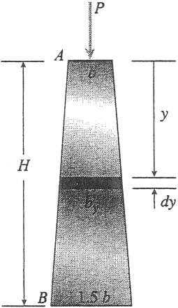
Derive a formula for the shortening d of the post due to the compressive load P acting at the top (Assume that the angle of taper is small and disregard the weight of the post itself.)

Solution 2.3-14 Tapered post

© 2013 Cengage Learning. All Rights Reserved. May not be scanned, copied or duplicated, or posted to a publicly accessible website, in whole or in part. A b 2 c d c d a 2 SECTION 2.3 Changes in Lengths under Nonuniform Conditions 153
P
A
b H B 1.5b B 1.5b
Ay cross-sectional area at distance y 1by 2 b2 H2(H + 0.5y)2 SHORTENING OF ELEMENT dy dd Pdy EAy b2 Pdy 2 E b1H + 0.5y2 H SHORTENING OF ENTIRE POST d dd L PH2 Eb2 L 0 H dy (H + 0.5y)2 dx 1 Square cross sections: b width at A 1.5b width at B From Appendix D: L(a + bx)2 b(a + bx) PH2 1 H d Eb2 (0.5)(H + 0.5y) 0 by width at distance y PH2 1 1 y b + (1.5b b) H + Eb2 (0.5)(1.5H ) 0.5H 2PH b H 1H + 0.5y2 ; 3Eb2

154 CHAPTER 2 Axially Loaded Members

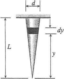
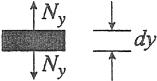
Problem 2.3-15 A long, slender bar in the shape of a right circular cone d with length L and base diameter d hangs vertically under the action of its own weight (see figure). The weight of the cone is W and the modulus of elasticity of the material is E

Derive a formula for the increase d in the length of the bar due to its own weight. (Assume that the angle of taper of the cone is small.)

Solution 2.3-15 Conical bar hanging vertically

dy

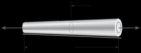
Problem 2.3-16 A uniformly tapered plastic tube AB of circular cross section and length L is shown in the figure The average diameters at the ends are dA and dB 2dA Assume E is constant Find the elongation d of the tube when it is subjected to loads P acting at the ends Use the following numerial data: dA 35 mm, L 300 mm, E 2.1 GPa, P 25 kN Consider two cases as follows:

(a) A hole of constant diameter dA is drilled from B toward A to

form a hollow section of length x L/2 (see figure part a)

(a)

© 2013 Cengage Learning. All Rights Reserved. May not be scanned, copied or duplicated, or posted to a publicly accessible website, in whole or in part. B
L
E
W weight of cone ELONGATION OF ELEMENT dy TERMINOLOGY dd Ny dy E A Wy dy E A L 4W 2 y dy y B pd EL Ny
ELONGATION OF CONICAL BAR Ay
AB cross-sectional area at
of
pd2 d dd L 4W L pd2 EL L 0 y dy 2WL ; pd2 E V volume of cone 4 1ABL 3 1 Ay y 3 Vy Vy volume of cone
Wy weight of cone below
Ay yW (W ) V AB L Ny Wy x P A P
LEMENT OF BAR
axial force acting on element
cross-sectional area at element dy
base
cone
below element dy
element dy
dA L dA dB

SECTION 2.3 Changes in Lengths under

(b) A hole of variable diameter d(x) is drilled from

B toward A to form a hollow section of length x L/2

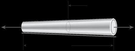
and constant thickness t (see figure part b) (Assume P

that t dA/20.)

© 2013 Cengage Learning. All Rights Reserved. May not be scanned, copied or duplicated, or posted to a publicly accessible website, in whole or in part. 2 4 c A A A p p
155
Nonuniform Conditions
B
A
P dA L d(x) t constant dB (b) Solution 2.3-16 (a) ELONGATION d
OF
DIAMETER HOLE d( ) dAa1 + L b A( ) p d( )2 4 p solid portion of length L x A( ) (d( )2 dA 2) 4 hollow portion of length x P d a 1 d b P d c L x 4 L d + 4 d d E L A( ) E L 0 pd( )2 LL x p1d( )2 dA 2 P L x d E 1 L 2 d + L c 1 d 2 2 J L 0 c 4 cdAa1 + L b d d L x 4 c cdAa1 + L b d dA dd K P L2 d E ( 2 x)pd 2 + L L 4 + pd 2 p 1 d 2 2 J A J J A L L x c 4 c cdAa1 + L b d dA d d KK K P d 4 E L2 ( 2 x)pdA 2 + a4 L pdA 2 2Lln(3) pdA 2 + 2L ln(L x) + ln(3L x) pdA 2 b d 1 5 if x L/2 P d E ± 4 L 3 pd2 2L ln(3) pd2 2L lna 2 Lb + lna 2 Lb pd2 ≤ Substitute numerical data: d 2.18 mm ;
x
FOR CASE
CONSTANT

Turn static files into dynamic content formats.

Create a flipbook
Issuu converts static files into: digital portfolios, online yearbooks, online catalogs, digital photo albums and more. Sign up and create your flipbook.