
PROBLEM 2.1
A nylon thread is subjected to a 8.5-N tension force. Knowing that E 3.3 GPa and that the length of the thread increases by 1.1%, determine (a) the diameter of the thread, (b) the stress in the thread.
PROPRIETARY MATERIAL. Copyright © 2015 McGraw-Hill Education. This is proprietary material solely for authorized instructor use. Not authorized for sale or distribution in any manner. This document may not be copied, scanned, duplicated, forwarded, distributed, or
on a website, in
PROPRIETARY MATERIAL. Copyright © 2015 McGraw-Hill Education. This is proprietary material solely for authorized instructor use. Not authorized for sale or distribution in any manner. This document may not be copied, scanned, duplicated, forwarded, distributed, or posted on a website, in whole or part.
or
PROBLEM 2.2
A 4.8-ft-long steel wire of 1 -in.-diameter is subjected to a 750-lb tensile load. Knowing that E = 29 × 106 psi, determine (a) the elongation of the wire, (b) the corresponding normal stress.
PROPRIETARY MATERIAL. Copyright © 2015 McGraw-Hill Education. This is proprietary material solely for authorized instructor use. Not authorized for sale or distribution in any manner. This document may not be copied, scanned, duplicated, forwarded,
on a website, in
PROPRIETARY MATERIAL. Copyright © 2015 McGraw-Hill Education. This is proprietary material solely for authorized instructor use. Not authorized for sale or distribution in any manner. This document may not be copied, scanned, duplicated, forwarded, distributed, or posted on a website, in whole or part.
or
PROBLEM 2.3
An 18-m-long steel wire of 5-mm diameter is to be used in the manufacture of a prestressed concrete beam It is observed that the wire stretches 45 mm when a tensile force P is applied. Knowing that determine (a) the magnitude of the force P, (b) the corresponding normal stress in the wire.
PROPRIETARY MATERIAL. Copyright © 2015 McGraw-Hill Education. This is proprietary material solely for authorized instructor use. Not authorized for sale or distribution in any manner. This document may not be copied, scanned, duplicated, forwarded, distributed, or
on a website, in
PROPRIETARY MATERIAL. Copyright © 2015 McGraw-Hill Education. This is proprietary material solely for authorized instructor use. Not authorized for sale or distribution in any manner. This document may not be copied, scanned, duplicated, forwarded, distributed, or posted on a website, in whole or part.
or
PROBLEM 2.4
Two gage marks are placed exactly 250 mm apart on a 12-mm-diameter aluminum rod with E = 73 GPa and an ultimate strength of 140 MPa. Knowing that the distance between the gage marks is 250.28 mm after a load is applied, determine (a) the stress in the rod, (b) the factor of safety.
PROPRIETARY MATERIAL. Copyright © 2015 McGraw-Hill Education. This is proprietary material solely for authorized instructor use. Not authorized for sale or distribution in any manner. This document may not be copied, scanned, duplicated, forwarded,
on a
PROPRIETARY MATERIAL. Copyright © 2015 McGraw-Hill Education. This is proprietary material solely for authorized instructor use. Not authorized for sale or distribution in any manner. This document may not be copied, scanned, duplicated, forwarded, distributed, or posted on a website, in whole or part.
or
PROBLEM 2.5
An aluminum pipe must not stretch more than 0.05 in. when it is subjected to a tensile load. Knowing that E 10.1 106 psi and that the maximum allowable normal stress is 14 ksi, determine (a) the maximum allowable length of the pipe, (b) the required area of the pipe if the tensile load is 127.5 kips.
PROPRIETARY MATERIAL. Copyright © 2015 McGraw-Hill Education. This is proprietary material solely for authorized instructor use. Not authorized for sale or distribution in any manner. This document may not be copied, scanned, duplicated, forwarded, distributed, or posted on a website, in
PROPRIETARY MATERIAL. Copyright © 2015 McGraw-Hill Education. This is proprietary material solely for authorized instructor use. Not authorized for sale or distribution in any manner. This document may not be copied, scanned, duplicated, forwarded, distributed, or posted on a website, in whole or part.
PROBLEM 2.6
A control rod made of yellow brass must not stretch more than 3 mm when the tension in the wire is 4 kN. Knowing that E = 105 GPa and that the maximum allowable normal stress is 180 MPa, determine (a) the smallest diameter rod that should be used, (b) the corresponding maximum length of the rod.
PROPRIETARY MATERIAL. Copyright © 2015 McGraw-Hill Education. This is proprietary material solely for authorized instructor use. Not authorized for sale or distribution in any manner. This document may not be copied, scanned, duplicated, forwarded,
PROPRIETARY MATERIAL. Copyright © 2015 McGraw-Hill Education. This is proprietary material solely for authorized instructor use. Not authorized for sale or distribution in any manner. This document may not be copied, scanned, duplicated, forwarded, distributed, or posted on a website, in whole or part.
or
PROBLEM 2.7
A steel control rod is 5.5 ft long and must not stretch more than 0.04 in when a 2-kip tensile load is applied to it. Knowing that E 29 106 psi, determine (a) the smallest diameter rod that should be used, (b) the corresponding normal stress caused by the load.
PROPRIETARY MATERIAL. Copyright © 2015 McGraw-Hill Education. This is proprietary material solely for authorized instructor use. Not authorized for sale or distribution in any manner. This document may not be copied, scanned, duplicated,
PROPRIETARY MATERIAL. Copyright © 2015 McGraw-Hill Education. This is proprietary material solely for authorized instructor use. Not authorized for sale or distribution in any manner. This document may not be copied, scanned, duplicated, forwarded, distributed, or posted on a website, in whole or part.
PROBLEM 2.8
A cast-iron tube is used to support a compressive load. Knowing that E 10 106 psi and that the maximum allowable change in length is 0.025%, determine (a) the maximum normal stress in the tube, (b) the minimum wall thickness for a load of 1600 lb if the outside diameter of the tube is 2.0 in.
PROPRIETARY MATERIAL. Copyright © 2015 McGraw-Hill Education. This is proprietary material solely for authorized instructor use. Not authorized for sale or distribution in any manner. This document may not be copied, scanned, duplicated, forwarded, distributed, or
on a website,
PROPRIETARY MATERIAL. Copyright © 2015 McGraw-Hill Education. This is proprietary material solely for authorized instructor use. Not authorized for sale or distribution in any manner. This document may not be copied, scanned, duplicated, forwarded, distributed, or posted on a website, in whole or part.
PROBLEM 2.9
A 4-m-long steel rod must not stretch more than 3 mm and the normal stress must not exceed 150 MPa when the rod is subjected to a 10-kN axial load. Knowing that the rod. E 200 GPa, determine the required diameter of
PROPRIETARY MATERIAL. Copyright © 2015 McGraw-Hill Education. This is proprietary material solely for authorized instructor use. Not authorized for sale or distribution in any manner. This document may not be copied, scanned, duplicated, forwarded,
on a website, in
PROPRIETARY MATERIAL. Copyright © 2015 McGraw-Hill Education. This is proprietary material solely for authorized instructor use. Not authorized for sale or distribution in any manner. This document may not be copied, scanned, duplicated, forwarded, distributed, or posted on a website, in whole or part.
PROBLEM 2.10
A nylon thread is to be subjected to a 10-N tension. Knowing that E 3.2 GPa, that the maximum allowable normal stress is 40 MPa, and that the length of the thread must not increase by more than 1%, determine the required diameter of the thread. SOLUTION
Stress criterion:
Elongation criterion:
The required diameter is the larger value:
PROPRIETARY MATERIAL. Copyright © 2015 McGraw-Hill Education. This is proprietary material solely for authorized instructor use. Not authorized for sale or distribution in any manner. This document may not be copied, scanned, duplicated, forwarded, distributed, or posted on a website, in
PROPRIETARY MATERIAL. Copyright © 2015 McGraw-Hill Education. This is proprietary material solely for authorized instructor use. Not authorized for sale or distribution in any manner. This document may not be copied, scanned, duplicated, forwarded, distributed, or posted on a website, in whole or part.
or
PROBLEM 2.11
A block of 10-in. length and 1.8 × 1.6-in. cross section is to support a centric compressive load P The material to be used is a bronze for which E 14 × 106 psi. Determine the largest load that can be applied, knowing that the normal stress must not exceed 18 ksi and that the decrease in length of the block should be at most 0.12% of its original length.
The smaller value for P resulting from the required deformation criteria governs.
PROPRIETARY MATERIAL. Copyright © 2015 McGraw-Hill Education. This is proprietary material solely for authorized instructor use. Not authorized for sale or distribution in any manner. This document may not be copied, scanned, duplicated, forwarded, distributed, or
on a website, in
PROPRIETARY MATERIAL. Copyright © 2015 McGraw-Hill Education. This is proprietary material solely for authorized instructor use. Not authorized for sale or distribution in any manner. This document may not be copied, scanned, duplicated, forwarded, distributed, or posted on a website, in whole or part.
or
PROBLEM 2.12
A square yellow-brass bar must not stretch more than 2.5 mm when it is subjected to a tensile load. Knowing that E 105 GPa and that the allowable tensile strength is 180 MPa, determine (a) the maximum allowable length of the bar, (b) the required dimensions of the cross section if the tensile load is 40 kN.
PROPRIETARY MATERIAL. Copyright © 2015 McGraw-Hill Education. This is proprietary material solely for authorized instructor use. Not authorized for sale or distribution in any manner. This document may not be copied, scanned, duplicated, forwarded, distributed, or posted on a website,
PROPRIETARY MATERIAL. Copyright © 2015 McGraw-Hill Education. This is proprietary material solely for authorized instructor use. Not authorized for sale or distribution in any manner. This document may not be copied, scanned, duplicated, forwarded, distributed, or posted on a website, in whole or part.
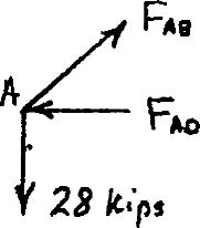
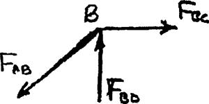
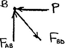
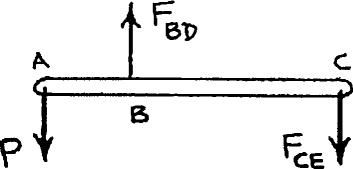
PROBLEM 2.13

Rod BD is made of steel (E 29 106 psi) and is used to brace the axially
compressed member ABC The maximum force that can be developed in member BD is 0.02P If the stress must not exceed 18 ksi and the maximumchange in length of BD must not exceed 0.001 times the length of ABC, determine the smallestdiameter rod that can be used for member BD.
PROBLEM 2.14
The 4-mm-diameter cable BC is made of a steel with E 200 GPa. Knowing
that the maximum stress in the cable must not exceed 190 MPa and that the elongation of the cable must not exceed 6 mm, find the maximum load P that can be applied as shown.

PROPRIETARY MATERIAL. Copyright © 2015 McGraw-Hill Education. This is proprietary material solely for authorized instructor use. Not authorized for sale or distribution in any manner. This document may not be copied, scanned, duplicated, forwarded,
PROPRIETARY MATERIAL. Copyright © 2015 McGraw-Hill Education. This is proprietary material solely for authorized instructor use. Not authorized for sale or distribution in any manner. This document may not be copied, scanned, duplicated, forwarded, distributed, or posted on a website,
2.15
A single axial load of magnitude P = 15 kips is applied at end C of the steel rod ABC Knowing that E = 30 × 106 psi, determine the diameter d of portion
for which the deflection of point C will be 0.05 in.
PROPRIETARY MATERIAL. Copyright © 2015 McGraw-Hill Education. This is proprietary material solely for authorized instructor use. Not authorized for sale or distribution in any manner. This document may not be copied, scanned, duplicated,
PROPRIETARY MATERIAL. Copyright © 2015 McGraw-Hill Education. This is proprietary material solely for authorized instructor use. Not authorized for sale or distribution in any manner. This document may not be copied, scanned, duplicated, forwarded, distributed, or posted
PROBLEM 2.16
A 250-mm-long aluminum tube (E 70 GPa) of 36-mm outer
36 mm 28 mm diameter and 28-mm inner diameter can be closed at both ends by means of single-threaded screw-on covers of 1.5-mm pitch. With one cover screwed on tight, a solid brass rod (E 105 GPa) of
25-mm diameter is placed inside the tube and the second cover is screwed on. Since the rod is slightly longer than the tube, it is observed that the cover must be forced against the rod by rotating it one-quarter of a turn before it can be tightly closed. Determine (a) the average normal stress in the tube and in the rod, (b) the deformations of the tube and of the rod.
PROPRIETARY MATERIAL. Copyright © 2015 McGraw-Hill Education. This is proprietary material solely for authorized instructor use. Not authorized for sale or distribution in any manner. This document may not be copied, scanned, duplicated, forwarded, distributed, or posted on
PROPRIETARY MATERIAL. Copyright © 2015 McGraw-Hill Education. This is proprietary material solely for authorized instructor use. Not authorized for sale or distribution in any manner. This document may not be copied, scanned, duplicated, forwarded, distributed, or posted on
PROPRIETARY MATERIAL. Copyright © 2015 McGraw-Hill Education. This is proprietary material solely for authorized instructor use. Not authorized for sale or distribution in any manner. This document may not be copied, scanned, duplicated, forwarded,
PROPRIETARY MATERIAL. Copyright © 2015 McGraw-Hill Education. This is proprietary material solely for authorized instructor use. Not authorized for sale or distribution in any manner. This document may not be copied,
PROBLEM 2.17
The specimen shown has been cut from a 1 -in.-thick sheet of vinyl (E = 0.45 × 10⁶ psi) and is subjected to a 350-lb tensile load. Determine (a) the total deformation of the
specimen, (b) the deformation of its central portion BC
PROPRIETARY MATERIAL. Copyright © 2015 McGraw-Hill Education. This is proprietary material solely for authorized instructor use. Not authorized for sale or distribution in any manner. This document may not be copied, scanned, duplicated, forwarded,
on a website, in
PROPRIETARY MATERIAL. Copyright © 2015 McGraw-Hill Education. This is proprietary material solely for authorized instructor use. Not authorized for sale or distribution in any manner. This document may not be copied, scanned, duplicated, forwarded, distributed, or posted on a website,
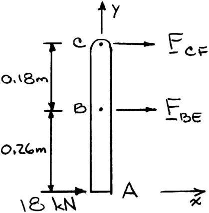
PROBLEM 2.18
The brass tube AB (E 105 GPa) has a cross-sectional area of 1 mm
140 mm 2 and is fitted with a plug at A The tube is attached at B to a rigid plate that is itself attached at C to the bottom of an aluminum cylinder (E 72 GPa) with a cross-sectional area of 250 mm 2 . The cylinder is then hung froma support at D In order to close the cylinder, the plug must move down through 1 mm. Determine the force P that must be applied to the cylinder.

PROBLEM 2.19
Both portions of the rod ABC are made of an aluminum for which E 70 GPa. Knowing that the magnitude of P is 4 kN, determine (a) the value of Q so that the deflection at A is zero, (b) the corresponding deflection of B

P PROBLEM 2.20

The rod ABC is made of an aluminum for which E 70 GPa Knowing that
determine the deflection of (
point
point B
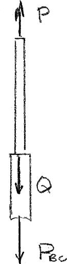
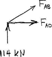
PROBLEM 2.21
For the steel truss (E 200 GPa) and loading shown, determine
the deformations of the members AB and AD, knowing that their cross-sectional areas are 2400 mm 2 and 1800 mm 2 , respectively

SOLUTION
Statics: Reactions are 114 kN upward at A and C Member BD is a zero force member. Use joint A as a free body

PROPRIETARY MATERIAL. Copyright © 2015 McGraw-Hill Education. This is proprietary material solely for authorized instructor use. Not authorized for sale or distribution in any manner. This document may not be copied, scanned, duplicated, forwarded, distributed, or
PROPRIETARY MATERIAL. Copyright © 2015 McGraw-Hill Education. This is proprietary material solely for authorized instructor use. Not authorized for sale or distribution in any manner. This document may not be copied, scanned, duplicated, forwarded, distributed, or posted on a website,
PROBLEM 2.22
For the steel truss (E 29 106psi) and loading shown, determine the
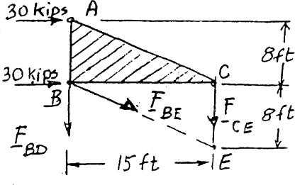
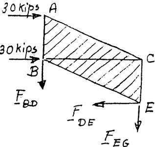
C deformations of the members BD and DE, knowing that their crosssectional areas are 2 in2 and 3 in2 , respectively.


PROPRIETARY MATERIAL. Copyright © 2015 McGraw-Hill Education. This is proprietary material solely for authorized instructor use. Not authorized for sale or distribution in any manner. This document may not be copied, scanned, duplicated,
PROPRIETARY MATERIAL. Copyright © 2015 McGraw-Hill Education. This is proprietary material solely for authorized instructor use. Not authorized for sale or distribution in any manner. This document may not be copied, scanned, duplicated, forwarded, distributed, or posted on a website,
PROBLEM 2.23
Members AB and BC are made of steel (E 29 106psi) with cross-


sectional areas of 0.80 in2 and 0.64 in2 , respectively. For the loading shown, determine the elongation of (a) member AB, (b) member BC.
PROPRIETARY MATERIAL. Copyright © 2015 McGraw-Hill Education. This is proprietary material solely for authorized instructor use. Not authorized for sale or distribution in any manner. This document may not be copied, scanned, duplicated, forwarded,
PROPRIETARY MATERIAL. Copyright © 2015 McGraw-Hill Education. This is proprietary material solely for authorized instructor use. Not authorized for sale or distribution in any manner. This document may not be copied, scanned, duplicated, forwarded, distributed, or posted on a website,
PROBLEM 2.24
The steel frame (E 200 GPa) shown has a diagonal brace BD with an area of 1920 mm 2 Determine the largest allowable load P if the change in length of member BD is not to exceed 1.6 mm.

PROPRIETARY MATERIAL. Copyright © 2015 McGraw-Hill Education. This is proprietary material solely for authorized instructor use. Not authorized for sale or distribution in any manner. This document may not be copied, scanned, duplicated, forwarded,
on a website, in
or
or
PROPRIETARY MATERIAL. Copyright © 2015 McGraw-Hill Education. This is proprietary material solely for authorized instructor use. Not authorized for sale or distribution in any manner. This document may not be copied, scanned, duplicated, forwarded, distributed, or posted on a website, in whole or part.
PROBLEM 2.25
Link BD is made of brass (E 105 GPa) and has a cross-sectional area of 240 mm 2 Link CE is made of aluminum (E 72 GPa) and has a cross-
sectional area of 300 mm 2 Knowing that they support rigid member ABC, determine the maximum force P that can be applied vertically at point A if the deflection of A is not to exceed 0.35 mm.
PROPRIETARY MATERIAL. Copyright © 2015 McGraw-Hill Education. This is proprietary material solely for authorized instructor use. Not authorized for sale or distribution in any manner. This document may not be copied, scanned, duplicated, forwarded, distributed, or posted on a website,
PROPRIETARY MATERIAL. Copyright © 2015 McGraw-Hill Education. This is proprietary material solely for authorized instructor use. Not authorized for sale or distribution in any manner. This document may not be copied, scanned, duplicated, forwarded, distributed, or posted on a website, in whole or part.
PROPRIETARY MATERIAL. Copyright © 2015 McGraw-Hill Education. This is proprietary material solely for authorized instructor use. Not authorized for sale or distribution in any manner. This document may not be copied, scanned, duplicated, forwarded, distributed, or posted on a website, in
PROPRIETARY MATERIAL. Copyright © 2015 McGraw-Hill Education. This is proprietary material solely for authorized instructor use. Not authorized for sale or distribution in any manner. This document may not be copied, scanned, duplicated, forwarded, distributed, or posted on a website, in whole or part.
PROBLEM 2.26
Members ABC and DEF are joined with steel links (E 200 GPa).
E Each of the links is made of a pair of 25 × 35-mm plates. Determine the change in length of (a) member BE, (b) member CF
PROPRIETARY MATERIAL. Copyright © 2015 McGraw-Hill Education. This is proprietary material solely for authorized instructor use. Not authorized for sale or distribution in any manner. This document may not be copied, scanned, duplicated, forwarded,
PROPRIETARY MATERIAL. Copyright © 2015 McGraw-Hill Education. This is proprietary material solely for authorized instructor use. Not authorized for sale or distribution in any manner. This document may not be copied, scanned, duplicated, forwarded, distributed, or posted on a website, in whole or part.
PROBLEM 2.27
Each of the links AB and CD is made of aluminum (E 10.9 106 psi) and has a cross-sectional area of 0.2 in2 Knowing that they support the rigid member BC, determine the deflection of point E
PROPRIETARY MATERIAL. Copyright © 2015 McGraw-Hill Education. This is proprietary material solely for authorized instructor use. Not authorized for sale or distribution in any manner. This document may not be copied, scanned, duplicated,
on a website, in
PROPRIETARY MATERIAL. Copyright © 2015 McGraw-Hill Education. This is proprietary material solely for authorized instructor use. Not authorized for sale or distribution in any manner. This document may not be copied, scanned, duplicated, forwarded, distributed, or posted on a website, in whole or part.
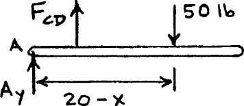
PROBLEM 2.28
The length of the 3 -in.-diameter steel wire CD has been adjusted so that with no load applied, a gap of 1 in exists between the end B of the rigid x beam ACB and a contact point E. Knowing that E 29 106 psi,
determine where a 50-lb block should be placed on the beam in order to cause contact between B and E
PROPRIETARY MATERIAL. Copyright © 2015 McGraw-Hill Education. This is proprietary material solely for authorized instructor use. Not authorized for sale or distribution in any manner. This document may not be copied, scanned, duplicated, forwarded,
PROPRIETARY MATERIAL. Copyright © 2015 McGraw-Hill Education. This is proprietary material solely for authorized instructor use. Not authorized for sale or distribution in any manner. This document may not be copied, scanned, duplicated, forwarded, distributed, or posted on a website, in whole or part.
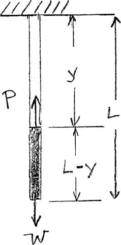
PROBLEM 2.29
A homogeneous cable of length L and uniform cross section is suspended from one end. (a) Denoting by the density (mass per unit volume) of the cable and by E its modulus of elasticity, determine the elongation of the cable due to its own weight. (b) Show that the same elongation would be obtained if the cable were horizontal and if a force equal to half of its weight were applied at each end.
SOLUTION
(a) For element at point identified by coordinate y,
(b) Total weight: W
PROPRIETARY MATERIAL. Copyright © 2015 McGraw-Hill Education. This is proprietary material solely for authorized instructor use. Not authorized for sale or distribution in any manner. This document may not be copied, scanned, duplicated, forwarded, distributed, or posted on a website, in
PROPRIETARY MATERIAL. Copyright © 2015 McGraw-Hill Education. This is proprietary material solely for authorized instructor use. Not authorized for sale or distribution in any manner. This document may not be copied, scanned, duplicated, forwarded, distributed, or posted on a website, in whole or part.
PROBLEM 2.30
A a A vertical load P is applied at the center A of the upper section of a homogeneous h frustum of a circular cone of height h, minimum radius a, and maximum radius b Denoting by E the modulus of elasticity of the material and neglecting the effect b of its weight, determine the deflection of point A

SOLUTION
Extend the slant sides of the cone to meet at a point O and place the origin of the coordinate system there.

PROPRIETARY MATERIAL. Copyright © 2015 McGraw-Hill Education. This is proprietary material solely for authorized instructor use. Not authorized for sale or distribution in any manner. This document may not be copied, scanned, duplicated, forwarded, distributed, or posted on a website, in whole or part.
PROPRIETARY MATERIAL. Copyright © 2015 McGraw-Hill Education. This is proprietary material solely for authorized instructor use. Not authorized for sale or distribution in any manner. This document may not be copied, scanned, duplicated, forwarded, distributed, or posted on a website, in whole or part.
PROPRIETARY MATERIAL. Copyright © 2015 McGraw-Hill Education. This is proprietary material solely for authorized instructor use. Not authorized for sale or distribution in any manner. This document may not be copied, scanned, duplicated, forwarded, distributed, or posted on a website, in whole or part.
PROPRIETARY MATERIAL. Copyright © 2015 McGraw-Hill Education. This is proprietary material solely for authorized instructor use. Not authorized for sale or distribution in any manner. This document may not be copied, scanned, duplicated, forwarded, distributed, or posted on a website, in whole or part.
PROBLEM 2.31
Denoting by the “engineering strain” in a tensile specimen, show that the true strain is
PROPRIETARY MATERIAL. Copyright © 2015 McGraw-Hill Education. This is proprietary material solely for authorized instructor use. Not authorized for sale or distribution in any manner. This document may not be copied, scanned, duplicated, forwarded, distributed, or
on a website, in whole or
PROPRIETARY MATERIAL. Copyright © 2015 McGraw-Hill Education. This is proprietary material solely for authorized instructor use. Not authorized for sale or distribution in any manner. This document may not be copied, scanned, duplicated, forwarded, distributed, or posted on a website, in whole or part.
PROBLEM 2.32
The volume of a tensile specimen is essentially constant while plastic deformation occurs. If the initial diameter of the specimen is d1, show that when the diameter is d, the true strain is t 2 ln(d1/d)
SOLUTION
If the volume is constant,
PROPRIETARY MATERIAL. Copyright © 2015 McGraw-Hill Education. This is proprietary material solely for authorized instructor use. Not authorized for sale or distribution in any manner. This document may not be copied, scanned, duplicated, forwarded, distributed, or posted on a website, in whole or part.
PROPRIETARY MATERIAL. Copyright © 2015 McGraw-Hill Education. This is proprietary material solely for authorized instructor use. Not authorized for sale or distribution in any manner. This document may not be copied, scanned, duplicated, forwarded, distributed, or posted on a website, in whole or part.
Aluminum plates (E = 70 GPa)

Brass core (E = 105 GPa) Rigid


PROBLEM 2.33


An axial centric force of magnitude P 450 kN is applied to the composite block shown bymeans of a rigid endplate. Knowing that h 10 mm, determine the normal stress in (a) the brass core, (b) the aluminum plates.
PROPRIETARY MATERIAL. Copyright © 2015 McGraw-Hill Education. This is proprietary material solely for authorized instructor use. Not authorized for sale or distribution in any manner. This document may not be copied, scanned, duplicated, forwarded, distributed, or posted on a website, in whole or
PROPRIETARY MATERIAL. Copyright © 2015 McGraw-Hill Education. This is proprietary material solely for authorized instructor use. Not authorized for sale or distribution in any manner. This document may not be copied, scanned, duplicated, forwarded, distributed, or posted on a website, in whole or part.
PROPRIETARY MATERIAL. Copyright © 2015 McGraw-Hill Education. This is proprietary material solely for authorized instructor use. Not authorized for sale or distribution in any manner. This document may not be copied, scanned, duplicated, forwarded,
on
PROPRIETARY MATERIAL. Copyright © 2015 McGraw-Hill Education. This is proprietary material solely for authorized instructor use. Not authorized for sale or distribution in any manner. This document may not be copied, scanned,
on a website,
Aluminum

PROBLEM 2.34
plate
For the composite block shown in Prob. 2.33, determine (a) the value of h if the portion of the load carried by the aluminum plates is half the portion of the load carried by the brass core, (b) the total load if the stress in the brass is 80 MPa.

PROBLEM 2.33. An axial centric force of magnitude
P 450 kN is applied to the composite block shown by means of a rigid end plate. Knowing that h 10 mm, determine the normal stress in (a) the brass core, (b) the aluminum plates.
PROPRIETARY MATERIAL. Copyright © 2015 McGraw-Hill Education. This is proprietary material solely for authorized instructor use. Not authorized for sale or distribution in any manner. This document may not be copied, scanned, duplicated, forwarded, distributed, or posted on a website, in whole or part.
PROPRIETARY MATERIAL. Copyright © 2015 McGraw-Hill Education. This is proprietary material solely for authorized instructor use. Not authorized for sale or distribution in any manner. This document may not be copied, scanned, duplicated, forwarded, distributed, or posted on a website, in whole or part. 130
PROPRIETARY MATERIAL. Copyright © 2015 McGraw-Hill Education. This is proprietary material solely for authorized instructor use. Not authorized for sale or distribution in any manner. This document may not be copied, scanned, duplicated, forwarded, distributed, or posted on a website, in whole or part. 131
PROPRIETARY MATERIAL. Copyright © 2015 McGraw-Hill Education. This is proprietary material solely for authorized instructor use. Not authorized for sale or distribution in any manner. This document may not be copied, scanned, duplicated, forwarded, distributed, or posted on a website, in whole or part. 131
P 1 ( A ) A 2 b b b b
P
(bAb)1 5
PROBLEM 2.34 (Continued)
P
(80 106 Pa)(0.04 m)(0.06 m)(1.5)
P
2.880 105 N
PROPRIETARY MATERIAL. Copyright © 2015 McGraw-Hill Education. This is proprietary material solely for authorized instructor use. Not authorized for sale or distribution in any manner. This document may not be copied, scanned, duplicated, forwarded, distributed, or posted on a website, in whole or part.
PROPRIETARY MATERIAL. Copyright © 2015 McGraw-Hill Education. This is proprietary material solely for authorized instructor use. Not authorized for sale or distribution in any manner. This document may not be copied, scanned, duplicated, forwarded, distributed, or posted on a website, in whole or part.
PROBLEM 2.35
The 4.5-ft concrete post is reinforced with six steel bars, each with a 11 -in. diameter. Knowing that Es 29 × 106 psi and Ec = 4.2 × 10⁶ psi, determine the normal stresses in the steel and in the concrete when a 350-kip axial centric force P is applied to the post.
Let
portion of axialforcecarried byconcrete


PROPRIETARY MATERIAL. Copyright © 2015 McGraw-Hill Education. This is proprietary material solely for authorized instructor use. Not authorized for sale or distribution in any manner. This document may not be copied, scanned, duplicated, forwarded,
on a website, in whole or

PROPRIETARY MATERIAL. Copyright © 2015 McGraw-Hill Education. This is proprietary material solely for authorized instructor use. Not authorized for sale or distribution in any manner. This document may not be copied, scanned, duplicated, forwarded, distributed, or posted on a website, in whole or part.

18 in.
PROBLEM 2.36
For the post of Prob 2.35, determine the maximum centric force that can be applied if the allowable normal stress is 20 ksi in the steel and 2.4 ksi in the concrete.
PROBLEM 2.35 The 4.5-ft concrete post is reinforced with six steel bars, each with 4.5 ft a 11 -in. diameter. Knowing that Es 29 × 106 psi and Ec 4.2 × 10⁶ psi, determine the normal stresses in the steel and in the concrete when a 350-kip axial centric force P is applied to the post.
SOLUTION
Allowable strain in each material:


Let P c = Portion of load carried by concrete.
Ps = Portion of load carried by 6 steel rods.
PROPRIETARY MATERIAL. Copyright © 2015 McGraw-Hill Education. This is proprietary material solely for authorized instructor use. Not authorized for sale or distribution in any manner. This document may not be copied, scanned, duplicated, forwarded, distributed, or posted on a website, in whole or part.
PROPRIETARY MATERIAL. Copyright © 2015 McGraw-Hill Education. This is proprietary material solely for authorized instructor use. Not authorized for sale or distribution in any manner. This document may not be copied, scanned, duplicated, forwarded, distributed, or posted on a website, in whole or part.
PROPRIETARY MATERIAL. Copyright © 2015 McGraw-Hill Education. This is proprietary material solely for authorized instructor use. Not authorized for sale or distribution in any manner. This document may not be copied, scanned, duplicated, forwarded,
on a website, in
PROPRIETARY MATERIAL. Copyright © 2015 McGraw-Hill Education. This is proprietary material solely for authorized instructor use. Not authorized for sale or distribution in any manner. This document may not be copied,
on a website, in whole or part.