CRITERIA FOR THE SELECTION OF CARBON FIBER COMPOSITE MATERIALS
FOR FIGHTER AIRCRAFT
P.J. Charitidis1, 2
1Center of Orthopaedic Research (C.O.RE) at Center for Interdisciplinary Research and Innovation-Aristotle University of Thessaloniki (CIRI-AUTH), Greece
2Democritus University of Thrace, Environmental Engineering School 67100, Xanthi, Greece
ABSTRACT
The main objective of the paper is to present the main criteria for the selection of carbon fiber composite materials for fighter aircraft. Nowadays, more than ever, customers for fighter aircraft demands a highly maneuverable, agile aircraft that is reliable and easy to maintain. Composite materials are, besides metal alloys, the most important materials for aerospace application. Application of carbon fiber thermosets as airframe materials offersa significant weight and cost reductions in manufacturing process. In the last decades, such materials overcome more than 15% and 50% of the structural weight of civil and military aircraft, respectively. Weak points in the basic materials, i.e. fiber (strain, stiffness) and resin (lowviscosity) are now well known and improvements led to a new generation of carbon fiber composites Several suppliers are offering in their chemical composition, mechanical properties and processing. This paper describes the selection criteria based on fighter aircraft components with respect to design and manufacturing requirements and presents a comparison of different carbon fiber composites.
KEYWORDS
fighter aircraft, carbon fiber, properties, manufacturing, cost
1. INTRODUCTION
Previous research has documented, that fighter aircraft usually drive new technologies because of their special requirements. Demand for the lightweight material from industry has grown significantly in the years. Nowadays, the use of composite materials overcomes more than 50% [1], while offer many advantages such as high strength and stiffness to weight ratios, excellent fatigue properties and corrosion resistance are concerned [2]. For instance, carbon fibers have the highest specific strength, stiffness and Young's modulus [3]. The density is 1.75 kg/dm3 with a single diameter of 5-15 µm. [4]. Generally, lightweight structures provide increased payload, improved agility, short take-off, long range missions and high maneuverable capabilities. Reviewing subsequent and more recent literature,composite materials were first introduced in military aircrafts in the 1960s and laterextended to the civil aircraft applications in the 1970s [5, 6] However, it took 30 years for the utilization of composites in the primary applications.
To the author’s knowledge, it has been demonstrated by the structural composite components that typical weight savings of 15-20% can be achieved compared to equivalent aluminum designs (integrated design and optimization). Therefore, in some cases, the application of components has led to significant increase in part cost. The increased applications of carbon fiber thermosets starting with secondary structures, control surfaces and later with wing and primary fuselage structures have proven that almost all structured aircraft parts can be built from these materials and that the expected benefits can be achieved. This experience justifies the increase utilized for the next generation of modern aircraft. In order to reduce cost and weight of the aircraft, thermoplastic materials were used, which are more expensive than metals because of their advanced properties. It is difficult to reduce the price of raw materials and therefore it is
Advances in Materials Science and Engineering: An International Journal (MSEJ), Vol. 5, No.2/3/4, December 2018
considered easier to lower the costs in manufacturing processes [2, 7]. There is a high development process towards new carbon fiber types with improved stiffness and strength. Carbon fibers are manufactured from rayon, polyacrylonitrile (PAN) and petroleum pitch. When it is manufactured from rayon and PAN, the starting point of the carbon fiber process is textile fibers. The fiber manufacture method may be solution or melt spinning [8].Furthermore, modern aircraft structures are accordingly built of thin layers of pre-impregnated fibers stacked to laminates. The fibers in the thin layers are usually uni-directional (UD) carbon fibers matrix or woven fabric pre-impregnated with a polymer resin. Both woven fabrics and UD matrices are used in the manufacturing industry of aircraft structures. Due to the opportunities for automation and costs, UD pre-preg materials are often chosen. Methods such as Automated tape lay (ATL) and Advanced Fiber Placement (AFP), were usually used in industries, produces high cost components. Several publications have appeared in recent years documented to such methods by many researchers [9-14]
The fiber volume content of UD prepreg materials use for commercial aircraft is in the range of 55 – 57 volume percent. When cured under heat and pressure, they form ultimate strong and lightweight composite parts [15]. For aero structure components, pre-preg technology seems to be relevant even in the future due to lack of reliable technologies [16]. This type of technology offers the highest mass specific stiffness and strength compared to other composite technologies. For instance, boron reinforced epoxy composite was used for the skins of the empennages of the U.S. F-14 and F-15 fighters [17, 18]. The percentage of structural weight of composites used in manufacturing was very small, 2% in the F-15 [18]. However, the percentage has grown considerably, through 19% in the F-18 up to 24% in the F-22 [18, 19]
Such materials are also used in Eurofighter Typhoon. The wing skins, forward fuselage, flaperons and rudder all make use of composites. As shown in Fig. 1, toughened epoxy skins constitute about 75% of the exterior surface [20]. On the other hand, the use of composite materials is not privilege of fighter aircraft. The first significant use of composite material in a commercial aircraft was by Airbus in 1983 in the rudder of the A300 and A310, and then in 1985 in the vertical tail [21].
Composites are widespread interest for transportation applications due to the high specific stiffness and strength, while the manufacturing process offers a lighter product. As an effect of the lower weight, the fuel consumption can be reduced,as well as, the emissions [22]. It has been found, that an extra kilogram in an airliner requires 130 liters of fuel per year. In general terms, spend money to increase range or payload, rather to spend money to fuel. The increased application of carbon fiber thermosets starting with secondary structures, control surfaces and later with wing and primary fuselage structures has proven that almost all structural aircraft parts can be built from these materials and that the expected benefits can be achieved.This experience justifies the increase of composite utilization for the next generation of modern aircraft (fig. 1).
It can be expected that carbon fiber composites will be used to an extent that almost all the wetted area and about 40% of the structural weight will be made from carbon fiber composite.The constant demand for improved performance in the development of new fighter aircraft requires substantial weight reductions in the load carrying structure. Besides improvements in the design techniques (e.g. integrated design, optimization), carbon fiber composites together with more efficient construction methods offer a significant weight saving potential. This study describes the criteria of the selection of carbon fibers composites for fighter aircrafts, in order to select the most suitable with respect to weight, strength and cost, a thorough knowledge of the requirements.
2. AIRCRAFT STRUCTURES: STRESSING CRITERIA
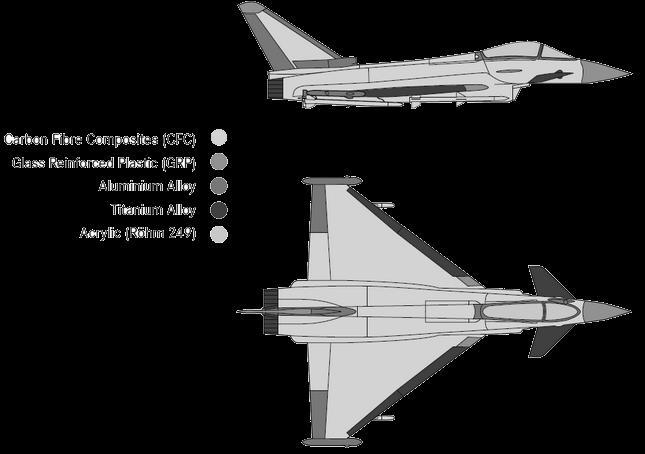
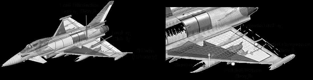
Carbon fiber composite materials are used extensivelyin many modern fighter aircrafts, such as Lockheed Martin F-35 Lightning, Eurofighter, Rafael and Saab Gripen.Carbon fiber materials are among the most widely usedin various elements of load-bearing structure of aircraft, such as, (1) wing skin; (2) flaperons; (3) vertical stabilizer; (4) fuselage; and tailplane [22-25]. Eurofighter Typhoon, about 40% of the structural weight is carbon fibre reinforced composite material (figure 1). Weight savings may increase payload-range capability, provide the opportunity to downsize subsystems at a constant performance level, or allow for better fuel efficiencies. Another example is the American fifth-generation fighter F/A-22, the world's most advanced aircraft, uses composite materials in the most important parts of the fuselage, wings, and tail. In fact, titanium alloy makes up 40% of the total weight of this military aircraft, and composite materials make up 34% [26] These areas are responsible for aerodynamic lift. Moreover, the structural strength and durability of these composites prompted the development of other aircraft components. The stealth aircrafts today are made of carbon fiber reinforced polymers because of the superior properties of carbon fibers that help reducing heat radiation and radar reflections [27]. Figure 2 depictsthe CFC-wing intended for the Eurofighter, which is attached to the fuselage by bending and shear fittings. The torsion box consists of the load carrying skins and the shear carrying spars and ribs which are bonded to the lower skins.
Providing performance guarantees of the structure, the main criteria for the box design must be assured. Mechanical properties of the carbon fiber composite, such as, high tensile and
Advances in Materials Science and Engineering: An International Journal (MSEJ), Vol. 5, No.2/3/4, December 2018
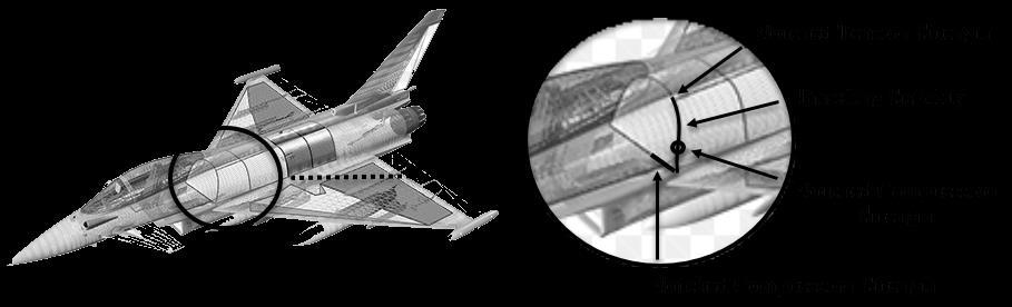
compressive elastic modulus, high notched tensile and notched compressive strength of the carbon fiber composite, offershigh flaperon efficiency, sufficient buckling stability of skins and spar webs, as well as, high bearing strength for load introductions [28, 29]. Figure 3 shows a typical of the structure of the front fuselage in the cockpit area and it demonstrates how here too the same criteria as for the wing are mainly valid.
Figure 3. Typical section of carbon fiber fuselage.
During manufacture or service, the structure is generally prone to foreign object damage, which may generate barely visible delamination’s in the carbon fiber composite and which may lead to a reduction of compression strength. Coats et al.[30] and Hintze et al.[31] have demonstrated that delamination can proceed at different processes, mainly as a result of impact damage. In this case, delamination cannot usually be detected from the impacted face. It has been found that, delamination considerably reduces compressive properties since the structure behaves as a series of thin struts rather than the original thick section [32, 33].
Compression after impact strength is another important requirement concerning stressing.The Fig. 4 presents the reduction of the compressive strength of delaminated specimen as the initial delamination area increases. The larger the hole, the higher the stressed region surrounding the hole, which reduces the strength of the material due to flaw.This can be explained by the failure modes [34-37]. When compressive loads are applied to the test specimen of smaller delamination area, the delamination will grow and induce local buckling and failure [38-39]. As CFC-laminates are very susceptible to notches in relation to static strength, unlike metallic materials, is elastic to failure and therefore local yielding around notches (bolt holes, cut-outs, etc.) cannot take place (Fig. 5). The laminate notched strength is affected by notch size [40, 41].
In a notched quasi-isotropic laminate, local buckling may occur, which leads to premature fracture [41]. Therefore, the main dimensioning criteria for the airframe structure of a fighter aircraft made of CFC are, tensile and compressive elastic modulus, notched tensile and compressive strength and compression-after impact strength (CAI). Moreover, the strength reduction in open hole compression is not as severe as in tension, possibly because the neat compression strength itself is significantly less than in the tension and already accounts for some of the strength reducing features in compressive state of stress [42]. Furthermore, in a humid environment, the matrix material absorbs moisture and degrades, giving less support to the fibers. Some of the above properties degrade with moisture and temperature, the worst combination of dry/wet condition and cold/hot environment has to be considered [43, 44]. This assumes that the part will be fully saturated with moisture and operating at elevated temperature. Nowadays, such properties are investigated in order that weight savings can be optimized.
600
500
400
300
700 Failure Stress (mm 2 )
200
100
Material:T300/914C QuasiisotropicLay-up
0 1000 2000 3000 4000 5000 0
InitialDelaminationArea(mm2)
500
400
300
600 s 2 (N/mm 2 )
200
100
Material:T300/914C Lay-Up:47/47/6% TestCond.:123oC/1%Moisture
Figure 4. Compression after impact strength vs. initial delamination area. 0 2 4 6 8 10 12 0
HoleDiameter(mm)
Figure 5. Notched tension strength of a carbon fiber composite laminate
If the manufacturing requirements are met, a final evaluation of the different semi-finished products can be carried out only by looking at the total structural weight implications. Therefore, all aircraft components made from carbon fiber composites (e.g. wing, fuselage, fin) have been preliminary stressed and the contribution of the above properties to the overall composite structural weight is given as follows:
Tensile modulus 0o = 7%
Compressive modulus 0o = 40%
Open hole tension strength = 15%
Filled hole compressive strength = 22%
Bearing strength = 11%
Compression after impact strength = 5%
3. STRENGTH REQUIREMENTS FOR CARBON FIBER COMPOSITES
6
5
4
3
2
1
Carbon fibers of the first generation, when introduced to the airframe construction of airplanes, were characterized by high specific elastic modulus and by high specific strength, whereas elongation at failure was relatively low (at about 1%). Carbon fibre composites offer many advantages compared with conventional metallic materials as aluminum and titanium. The main advantage of the use of composites in aerospace applications is the resultant weight reduction. For instance, by replacing aluminum alloy with carbon fiber reinforcement composite, the weight can be reduced 12% [45]. This weight saving may be used to reduce fuel consumption or increase the payload, maneuverability and speed [46]. Additional benefits include the superior fatigue and corrosion resistance of composites and their vibration damping properties. Meanwhile an increase of strength fig. 6, for carbon fibers was achieved by: (1) higher purity and reduction of weak points of the uncarbonized fibers; (2) improved manufacturing tolerances and higher straining during production of the fibers. 150 300 450 600 0
Figure 6. Development
of carbon fibers.
The shortfalls of the original epoxy resins were relatively high moisture absorption, (Fig. 7) and sensitivity to temperature in the presence of moisture, (Fig. 8), leading to a premature softening of the matrix (reduces the glass transition temperature) For wet conditions(70oC/85% RH, fig. 7), T300/914 gains more weight in a less time. Although, both composite materials shown Fickian diffusion behavior with the mass increasing with the exposure time, until composites become saturated with water. Generally, moisture increases the flexibility and ductility of resin/adhesive [47] and decreases elastic modulus and strength [48-51].Therefore, it is not allowed to confer the high compression strength of carbon fiber composite. However, in certain polymers, positive moisture effect could be observed. In fact, if the loss of low molecular weight substances in the polymer upon water absorption is more significant than water plasticization effect (depresses the glass transition temperature), the elastic modulus upon moisture ageing can be increased [52].
Advances in Materials Science and Engineering: An International Journal (MSEJ), Vol. 5, No.2/3/4, December 2018
2.0
1.8
1.6
1.4
1.2
1.0
0.8
2.2 Weight Gain (%)
0.6
0.4
0.2
914C Narmco5245
0 50 100 150 200 250 300
Time(Days)
Figure 7. Moisture uptake of first- and second-generation epoxy resins.
9x10⁴
8x10⁴
7x10⁴
Shear Modulus G o (MPa)
6x10⁴
5x10⁴
4x10⁴
3x10⁴
2x10⁴
1x10⁴
Ciba914C Narmco5245
0 50 100 150 200 250
Temperature(oC)
Figure 8. Temperature behavior of different carbon fiber composite materials (Glass transition temperature-Test Wet).
Moisture induces swelling, which means that residual stresses are modified in addition to the thermal stresses produced during curing process of the composite material [53]. As for the shear storage modulus, is also a function of moisture content. Shear modulus is starting to decrease between 90-120oC (fig. 8). The wetted test samples are tested at moisture barrier bag, while the results were validated with the torsion pendulum technique.
4. MANUFACTURING REQUIREMENTS AND PROCESSES FOR CFC
In order to improve CFC, new manufacturing processes must be developed. Part and assembly should be optimized, to assure the minimum cost and reliability of the structure In aircraft industry, there is a high demand for lowering fuel consumption [54, 55] and environmental impact [56]. Weight reductions must be achieved in a cost-effective way, and this is only achievable by a considerable communication between designers and manufacturing engineers, which may act as a unit [57, 58]. Although, there must be also a considerable reduction of the number of detail parts (and fasteners) [59] The properties of a composite part depend not only on the constituent materials, but also the processes used to consolidate them into final parts for assembly. The processes (manufacturing techniques) depend on the basis of chemical properties, and are distinguished, mainly in three different categories, (1) semi-finished fabrication; (2) open forming (layup, spray up, filament winding, pultrusion, automated fiber placement, curing); and (3) closed forming (injection molding, resin transfer molding, vacuum assisted resin infusion, compression molding). During manufacturing process, voids and shrinkage must be avoided. Voids and porosity are one of the most critical problems during the manufacturing process [60, 61]
It is proposed, thatprimary structures (wings, fuselage) must be resistant to fatigue and environmental effects (expensive materials). These two properties increase the cost of manufacturing process On the other hand, in secondary structures may be used cheaper materials and quicker manufacturing processes. Components such as wings must be meet strenuous stiffness and strength needs by controlling the orientation of the fibers with respect to the design loads [62].
Prepreg carbon fiber composites are used mostly in aviation industry, because of their advance properties. In order to achieve that, hot melt process, as well as, solvent dip process, were used. The first one, is a two-stage process (a) pre-lamination of a substrate paper; and (b) impregnation of the fibers. In the second process, the solvent content could be reduced, as the impregnated reinforcement passes through a heating oven.
5. USEFUL COMPARISONS AMONG DIFFERENT SUPPLIERS FOR CFCPREPREGS
The reliability of the airframe structure of the aircraft depend mainly on the structure and the material properties. Carbon fibers usually are classified in categories, as ultra-high modulus (UHM>450GPa), high modulus (HM between 350-450GPa), intermediate modulus (IM between 200-350GPa), low modulus (100GPa, tensile strength>3GPa) and super high tensile (tensile strength>4.5GPa) [63, 64, 65]
Suppliers offered their prepregs with intermediate modulus carbon fibers (table 1). A nonoptimum fiber translation is quite difficult to obtain, because of a different microstructure, which depends on the precursors and processing conditions. In the literature there are many different models [66-71]. It should be noted, that carbon fibers based on precursors fiber materials can be classified, as Rayon-based carbon fibers, Isotropic pitch-based carbon fibers, Gas-phase-grown carbon fibers, Mesophase pitch-based carbon fibers, as well as, PAN-based carbon fibers, and Pitch-based carbon fibers (fig. 9).
Finally, according to final heat treatment temperature, carbon fibers are classified into three classes: (1) Type-I, high-heat-treatment carbon fibers (HTT); (2) Type-II, intermediate-heattreatment carbon fibers (IHT); (3) Type-III, low-heat-treatment carbon fibers [55-59]. These
Advances in Materials Science and Engineering: An International Journal (MSEJ), Vol. 5, No.2/3/4, December 2018
properties also depend upon precursor, and processing technology. However, suppliers may help customers to reduce manufacturing time and cost-effectiveness, as well as, to improve efficiency and performance of the structures. Composites materials must be designed foruse in highly demanding environments Grade Tensile Modulus (GPa)
Tensile Strength (GPa) Country of Manufacture
T800 294 5.94 France/Japan M30S 294 5.49 France IMS 295 4.12/5.5 Japan MR40/MR50 289 4.4/5.1 Japan IM6/IM7 303 5.1/5.3 USA IM9 310 5.3 USA T650-42 290 4.82 USA T40 290 5.65 USA
3,0
2,5
2,0
1,5
1,0
3,5 Compression Strength (GPa)
0,5
TensileModulus(GPa)
Pitch-1 Pitch-2 PAN-1 PAN-2
Table 1 Strength and modulus of commercial PAN-based Carbon Fibers (intermediate modulus 265320GPa) [72]. 100200300400500600700800900 0,0
Figure 9. Tensile modulus vs. compression strength for two types of precursors.
6. SUMMARY AND CONCLUSIONS
Even though carbon fiber reinforced composites are becoming competitive and cost effective compared to metals, advancedtechnologies must be developed to reducemanufacturing time, while improving efficiency and cost-effectiveness, compared to metal components. Composites materials must be designed foruse in highly demanding environments and should be resistant to
Advances in Materials Science and Engineering: An International Journal (MSEJ), Vol. 5, No.2/3/4, December 2018
fatigue.Minimal defects improve the quality of the product. Carbon fiber composites have very light weight, providing high strength to weight ratio, but the mechanical properties depend on several factors, such as, the stacking sequence, and the ply thickness.In aviation industry, by selecting the best suited material a weight saving between 2.7 and 5.6% of the carbon fiber composite structure weight of a modern fighter aircraft can be achieved. Moisture absorption is another important issue, which leads a premature softening of the matrix. Further on, reduces the strength of the material. Further work needs to be done to establish that fiber thermosets will be used as structural material for modern fighter aircrafts to a large extent.
Statement
This research received no specific grant from any funding agency in the public, commercial, or not-for-profit sectors.
REFERENCES
[1] Brown, G, (2014),“The use of composites in aircraft construction”,http://vandaair.com/2014/04/14/the-use-of-composites-in-aircraft-construction.
[2] Åström,BT, (2002), “Manufacturing of Composite Polymers”, Stockholm, Sweden, Nelson Thornes Ltd, 2002, pp. 3-5.
[3] Åström,BT, (2002), “Manufacturing of Composite Polymers”, Stockholm, Sweden,
[4] Stockholm, Sweden, pp. 92-95.
[5] Hallander, P,(2007), “COMPRASER COMPOSITE COURSE -Material and manufacturing”, Stockholm, Sweden.
[6] Soutis, C, (2005),“Carbon fibre reinforced plastic in aircraft construction”, Materials Science and Engineering. A 412, pp. 171-176.
[7] Edwards, T, (2008),“Composite materials revolutionize aerospace engineering”,Ingenia 36, pp.24-28.
[8] Carbon Thermoplastic (CFRTP) Composites Market Analysis By Raw Material (PAN, Pitch), By Application (Automotive, Aerospace & Defense, Wind Turbines, Sport, Construction, Marine), And Segment Forecasts, 2018 – 2025
[9] Åström BT, (2002), “Manufacturing of Composite Polymers”, Stockholm, Sweden, Nelson Thornes Ltd, pp. 95-97.
[10]Grimshaw, MN, (2001),“Automated tape laying”, Cincinnati: Cincinnati Machine.
[11]Evans, DO, (1997),“Fiber placement”, Cincinnati: Cincinnati Machine.
[12]Åström,BT, (1997),“Manufacturing of polymer composites”, London, UK: Chapman & Hall.
[13]Campbell, FC,(2004), “Manufacturing processes for advanced composites”, Oxford, UK: Elsevier Advanced Technology.
[14]Gutowski, TG, editor, (1197),“Advanced composites manufacturing”, New York: John Wiley & Sons, Inc.
[15]Sloan, J,(2008), “ATL and AFP: defining the megatrends in composite aerostructures. High performance composites”, Gardner Publications.
[16]SKYFLEX Prepreg (2014), Materials selection guide, SK Chemicals
[17]Hallander, P, (2016), “Towards defect free forming of multi-stacked composite aerospace components using tailored interlayer properties”, Stockholm, Sweden, KTH, pp. 1-44.
[18]Suresh,.S, Mortensen,.A, (1998), “Fundamentals of Functionally Graded Materials”, IOM Communications, London.
[19]Miyamoto, Y, Kaysser.WA, Rabin, BH, Kawasaki,.A, Ford.R. G, (1999), “Functionally Graded Materials: Design, Processing and Applications”, Kluwer Academic, Dordrecht.
[20]Bielawski, R, (2017) “Composite materials in military aviation and selected problems with implementation”. Review of the Air Force Academy. No. 1 (33), pp. 11-16. DOI: 10.19062/18429238.2017.15.1.2
[21]Myriam Andrea Tarazona Romero, (2014), “State of the art of degasification techniques, in the shaping processes of composite materials prepared by Resin infusion”,UniversitatPolitècnica de CatalunyaBarcelonaTECH. Master’s in aerospace science &Technology.
Advances in Materials Science and Engineering: An International Journal (MSEJ), Vol. 5, No.2/3/4, December 2018
[22]Kang, W, Hwang, IS, (2011), “Commercial transport aircraft composite wing box trade study”. 18th International conference on compositematerials.
[23]Åström, BT, (2002), “Manufacturing of Composite Polymers”, Stockholm, Sweden, Nelson Thornes Ltd, pp. 6-11.
[24]Jacob, CG, Michael Starbuck, J, Fellers, JF, Simunovice, Srdan., Boeman, RG, (2004), “Strain Rate Effects on the Mechanical Properties of Polymer Composite Materials”, Journal of Applied Polymer Science. Vol.94, pp.296- 301.
[25]Barre, S, Chotard, T, and Benzeggagh, ML, (1996), “Comparitive Study of Strain Rate Effects on Mechanical Properties of Glass Fiber-Reinforced Thermoset Matrix Composites”, Journal on Composites-Elsevier. Vol. 27, pp.1169-1181.
[26]Hosur, MV, Alexander, J, Vaidya, UK, and Jeelani, S, (2001), “High Strain Rate Compression Response of Carbon/Epoxy Laminate Composites”, Journal of Composite Structures. Vol.52, pp. 405417.
[27]Gay D, (2015), “Composite materials: Design and applications”, 3rd ed. CRC Press/Taylor & Francis Group.
[28]Younossi O, Kennedy M and John CG,(2005),“Lessons Learned from the F/A–22 and F/A–18E/F Development Programs”, (Santa Monica, Calif.: The Rand Corporation, MG-276).
[29]Toubal, L, Karama M, (2004), “Stress Concentration in a circular hole in composite plate”. Composite Structures. Vol. 68.
[30]Soutis, C, Fleck, NA, Smith, PA, (1991),“Compression Fatigue Behaviour of Notched Carbon Fibreepoxy Laminates”, International Journal of Fatigue. 13(4), pp.303-312.
[31]Coats, TW, Harris, CE, (1999), “A Progressive Damage Methodology for Residual Strength Predictions of Notched Composite Panels”, Journal of Composite Materials. 33(23),pp. 2193-2224.
[32]Hintze, W, Hartmann, D. &Schütte, C, (2011),“Occurrence and propagation of delamination during the machining of carbon fibre reinforced plastics (CFRPs) –An experimental study”, Composite Science and Technology. Volume 71, pp. 1719-1726.
[33]Hiroshi, S, (1991), “Compressive behavior of fiber reinforced composite plates with a center delamination”, Advanced Composite Materials. Vol. 1 (1), pp. 23-37.
[34]Richardson, MOW, Wisheart, MJ, (1996), “ Review of low-velocity impact properties of composite materials”, Composite Part A: Applied Science.Vol. 27A, pp. 1123-1131.
[35]Sanchez-Saez, S, Barbero, E, Zaera, R, Navarro, C, (2005),“Compression after impact of thin composite laminates”, Composite Scienceand Technology. Vol. 65(13), pp.1911–1919.
[36]Sala, G, (1997),“Post-impact behaviour of aerospace composites for high-temperature applications: experiments and simulations”, Composite Part B.Vol. 28(5–6), pp. 651–665.
[37]Bull, PH, Edgren, F, (2004),“Compressive strength after impact of CFRP-foam core sandwich panels in marine applications”, Composite Part B.Vol. 35(6–8), pp. 535–541.
[38]De Freitas, M, Reis, L, (1998),“Failure mechanisms on composite specimens subjected to compression after impact”, Composite Structures.Vol. 42(4), pp. 365–373.
[39]Ishikawa T, Sugimoto S, Matsushima M, Hayashi Y. Some experimental findings in compression-afterimpact (CAI) tests of CF/PEEK (APC-2) and conventional CF/epoxy flat plates. Compos Sci Technol 1995;55:349–63. http://dx.doi.org/10.1016/0266-3538(95)00079-8.
[40]Zhang, X, Hounslow, L, Grassi, M, (2006),“Improvement of low-velocity impact andcompression-afterimpact performance by z-fibre pinning”, Composite Science and Technology. Vol. 66, pp. 2785–94.http://dx.doi.org/10.1016/j.compscitech.2006.02.029.
[41]Sheikh - Ahmad, JY, (2009a),“Conventional Machining of FRPs. In: Machining of Polymer Composites”,s.l.:Springer US. pp. 143-235.
[42]Coats, TW, Harris, CE, (1999),“A Progressive Damage Methodology for Residual Strength Predictions of Notched Composite Panels”, Journal of Composite Materials.V. 33 (23), pp. 2193-2224.
[43]Soutis, C, and Lee, J, (2008),“Scaling Effects in Notched Carbon Fibre/Epoxy Composites Loaded in Compression”, Journal of Materials Science. V. 43,pp. 6593-6598.
[44]Ekvall, JC, GriffinCF, (1981), “Design allowable for T300/52087 Graphite epoxy Composite Materials”, AIAA Meeting Paper. No 81–0541, pp 416–422.
[45]Potter, RT,Purslow,D, (1983), “Environmental degradation of notched CFRP in compression”, Composites. V. 14, No 3, pp 206–225.
[46]Purslow, D, Potter, RT, (1984), “The effect of environment on the compression strength of notched CFRP”, Composites. V. 15, No 2, pp 112–120.
[47]Rohitg, S, Dalu, RS, (2018), “Performance evaluation of different evaluation of different types of composite materials in aerospace applications: A review”. V. 6 (4), pp. 32-38.
Advances in Materials Science and Engineering: An International Journal (MSEJ), Vol. 5, No.2/3/4, December 2018
[48]Kelly, A., (1987), “Composites for the 1990’s”, Philosophical Transactions of the Royal Society, London. A322, pp. 409-423.
[49]Abdel Wahab MM, Crocombe AD, Beevers A, Ebtehaj K, (2002),“Coupled stress-diffusion analysis for durability study in adhesively bonded joints”, International Journal of Adhesion and Adhesives. V 22(1), pp. 61-73.
[50]Ashcroft IA, Abdel Wahab MM, Crocombe AD, (2003),“Predicting degradation in bonded composite joints using a semi-coupled finite-element method”, Mechanics of Advanced Materials and Structures. V. 10(3, pp.227-248.
[51]Papanicolaou, GC, Charitidis, PJ, Mouzakis, DE, Jiga G, (2015),“Experimental and numerical investigation of unbalanced boron/ epoxy-aluminum single lap joints subjected to a corrosive environment”, Journal of Composite Materials. 2015, 0021998315571773.
[52]Papanicolaou,GC, Charitidis,P, Mouzakis,DE, Karachalios,E, Jiga,G, Portan,DV, (2016), ‘‘Experimental and numerical investigation of balanced Boron/Epoxy single lap joints subjected to salt spray aging”,International Journal of Adhesion and Adhesives. V. 68, 2016, pp. 9-18
[53]Ashcroft IA, Abdel Wahab MM, Crocombe AD, Hughes DJ, Shaw SJ, (2001),“The effect of environment on the fatigue of bonded composite joints, Part 1: Testing and fractography”, Composites: Part A. V. 32, pp. 45-58.
[54]Apicella A, Migliaresi C, Nicolais L, Iaccarino L, Roccotelli S, (1983),“The water ageing of unsaturated polyester-based composites: influence of resin chemical structure”. Composites. V. 14(4),pp. 387-392.
[55]Choi, HS,Ahn, KJ, Nam, JD, Chun, HJ, (2001),“Hygroscopic aspects of epoxy/carbon fiber composite laminates in aircraft environments”. Composites Applied Science and ManufacturingV.32, pp. 709–720.
[56]Airbus, 2014. Available at: www.airbus.com [Accessed February 2014].
[57]Boeing, 2014. Available at: www.boeing.com/boeing/commercial [Accessed February 2014].
[58]Frida Andersson, Astrid Hagqvist, Erik Sundin, Mats Björkman, (2014),“Design for Manufacturing of Composite Structures for Commercial Aircraft- the Development of a DFM strategy at SAAB Aerostructures”, Procedia CIRP 17,pp. 362 – 367.
[59]Dostaler, I, (2010),“Avoiding rework in product design: evidence from the aerospace industry”, International Journal of Quality & Reliability Management.pp. 5-26.
[60]Vianello, G, Ahmed-Kristensen, S, (2012),“A comparative study of changes across the lifecycle of complex products in a variant and a customized industry”, Journal of Engineering Design.pp.99-117.
[61]Archibald,DA, Shwarz,JW, Wanamaker,JL, (1989), “Proceedings of the AmericanSociety for Composites”, 4th.Tech. Conf., pp 593-601.
[62]Campbell, F, (2010g),“Processing Science of Polymer Matrix Composites”, Structural Composite Materials. s.l.:ASM International, pp. 201-234
[63]Mallick, PK, (2007c),“Manufacturing. In: Fiber-Reinforced Composites Materials, Manufacturing, and Design”. 3 ed. s.l.:CRC Press.
[64]Susan, A,Resetar, J, Curt Rogers, Ronald W. Hess,“Advanced airframe structural materials, A primer and cost estimating methodology”, United States Air Force. AD-A253 371. pp. 1-117.
[65]Chung, DL, (1994),“Carbon Fiber Composites; Butterworth-Heinemann: Boston, MA, USA. pp. 3–65.
[66]Donnet, JB, Bansal, RC, (1990),“Carbon Fibers”, 2nd ed.; Marcel Dekker: New York, NY, USA. pp. 1–145.
[67]Pooja B, Alka, G,(2017). “Carbon Fibres: Production, Properties and Potential Use”, Material Science Research India. Vol. 14(1), 2017, pp.52-57.
[68]Morley, JG, (1987),“High-Performance Fiber Composites”, Academic Press: Orlando, FL, USA. pp. 46–78.
[69]Wicks, BJ,(1975), “Microstructural disorder and the mechanical properties of carbon fibers. Journal of NuclearMateriasl.V. 56, 287–296.
[70]Watt, W, Johnson, W, (1969), “The effect of length changes during oxidation of polyacrylonitrile fibers on the Young's modulus of carbon fibers”, Applied Polymer SymposiaVol. 9, pp.215–227.
[71]Fourdeux, A, Perret, R,Ruland, W, (1971),“General structural features of carbon fibers”, In Proceedings of the First International Conference on Carbon Fibers, Plastics Institute: London. UK, pp. 57–62.
[72]Perret, R,Ruland, W,(1970), “The microstructure of PAN-base carbon fibres”, Journal Applied Crystallography. Vol. 3, pp. 525–532.
[73]Diefendorf, RJ,Tokarsky, E, (1975),“High-performance carbon fibers”, Polymer Engineering & Science. Vol 15, pp. 150–159.
[74]Gurit. Guide to composites. (http://www.gurit.com)
Advances in Materials Science and Engineering: An International Journal (MSEJ), Vol. 5, No.2/3/4, December 2018
[75]Bennett, SC, Johnson, DJ, (1979),“Electron-microscope studies of structural heterogeneity in PANbased carbon fibers”. Carbon. Vol.17(1), pp. 25–39.
[76]Edie, DD, (1998),“The effect of processing on the structure and properties of carbon fibers”, Carbon. Vol. 36(4), pp. 345–362.
[77]Guigon M, Oberlin A, Desarmot G, (1984),“Microtexture and structure of some high tensile strength PAN-based carbon fibers”, Fiber Science and Technology.pp. 55–72.
[78]Don, J, Ju, CP, (1990), “Basal plane orientation of polyacrylonitrile fibers in a commercial polyacrylonitrile–pitch carbon–carbon composite”, Material Science and Engineering A.V. 124, pp. 259–266.
Author
Panagiotis Charitidis is researcher at the Center of Orthopaedic Research (C.O.RE) at Center for Interdisciplinary Research and Innovation-Aristotle University of Thessaloniki (CIRI-AUTH)). He holds Ph.D in applied mechanics from the University of Patras. During this period, he is assistant professor at Democritus University of Xanthi (Greece).