Architectural Portfolio | Joshua Bright

Page 1

Architectural Portfolio

Thesis | Practice | Freelance

BA (Hons) MArch

Architectural Thesis

Birmingham City University

For full works, please see the full version of my thesis submission on my Issuu page

This is availble using the QR code foung on my Curriculum Vitae

3

Thesis statement Theory

My thesis aims to explore the role that the Non-Fungible Token has to play within the realm of architectural practice, but most notably the ability for the architect to provide their client with the ability of authenticating something that could either be tangible or intangible.

To form the foundation of this thesis, Coventry’s connection with 5 twin cities and their typographies has been explored, drawing inspiration from the Nolli Map process, with the aim of forming an interpretation of the Roma Interrotta and Kintsikuroi that can be used to form a set of connecting artefacts between the cities, building on the Kintsugi narrative. These artefacts are intended to strike up a sentimental connection via the tangible and intangible artefacts through the ideology of personal ownership and tenure, which is why the authentication of a unique artefact through the NFT process is so vital to this projects success.

The thesis proposal will create what is commonly referred to as a Freeport within which this process of forming the NFT is carried out, with the aim of distributing the produced artefacts out to residents of the twinned cities. In order to create these NFTs, occupants from each twinned city will be expected to carry out a process of data collection and archival processes which have been refined in my earlier process work, which will form the foundation of the artefacts created within this facility.

To take this process a stage further, the role of the architectural vessel will be explored as an aid to this thesis statements narrative, exploring how the demolition process can be carried out during a structure habitation, with the demolition process becoming somewhat of a live installation, morphing and changing the architectural devices with each element it demolishes.

To conclude, the final aim for this thesis is to deliver a set of physical artefacts cast to represent the six cities which come together to create a structure which then doubles as a form of vault within which the original of each artefact is stored. Occupants of each twin city will be granted ownership of a generated NFT based on elements from each artefact, this only they will have the authentic version of, aiming to rekindle the connections that the twin cities initiative was intended to create.

Project Introduction Application

My project seeks to transform the existing Ikea building of Coventry into the National Freeport for Twinning, drawing inspiration from the way that the Freeport is portrayed in the film “Tenet” as a hub for the artistic underworld. In contrast, the NFT will seek to do the opposite, becoming a beacon of the production process within its surrounding context.

This facility will be responsible for the manufacturing, processing, scanning and storage of a number of bespoke non-fungible tokens that are to be mass produced and distributed to residents of 5 twinned cities with Coventry, based on the twins city initiative that Coventry helped to co-found. Those cities being:

The use of the NFT in this project is specifically to allow the residents a method of verifying the validity of their artefact via the use of an encoded block chain into the main image, and is not being applied as a rudimentary art form.

4
1. Dresden 2. Graz 3. Sarajevo 4. Bologna 5. Ostrava

Location Plan

1:10,000 @ A3

Located along the inner section of the Coventry ring road, my site sits within close proximity to a number of iconic Coventry landmarks. Through the alleyway sitting perpendicular to Croft Road, the site is directly connected to Spon Street. Famous for its historical link with the trades of Coventry, Spon Street was once home to the city’s Dyers, Tanners and Watchmakers, defining the area as a landmark for production. In contrast, across Queen Victoria Road to the east sits the Coventry Market, locally considered to be the original keystone of trade within the area. This connection between both production to the north and distribution to the east provides me with the ideal location to support my thesis proposal, both physically and ideologically.

Site Plan Scale @ 1:2,000

As the proposal is situated within the structure of the existing Ikea building, which has been selected to form a new Arts Centre as part of Coventry’s role as the 2021 City of Culture, the proposal will not form any new issues within its surrounding context and will instead transform what has become an eyesore of the city into a thriving hub of production, innovation and collaboration that will grant the site a new lease of life. This is further strengthened by the fact that the current structure sits within what is mainly considered a commercial area with shops, pubs and venues located around the Northern, Eastern and Western boundaries of the site.

5 UPPER YORK STREET HERTFORD WinslowHouse RINGWAY QUEENS RINGWAY RUDGE REGENT MEADOW GivensHouse Fennell House QUEEN'SROAD STREET Queen's STREET Trafalgar REGENT GROSVENOR ROAD WESTMINSTERROAD COUNDON STREET MIDD BOROUGHRO 23a MILL STREET Shakespeare PERCY STREET MEADOW STREET SunnyBank ABBO GLOUCESTE ST NORFOLKSTR GospelHall DOVER STREET Clovelly 83a Brookville MIDD OROUGHROAD COUNDONROAD Windmill Meeting CLOSE BARRAS WATCH LOWERHOLYHEADROAD MERIDEN STREET Court 21a HILLSTREET (PH) RINGWAYHILLCROSS WarwickRoad (PH) Thomas White's RINGWAY QUEENS Church GREYFRIARSROAD SHERIFFSORCHARD Statue Three Tuns EATON ROAD STCOLUMBA LOSE STCOLUMBA'SCLOSE HILLSTREET Johnthe 188 estored) CHAPEL Shelter CORPORATION STREET Baptist'sChurch (above) LAMB 29 BoroConst WardBdy BoroConst WardBdy BoroConst Ward BoroConst Bdy CROFTROAD ROVERROAD BONDSTREET The Skydome Grosvenor House RYLEY STREET MANOR HOUSE Maga WellStr Gate HoltCourt Beauchamp House SM The Quadrant CityWall UPPER WELL STREET Bond's spital GWAYSTNICHOLAS RINGWAYHILLCRO UPPERHILLSTREET Freemens WarwickRow WarwickRow Walk 51 (Remai Mews QUEENS RINGWAY Retail Park Osburg's Mareaux Catholic Primary and Nursey Schoo (above) Market Chambers Bablake Hospital Lower Precinct (Coventry University) Gantry Shelter Gantry Grey Friars Green RINGWAY RUDGE Coventry Foyer FLEETSTREET Osburg's City Village One Friargate 14 Subway Subway Coventry Jesus Centre Tunnel Subwa The Shelter Central Buildings Rising Car Park STATIONSQUARE
16 36 HERTFORD PLACE RINGWAY QUEENS 6 STARLEY ROAD 21 46 Posts 23 18 SPON STREET 169 Shakespeare 171 TCB 32 3c 15 14 1 24 9 13 13 163 (PH) 17 LB 16 29 PH 182 Old Windmill Meeting House 172 164 CLOSE 9 166 Warehouse WATCH LOWERHOLYHEADROAD Court No 7 3d 25 to 27 80.2m (PH) Club 21 3 3a 2 38 31 10 TCB 35 13 12 2 37 Albert Buildings LB 3 41 33 12to 14 27 Place HILLSTREET StJohnthe 25 188 PH 26 PH 190 Lidice Baptist'sChurch 79.6m (site of) Bonds Hospital Almshouses 29 58 55 17 54 CROFTROAD ROVER ROAD BONDSTREET QUEEN VICTORIA ROAD El Sub Sta 15 50 56 Spon Gate 96 Court Vicroft SM 40 28 11 CityWall Bond'sHospital Monument 85 to 101 Almshouse Bonds Court 16 181 3e 12 Ramp TCBs 3331 3735 514943474541 39 (RemainsOf) Twr BablakeBoys' Hospital Shelters Shelter Shelter Shelter Twr 79.6m Car Park Coventry Foyer FLEET STREET Car Park Collard Tunnel Penny Centre The Arena (Ice Rink) Electricity Distribution Site Bonds Lodge (site of) Hill Gate House Ringway Micro Macro Heterodox Orthodox

Secondary source assemblage

Archiving

via the “poor image”

To review and test the narrative portrayed by E-Flux’s “In defense of the poor image”, I elected to test the archiving process of an available texture source using Blender as my primary tool, extracting the texture from the original image, then using photoshop to create a Bump and Normal map from the texture in order to create an accurate 3D representation of this artefact. Within this there is a subtle reference to the reader, which states:

“The poor image is a copy in motion” - E-Flux

6
Primary resource
for reference |
by
Final render post processing Created by author
collage
Created
author Process timelapse
Sent to Coventry: the city of culture’s brutalist architecture Photographs by Andrew Fox Texture Bump Map Normal Map

Photogrammetry Test

Archiving via scanning

Reverting back to a more digital process, I carried out a number of photogrammetry tests throughout Coventry in an attempt to capture a number of contrasting artefacts throughout the city in order to further my understanding of archival methods. Most notably, this process allowed me to reflect on how user friendly and intuitive the archiving process now is for people to carry out for themselves.

This sparked the narrative in my mind where a collective of people would be enabled to come together, using artefacts and textures that they have scanned to form a number of celebratory art pieces that reflect their local community.

Additional tests

Process testing continued

Once it became clear how simple this process is to carry out, I decided to continue with this study in order to form a set of artefacts as opposed to a number of random elements from within the city. Each artefact seeks to reflect a differing rhetoric or period in the city’s history.

7
Meshroom Walkaround Data showcase Three Tuns Cathedral Steps Union Street Carpark Cavendish House AR Model

Artefact production process

From data to cast

The production process for the artefacts will be in the following stages:

1. Artefacts and elements from each city will be sent to the Freeport by residents to help with the production of the NFTs

2. A production line is set up in a section of the old Ikea building to cast these elements in concrete

3. These elements are then scanned/processed to be photogrammatised into a virtual model

4. The elements are then transferred into a custom-built storage facility to be held until the lifespan of the building is complete.

5. During the storage process, the building is marked for demolition and is slowly being torn apart

6. For most of its lifespan, the building remains in place as a form of monument to this initiative

7. Upon the end of the initiative’s lifespan, the building is then completely demolished, leaving in place the broken fragments of the NFTs within the rubble of the building to ensure they cannot be remade.

Production process test Small scale concrete casting

In order to test the validity of this production process, a number of test casts were produced using the same process as outlined for the production of the artefacts. Once I had decided on the set of datum to cast, a positive was created using clay sections and a deep timber picture frame which would allow me to cast the concrete into the desired form. In order to add a form of security via randomness, the concrete once poured in situ was left to terraform within the positive mould. In order to allow for the removal of the artefact once solid, the back section of the frame could be removed, and clingfilm was utilised to form a barrier between the positive mould and the negative cast.

This allowed for each artefact to have a distinct character, but also a sense that each cast produced using this process would be unique within its own process. Partly, this sense of low-resolution casting is a reference to my study when considering the “defence of the poor image” by E-Flux earlier in this thesis study.

Additionally, within this process, it allowed me to test the theory of the artefacts being demolished alongside the structure, with the remains of both left on site as a form of monolithic memorial to the initiative, as opposed to leaving the site in its original state once the process has been complete.

8

Structure reinforcing narrative

When working with an existing structure, it is imperative to maintain the structural elements and utilize them to house the new proposal. This allows for the fact that the building, as it stands in situ, has already been considered in terms of its effect on its context. By stripping back the existing form to just the main structural elements, the skeleton of its previous state lies in memorium to its past self, yet still supports the new proposal.

On a more technical note, the structural loading of the building once the proposal is in place will be significantly reduced. This then informs the demolition process which seeks to once again morph the form and structure of the new proposal.

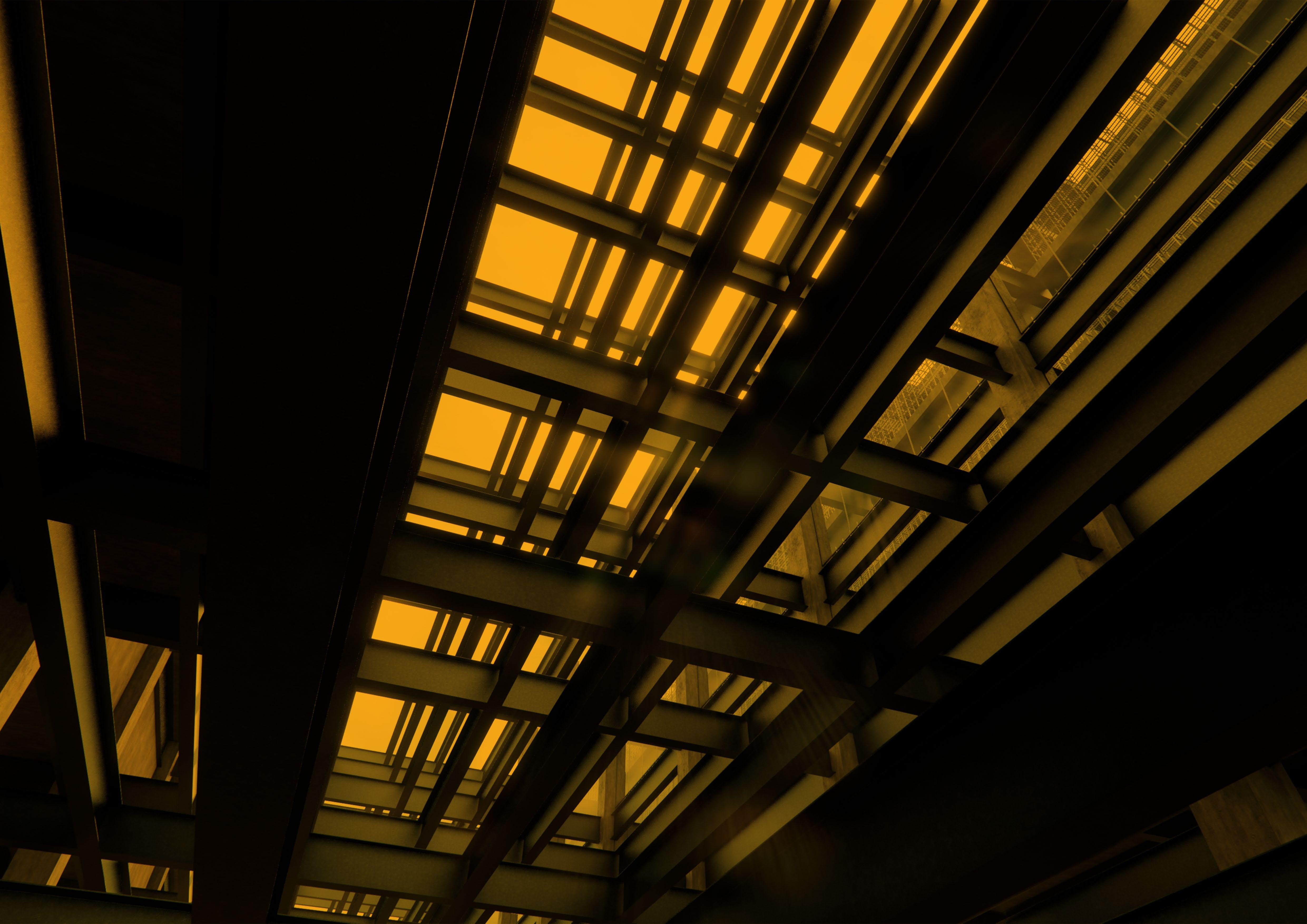
During this primary stage of the scheme, the building sits in its exposed structural state, where the old structural elements are juxtaposed against the newly installed cast in situ concrete walls and structure, and the expansive floor to ceiling height curtain walling granting passers by the ability to see into the production process.

Once the production process has finally been established and the running of the production line has begun, the existing structural elements that are no longer required are marked for demolition, providing the site with an even more vivid contrast between the sleek grey steelwork and the diagonally yellow marked demolition beams.

While the production and storage process is carried out, and once the predemolition phase has been completed, the demolition of the structure begins as a form of dynamic installation that surrounds and is forever changing the structure in place, given the site another layer of dynamicism to its original state.

In the post-demolition condition, the scheme almost lies in ruin, ripped to shreds during the demolition process with merely the required spaces left in place to allow for the process to continue. This stage would sit towards the end of the building’s lifespan, circa. 60 years post the buildings original construction date.

9
1. Proposal in situ Structure maintained in current state 2. Pre-demolition Phase Structure marked for demolition 3. Demolition Phase Demolition process commences 4. Post-demolition Condition Demolition complete Patronage of technology

Third Floor Plan Expanded

This plan outlines how the production process is clearly defined in the form of the building, utilizing the steel structure in place to define the boundary of the newly proposed spaces.

1:500 @ A3
1 2 4 5 3
*Stage 6 is carried out during the demolition stage

Sectional Drawing/Render

Highlighting process

This section shows how the process section are connected, with the first stages in the production to the left, the storage facility in the central portion of the building and the server room and the undercroft maintenance facility below.

Internal Render Facade effect on interior

As shown here, the casts placed on the facade of the building helps to add atmosphere into the internal spaces through the use of differing lighting conditions which are dynamic due to the ever-changing environment. This is further enhanced by the celestial nature of the facade casts, implying connotations of a spiritual and sacred space that the product facility is enclosed within.

Internal Render Celestial castings

As part of this project relies on the collection of data by residents of the 6 twinned cities, the central point of each defined area for collection will be the cities cathedral, reconnecting the other cities with the destruction of Coventry cathedral.

External Render

Pre-demolition stage

Prior to the demolition of the unused structural elements within the scheme, structural elements requiring demolition are marked ready for the process to commence. Additionally, to aid the process, two large scale cranes are positioned upon the roof of the scheme to enable to demolition process.

External Render

The demolition cranes are placed upon steel tracks allowing them to move along the building, making the demolition phase as easy and as safe as possible due to the site still being habitable throughout this period. This is done in order to avoid large cranes upon the site which may cause numerous safety issues. The cranes forming part of the scheme also adds to the rhetoric and performance of the demolition process.

Roof mounted demolition cranes

External and Internal Renders

Demolition commences

Once the scheme is reaching the end of its lifespan, the demolition stage will commence, with the unused steal work removed and taken for reuse within another scheme.

As shown in the image on the right, the ability to witness the demolition process from within the structure heightens the experience within the spaces, making for a dynamic and gripping space that is constantly changing.

26

Practice Work

Nicol Thomas Architects

No commentary provided as some of the works displayed are ongoing/active projects

27
Retirement Village competition submission Photoshop
29
1
2
3
1 4
2 5
6
7
1 2 3 4 5 6 7
Axonometric Apartment AutoCAD/SketchUp
Kitchen
Living Room
Bedroom
Bedroom
En-suite
Toilet
Modular Balcony

SketchUp/Photoshop

Site Block

The site is extruded and reduced to create a manageable and considerate form to its context.

Mitigation of Mass

Considering how we can best break up the site block to create public realms, connecting routes, gateways and viewing corridors to important contextual characteristics.

Rationalisation

Breaking apart the site block, as per the mitigation of mass, to create numerous forms and connecting routes to understand how best to use the site.

Orientation and Connectivity

Rotation of created forms, reacting to the shape of the site boundary. This also takes into consideration the sun path and prevailing winds to create a considered architectural response with regards to the climate.

30
Narrative diagramming

Narrative diagramming

SketchUp/Photoshop

Contextual Response

Reduction of mass as a direct response to the contextual parameters and surroundings of the site, most notably the adjacent residential zones to the north east.

Efficiency

Voided external atrium circulation to improve scheme efficiency and introduce more natural light and ventilation into the circulation spaces.

Greenhouses

Greenhouses are introduced on the top floor to further reinforce the opportunities for the Circular Economy to connect seamlessly within the scheme, and to function as intended.

External Amenities

Active green spaces are created within void spaces across the site, with habitable green roofs, allotments between blocks and open public squares added to create active green public realms and gateways.

31

Sectional diagram

SketchUp/Photoshop

Central community external spaces

Allotments

Simplistic Building Form

Efficient built form

External walkways

User controlled shading mechanisms

External active community

Naturally cooled Solar Panels

External walkways minimse built form and carbon footprint, encourage natural ventilation and create secondary external spaces for residents to meet and greet

Circular Economy

Roof top terrace encourages external activity and creates enjoyable spaces for residents

User controlled shading screens allow control on shading throughout the year

Landscape presents the principle aspect of the development encouraging users to utilise external spaces

Upper level greenhouses allow residents to plant and grow

External walkway

Encourages stack ventilation and natural cooling

Resident allotments allow users to plant, grow and consume produce on site minimises wastes and encourages recycling

AutoCAD/SketchUp

Focus on greeness and openess

Green walls

Planting beds

Allotment zones

Rooftop Greenhouses

Minimise perception of built form

1 Greenhouse 2. Pre-fab brick slip panel system 3. Bolt-on flexible balcony system 4. Sunspace balcony option 5. Green wall pre-fab panel 6. Brick pattern pre-fab panel Bay Elevation

Aspirational Sketch

SketchUp/Hand Sketch/Photoshop

Aspirational Sketch

SketchUp/Hand Sketch/Photoshop

Aspirational Sketch

SketchUp/Hand Sketch/Photoshop

AutoCAD/Photoshop

Bay elevations
38

Freelance Work

JBVJ Architects

39

Existing Ground Floor Plan

40 WC BEDROOM 1 LIVING ROOM DINING ROOM KITCHEN UTILITY GARAGE WC LOBBY
UP
ENTRANCE HALL
AutoCAD
41 Project Date Rev By Details UP GARAGE UTILITY LIVING ROOM PLAYROOM WC SNUG FOOTPRINT OF FLOOR ABOVE STEEL TO SE DESIGN ROOF LIGHT ABOVE ROOF LIGHT ABOVE ROOF LIGHT ABOVE 11384 7940 4159 5192 7760 KITCHEN DINING WC ENTRANCE HALL
Ground Floor Plan AutoCAD
Proposed
42 site boundary site boundary site boundary site boundary Site boundary line Existing Elevations - Sheet 1 SCALE 1:100 0 4 2 6 8m Existing North Eastern Elevation Existing South Western Elevations Date Client Drawing title Project Ref. Scale Drawing No. Checked Revision Project Date Rev By Details Notes Copyright this drawing is vested in the Architect and must not be copied reproduced without consent. Only figured dimensions are be taken from this drawing. All contractors must visit the site and be responsible for taking and checking all dimensions and levels relative their work. ALL DIMENSIONS TO BE CHECKED AND REVIEWED BY CONTRACTOR ON SITE All drawings be read conjunction with all relevant Structural and M&E Engineers drawings and specifications. Contractor Design Development: Details and general arrangement information contained within these drawings outlines the concept approach for materials, components and specialist systems only. Aspects the design require development not possible pre-construction phases the project. The main contractor and associated sub-contractors are required to develop and validate the detailed design accordingly conjunction with project specifications, surveys and environmental data is assumed that all works on this drawing will be carried out by competent contractor working, where appropriate, an approved method statement. Notify the Architect immediately of any significant variation between the principle and the clarified design. This drawing is copyright of JBVJ Architects. Contractor to notify Architect of any discrepancies or site variations immediately 2A Jervis Crescent, B74 4PW JsB 005 1:100 @ A3 22-195 Existing Elevations Sheet 1 Mr & Mrs Kandola 12.05.2022 N Existing Elevations AutoCAD

Proposed Elevations

43 site boundary site boundary Framing to match existing Brickwork to match existing Framing to match existing Brickwork to match existing Aluminium slimframe PPC Black Double height entrance curtain walling site boundary site boundary Framing to match existing Brickwork to match existing Framing to match existing Juliet Balcony Render to match existing White Aluminium slimframe PPC Black 6 Leaf sliding doors Aluminium slimframe PPC Black 3 Leaf sliding feature corner doors Stone Coping Framing to match existing Site boundary line Proposed Elevations - Sheet 1 SCALE 1:100 0 4 2 6 8m Proposed North Eastern Elevation Proposed South Western Elevations Date Client Drawing title Project Ref. Scale Drawing No. Checked Revision Project Date Rev By Details Notes Copyright this drawing is vested in the Architect and must not be copied reproduced without consent. Only figured dimensions are be taken from this drawing. All contractors must visit the site and be responsible for taking and checking all dimensions and levels relative their work. ALL DIMENSIONS TO BE CHECKED AND REVIEWED BY CONTRACTOR ON SITE All drawings be read conjunction with all relevant Structural and M&E Engineers drawings and specifications. Contractor Design Development: Details and general arrangement information contained within these drawings outlines the concept approach for materials, components and specialist systems only. Aspects the design require development not possible pre-construction phases the project. The main contractor and associated sub-contractors are required to develop and validate the detailed design accordingly conjunction with project specifications, surveys and environmental data is assumed that all works on this drawing will be carried out by competent contractor working, where appropriate, an approved method statement. Notify the Architect immediately of any significant variation between the principle and the clarified design. This drawing is copyright of JBVJ Architects. Contractor to notify Architect of any discrepancies or site variations immediately 2A Jervis Crescent, B74 4PW JsB 010 1:100 @ A3 22-195 Proposed Elevations - Sheet 1 Mr & Mrs Kandola 12.05.2022 N
AutoCAD
44 UP STEP DOWN existing ground floor 100m step up RECEPTION DINING LIVING ROOM KITCHEN STORE STORE Existing Ground Floor Plan AutoCAD
45 STEP DOWN UP proposed ground floor STUDY RECEPTION LIVING ROOM WC UTILITY ROOM ENTRANCE HALL LOBBY SNUG DINING SPACE KITCHEN STEP DOWN LOBBY DOUBLE SIDED FIREPLACE ABOVE PATIO WC LOBBY ROOF LIGHT ABOVE ROOF LIGHT ABOVE 7531 4150 4000 6000 5700 6335 3200 1343 1500 7884 4309 4300 2400 Proposed Ground Floor Plan AutoCAD

Existing Elevations AutoCAD

46 site boundary site boundary existing north west elevation site boundary site boundary existing south east elevation Date Client Drawing title Project Ref. Scale Drawing No. Checked Revision Project Date Rev By Details Notes Copyright this drawing is vested in the Architect and must not be copied or reproduced without consent. Only figured dimensions are be taken from this drawing. All contractors must visit the site and be responsible for taking and checking all dimensions and levels relative to their work. ALL DIMENSIONS TO BE CHECKED AND REVIEWED BY CONTRACTOR ON SITE All drawings to be read conjunction with all relevant Structural and M&E Engineers drawings and specifications. Contractor Design Development: Details and general arrangement information contained within these drawings outlines the concept approach for materials, components and specialist systems only. Aspects of the design require development not possible at pre-construction phases the project. The main contractor and associated sub-contractors are required to develop and validate the detailed design accordingly conjunction with project specifications, surveys and environmental data assumed that all works on this drawing will be carried out by competent contractor working, where appropriate, an approved method statement. Notify the Architect immediately of any significant variation between the principle and the clarified design. This drawing copyright JBVJ Architects. Contractor notify Architect any discrepancies or site variations immediately 88 College Road, B13 9LP JsB 004 1:100@A3 21-187 Existing Elevations Sheet 1 M Fiazan 03.02.22 Site boundary line Proposed Elevations - Sheet 1
0 4 2 6 8m
SCALE 1:100

Proposed Elevations

47 site boundary site boundary proposed north west elevation Brickwork to match existing Framing to match existing Framing to match existing Juliet Balcony Roofing tile to match existing Render White Brickwork to match existing Aluminium slimframe PPC Black Feature sliding door Aluminium slimframe PPC BlackThree leaf corner feature sliding door Aluminium slimframe PPC Black site boundary site boundary proposed south east elevation Brickwork - Painted white to match existing Brickwork to match existing Date Client Drawing title Project Ref. Scale Drawing No. Checked Revision Project Date Rev By Details Notes Copyright of this drawing vested the Architect and must not be copied or reproduced without consent. Only figured dimensions are to be taken from this drawing. All contractors must visit the site and be responsible for taking and checking all dimensions and levels relative to their work. ALL DIMENSIONS TO BE CHECKED AND REVIEWED BY CONTRACTOR ON SITE All drawings to be read in conjunction with all relevant Structural and M&E Engineers drawings and specifications. Contractor Design Development: Details and general arrangement information contained within these drawings outlines the concept approach for materials, components and specialist systems only. Aspects of the design require development not possible at pre-construction phases of the project. The main contractor and associated sub-contractors are required develop and validate the detailed design accordingly conjunction with project specifications, surveys and environmental data assumed that all works on this drawing will be carried out by competent contractor working, where appropriate, to an approved method statement. Notify the Architect immediately any significant variation between the principle and the clarified design. This drawing copyright JBVJ Architects. Contractor notify Architect any discrepancies or site variations immediately 88 College Road, B13 9LP JsB 008 1:100@A3 21-187 Proposed Elevations Sheet 1 M Fiazan 03.02.22 Site boundary line
Elevations - Sheet 1
1:100 0 4 2 6 8m
Proposed
SCALE
AutoCAD
48 existing south west elevation site boundary site boundary existing north east elevation site boundary site boundary Date Client Drawing title Project Ref. Scale Drawing No. Checked Revision Project Date Rev By Details Notes Copyright this drawing is vested in the Architect and must not be copied or reproduced without consent. Only figured dimensions are be taken from this drawing. All contractors must visit the site and be responsible for taking and checking all dimensions and levels relative their work. ALL DIMENSIONS TO BE CHECKED AND REVIEWED BY CONTRACTOR ON SITE All drawings to be read conjunction with all relevant Structural and M&E Engineers drawings and specifications. Contractor Design Development: Details and general arrangement information contained within these drawings outlines the concept approach for materials, components and specialist systems only. Aspects of the design require development not possible at pre-construction phases the project. The main contractor and associated sub-contractors are required to develop and validate the detailed design accordingly conjunction with project specifications, surveys and environmental data assumed that all works on this drawing will be carried out by competent contractor working, where appropriate, an approved method statement. Notify the Architect immediately of any significant variation between the principle and the clarified design. This drawing copyright JBVJ Architects. Contractor notify Architect any discrepancies or site variations immediately 2 Sandpits Close, B76 9EZ JsB 003 1:100@A3 22-190 Existing Elevations Sheet 1 J Sunner 15.02.2022 Site boundary line Existing Elevations - Sheet 1
Elevations AutoCAD
SCALE 1:100 0 4 2 6 8m Existing

Proposed Elevations

AutoCAD

0 4 2 6 8m

SCALE 1:100

Proposed Elevations - Sheet 1

49 Roof Light Framing to match existing Framing to match existing Brickwork to match existing Roofing tile to match existing Framing to match existing Brickwork to match existing site boundary site boundary Roofing tile to match existing Framing to match existing Brickwork to match existing site boundary site boundary Date Client Drawing title Project Ref. Scale Drawing No. Checked Revision Project Date Rev By Details Notes Copyright of this drawing vested the Architect and must not be copied or reproduced without consent. Only figured dimensions are to be taken from this drawing. All contractors must visit the site and be responsible for taking and checking all dimensions and levels relative to their work. ALL DIMENSIONS TO BE CHECKED AND REVIEWED BY CONTRACTOR ON SITE All drawings to be read in conjunction with all relevant Structural and M&E Engineers drawings and specifications. Contractor Design Development: Details and general arrangement information contained within these drawings outlines the concept approach for materials, components and specialist systems only. Aspects of the design require development not possible at pre-construction phases of the project. The main contractor and associated sub-contractors are required develop and validate the detailed design accordingly conjunction with project specifications, surveys and environmental data assumed that all works on this drawing will be carried out by competent contractor working, where appropriate, to an approved method statement. Notify the Architect immediately any significant variation between the principle and the clarified design. This drawing copyright JBVJ Architects. Contractor notify Architect any discrepancies or site variations immediately 2 Sandpits Close, B76 9EZ JsB 006 1:100@A3 22-190 Proposed Elevations Sheet 1 J Sunner 15.02.2022 Site boundary line
50 Architectural Portfolio Joshua Bright Part II Architectural Assistant | BA (Hons) | MArch

Turn static files into dynamic content formats.

Create a flipbook
Issuu converts static files into: digital portfolios, online yearbooks, online catalogs, digital photo albums and more. Sign up and create your flipbook.