dystopian utopia dystopian utopia dystopian utopia

LAU ENCI JONATHAN
DEPARTMENT OF ARCHITECTURE, NATIONAL UNIVERSITY OF SINGAPORE
AY 2022/23 YEAR 2 DESIGN 3 SEMESTER 1
AR2101 ARCHITECTURE DESIGN 3: AGGREGATION, STRUCTURE, SPACE
UNIT 1: CUBOID EXPOSITIONS
VICTOR LEE STUDIO
SUMMARY
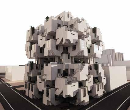
In this project, I aim to create a dwelling along a green space along the intersection of Kampong Kapor Road and Rowell Road. My final desired outcome was to create a building which could do two main things. Firstly, I wanted to create something which could blend in with the rest of the site. This means that the dwelling spaces should be able to follow similar analogs and be able to draw features associative in nature, following the spatial order of the buildings around it.
Secondly, contrary to the first point, I would like this dwelling to stand out. Inasmuch as I would like to create a dwelling which is able to follow similar spatial orders and blend in with the site, the final aim of this dwelling was for it to pop out of the site. By following the site in nature, while digressing from the standard form of the buildings in the vicinity, my hope is for this dwelling to give texture to the site without creating abruptness to the inherent ecosystem.
My hope for this design journal is for you to be able to witness my design process and in the process itself, explore the different thoughts and intentions which I kept in mind while working towards the final design.
Jonathan Lau
PROBES
<D8 SOMA CUBE XS>
PROBES
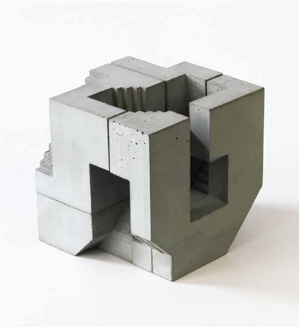
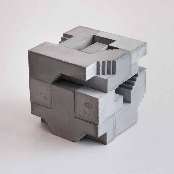
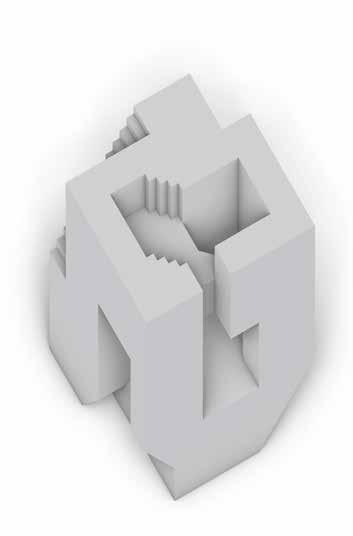
David Umemoto’s D8
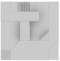
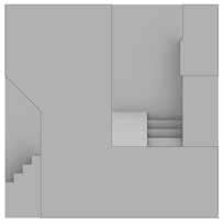
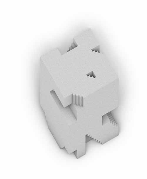
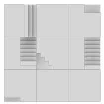
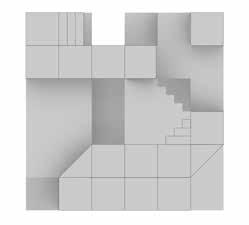
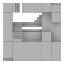
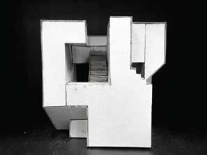
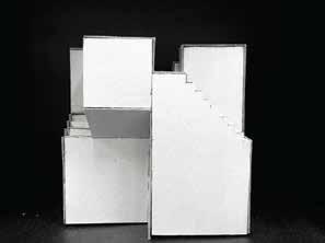
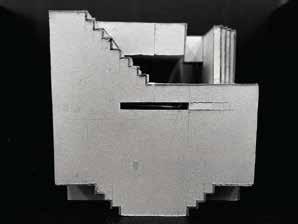
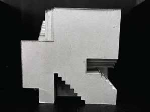
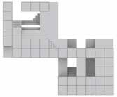
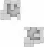
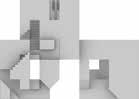
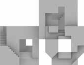
D8 was a fairly straightforward cube to work with. The D8 cube consisted of interfaces which could be used. For example, it came with a terraced top surface to allow for possible use for activities, as well as a lower floor which was still relatively open. The stairs at the side also allowed for the possibility to circulate from other cubes.
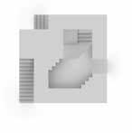
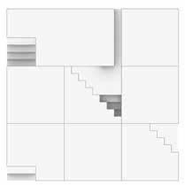
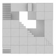
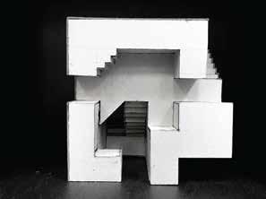
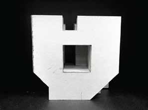
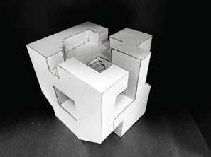
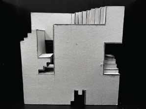
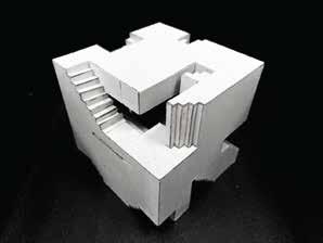
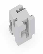
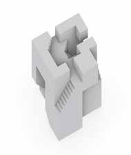
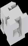
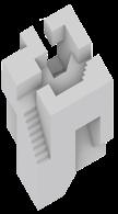
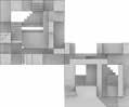
CUBE XS was not as straightforward to work with. In this regard, Cube XS was mainly solid within and had to be opened up. It is formed from 7 different modules, whcih are able to interface with each other in different ways. In my study, I use the interface shown in the image to shape my operated cubes by following the inner tectonics of how the different parts interface with one another. This allowed me to explore various ways on opening up the cube in a manner which followed it’s original tectonics
David Umemoto’s CUBE XS
SCALE: 1:80
DRAWN BY: JONATHAN LAU
AXONOMETRIC PROJECTION
David Umemoto’s
D8
SECTION A-A
SECTION B-B
B B A A
AXONOMETRIC PROJECTION1
SCALE: 1:80
DRAWN
BY:
JONATHAN LAU
David Umemoto’s
SECTION A-A
XS
SECTION B-B
A A B B SOMA CUBE
BLOCK IDEATION & MANIPULATION
D8
SCALE: 1:80
SOMA CUBE
XS
SCALE: 1:80
Direct cut through solids Bore through space
A-A SECTION B-B SECTION A-A SECTION B-B A A B B A A B B
SECTION
LEGEND
OPERATED CUBES
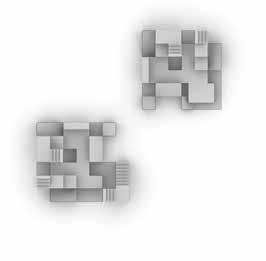
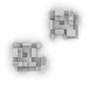
Operated D8
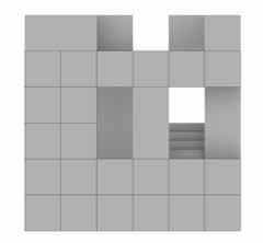
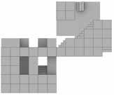
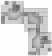
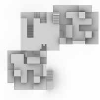
With respect to the pre-existing interfaces within the D8 cube, I decided to open up the cube even more. In this operated cube, various spaces were opened up, such as the stairs, which allowed for external circulation. The back allowed for circulation from the upper and lower floors of the cube as well.
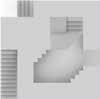
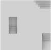
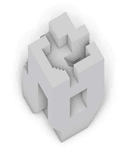
Operated CUBE XS
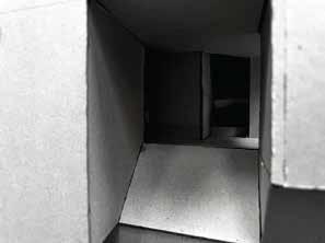
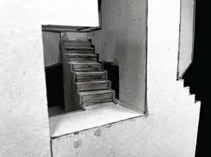
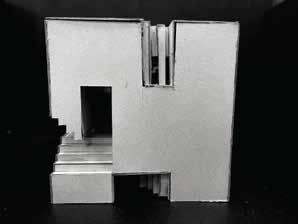
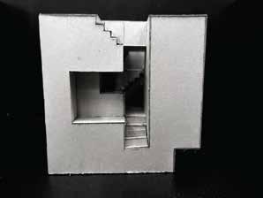
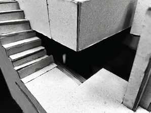
The operated XS demonstrated very interesting features. In this operated cubes, the area was opened up with respect to the tectonics of how the modules interfaced with each other, leading to a central staircase which led from the bottom of the cube to the top. Transitory areas (thresholds) were also identified and used to facilitate the movement between space to space. Openings within the cube also demonstrated useful to create a hierachy of seen and unseen spaces, allowing for some spaces to be seen more than others with a 4-level code which this cube followed.
OP CUBE 1
SCALE: 1:80
DRAWN BY: JONATHAN LAU
AXONOMETRIC PROJECTION
 SECTION A-A
B B A A
SECTION B-B SECTION CUTS
AXONOMETRIC PROJECTION
SECTION CUTS
DRAWN BY: JONATHAN
LAU
2
A A B B
OP CUBE
SCALE: 1:20
SECTION A-A
SECTION B-B
OP CUBE 1 1:50 Model 1 2 3 4 5 6 7 8 1. Front View 2. Right View 3. Back View 4. Left View 5. Top View 6. North-west Perspective 7. View from open area into living space
View of the staircase leading to the common area
8.
1:50 Model 1 2 3 4 5 6 7 8 1. Front View 2. Right View 3. Back View 4. Left View 5. Top View 6. South-east Perspective 7.
right entrance 8.
upper
lower
OP
2
View from
View of the staircase connecting
and
floors
CUBE
combination process
module 1
rotate original cube by 90⁰ anti-clockwise
module 2
module 3
rotate original cube by 90⁰ clockwise
mirror original cube
combination analogue
scale 1:200
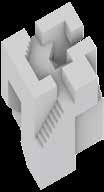
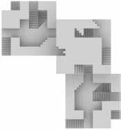
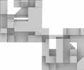
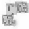
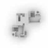
Unit it formed by 3 blocks connected through circulatory nodes. Comprises of 2 D8 operated cubes which act as both the entrance points and end nodes, as well as one XS operator cube which acts as a transitory/ intermediate space. As the XS operated cube is in between the 2 D8 operated cubes, this causes symmetry within the formation of spaces within the dwelling unit.
The units are connected at the circulatory nodes at each cube. The operated XS was used as a threshold space where people can transit through to the next space.
Section A-A Section B-B scale 1:200 sections B B A A
final unit scale 1:200
COMBINED CUBES
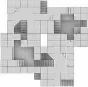
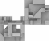
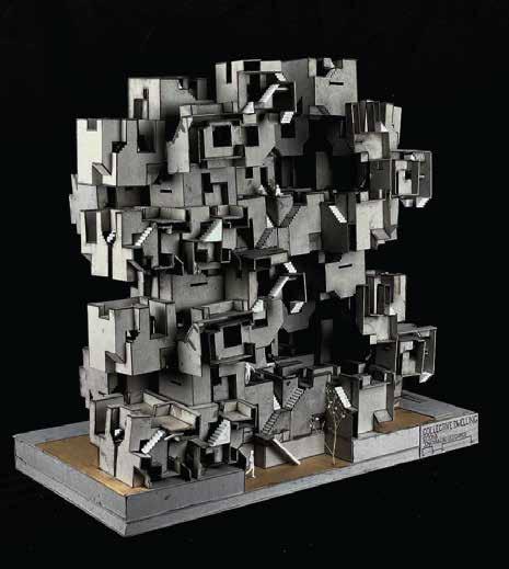
4 Stack (1st & 2nd Iteration)
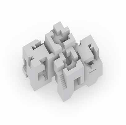
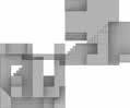
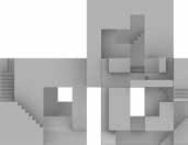
For the first iterations of the cubes, I sought order and complexity in the various designs. In the first iteration, a hierachy of spaces were created to emphasise changes in area condition. These changes were employed by the use of stairs of varying heights. However, the interface of the cubes was overly-complex and the order was somewhat random. Due to the over-complexity of the structure, the spatial order was not very intentional and became too random, hence not being designed in a way which can accomodate to properly to the needs of potential residents.
The second iteration saw a significantly more compact design, where the cubes were interfaced in a square-like structure. This iteration saw better connections between spaces and the movement from big to small through accessibility. However, the non-linear circulatory paths segmented the cube into too many redundant micro-spaces.
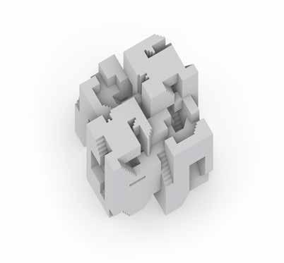
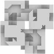
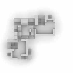
3 Stack (Final Iteration)
This stack derived from the use of 2 D8 operated cubes connected to 1 central XS cube. The XS operated cube acts as a node between the two cubes, as well as the upper floors. The D8 operated cubes are also open on the second storey, allowing for circulation to adjacent cubes.
The two D8 cubes serve different purposes. The bigger D8 accomodates to service spaces, such as the toilets, as well as the kitchen, while the smaller D8 accounts for the private dwelling areas, as well as the sitting/dining areas. The size of the smaller D8 is also due to the fact that it allows for curculation between lower floors and it’s respective unit as well.
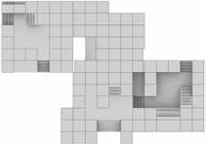
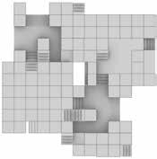
AXONOMETRIC PROJECTION AXONOMETRIC PROJECTION LEVEL 1 PLAN LEVEL 2 PLAN ROOF PLAN A A B B A A B B A A B B
ITERATION 2 SCALE: 1:200 LEVEL 1 PLAN LEVEL 2 PLAN LEVEL 3 PLAN A A B B A A B B A A B B
ITERATION 1 SCALE: 1:200
DWELLING ANALOGUE
SCALE: 1:200
AXONOMETRIC PROJECTION


2nd Floor 3rd Floor 1st Floor Section A-A open/closed spaces seen/unseen spaces Section B-B hierachy of spaces *depends on unit cluster spatial analog 2nd Floor 3rd Floor 1st Floor closed intermediate Legend open unseen partially seen Legend seen private transitory Legend public mixed*
1. Front View 2. Right View 3. Back View 4. Left View 5. Top View 6. North-west Perspective 7. View under XS operated cube into the 2 side windows of the private living space 8. View from the common corridor through the XS operated cube to show central staircase leading to the next floor 1 2 3 4 5 6 7 8 DWELLING ANALOGUE 1:50 Model
COLLECTIVE PROJECTION
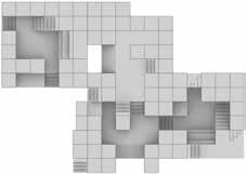
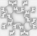
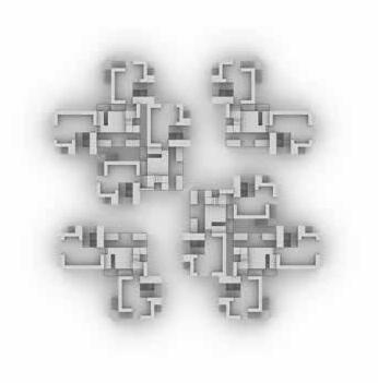
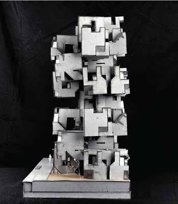
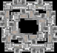
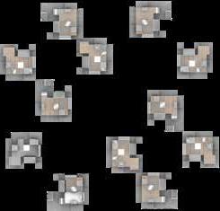
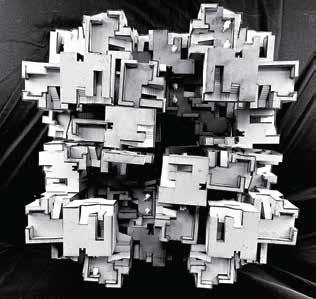
Collective Projection (1st Iteration)
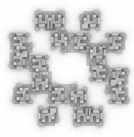
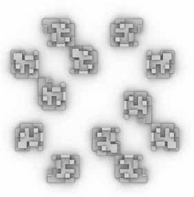
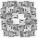
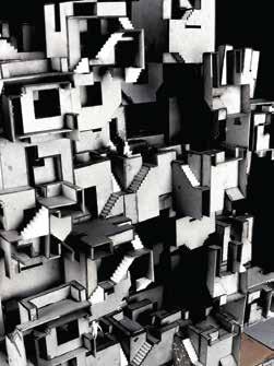
For the first iteration of my collective projection, I was aiming to create an aggreation that was able to manifest two antagonistic personality traits: extroversion and introversion. In the process, a form of duality was created, where the nature of the clusters alternated with each stack. This can be seen on the central pathway in the first cluster, allowing all units to be connected to each other. The terraces on each floor also face each other, allowing neighbours to look directly into each others’ units. This openess makes the units in the first cluster open, where areas are communal in nature.
The second cluster consists of completely disjointed units which do not connect with one another at all within the cluster. The framing of each terrace also faces out, having limited interaction with other units within the same cluster other than a limited section of their adjacent neighbour’s terrace, thus causing the units in this cluster to be relatively more private.
However, the total area of this collective dwelling was only approximately 960sqm, which was significantly less than the requirement. Due to this, I sought a design which could keep a similar analog while increasing the density of this collective.
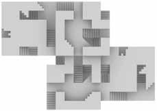
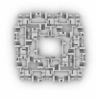
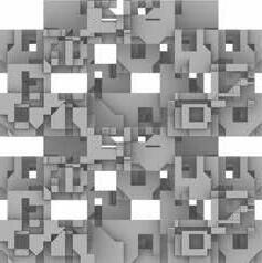
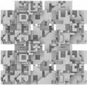
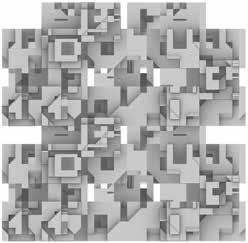
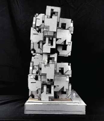
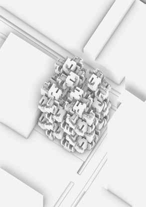
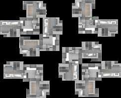
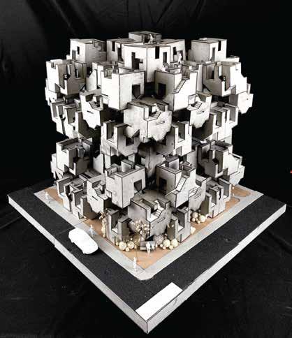
Collective Projection (Final Iteration)
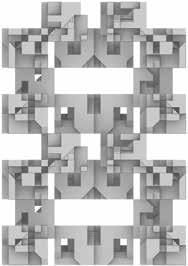
The final iteration saw an increase in density from the original 16 cubes to 32 cubes. This managed to bring the area up to around 1920sqm (not accounting for overlaps). This iteration was able to bring out new traits while keeping the duality of the first iteration. In addition, the final iteration also saw the use of a ‘double ring’ circulatory path on the first cluster. This formed 2 ring-like layers where an inner and outer ring of dwellings were formed and connected through the cubes.
Due to the increased density, circulation to the from cluster 2 to 3 was reduced to the centre 2 dwelling units due to overlaps. These overlaps allow the collective dwelling to have some form of structural integrity.
COLLECTIVE PROJECTION (1ST ITERATION)
SCALE: 1:200
scale 1:400 A A section A-A Cluster 2 Legend Cluster 1 1:100 (641) STATION
INTERIM ACTION PLAN
Feedback and Comments
This feedback gave a greater sense of clarity to the project. Comments were given as such:
1. The cubes have many inherent external staircases which has not been utilised.
2. How can circulation be represented? Will I represent this circulation with the cubes or through an external structure?
3. Cubes need to be combined more intentionally. They are just touching each other and not giving support at the moment. Need to look at how to interface them better.
4. The form of the collective dwelling is generally ok. Explanation of the dwelling analogues and clusters need to be a lot clearer.
5. Manage presentation time more wisely.
Action Plan
With respect to the feedback given, certain actions were listed out for the accountability and expansion of the project:
1. Find a purpose for the serated edges in the cubes. However, intentionality needs to be carried out to prevent cubes from losing their essence and form. Exploration on the different purpose of each edge should be explored.
2. Apply and fall back on the matrix if possible. In this case, Repeated seen/unseen and accessibility.
3. Circulation needs to be developed. Designation of spaces and the various nodes need to be identified, as well as the pathways to get to these different spaces.
4. Building tectonics need to be adjusted. This would add to the structural integrity of the collective dwelling.
5. More sense needs to be made to the proportions of the individual cubes. This would ensure their habitability. Configuration of both the individual cubes, as well as the tectonics of the overall structure may have a role to play in this as well
ROAD)
SITE STUDY >
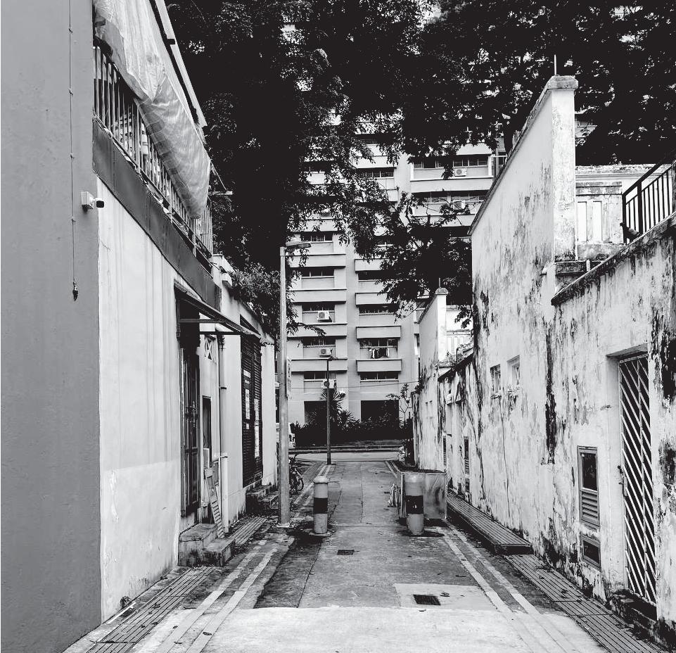
> Back Alley (Baboo Ln)
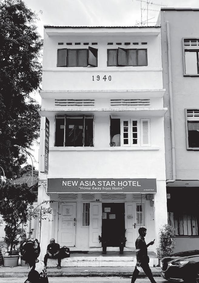
New Asia Star Hotel (Rowell Rd)
SITE STUDY
Site Mapping
A Nolli map was used to map the site to understand the various hidden voids within where public circulation was made available. This would allow the dwelling to somewhat follow a similar analog.
A supplementary diagram illustrating the various programs, circulatory paths and features of the site allows certain traits of the site to be observed, such as the way green buffers and planters were used to control human circulation.
Site Condition Study
In this site, I found two areas to be quite interesting. These areas are the front and back of New Asia Star Hotel. While comparing how both areas orchestrated the movement of people, I found both these areas to be antagonistic to each other, where one invited and enticed circulation and the other blocked and filtered it. The front of the hotel employed the use of gruadual height change to give spatial order and hierachy to the openess of the space, creating an inviting entrance. The back end used barriers and had an enclosed alleyway, creating an area which was rather unwelcoming in comparison to the front.
Site Engagement
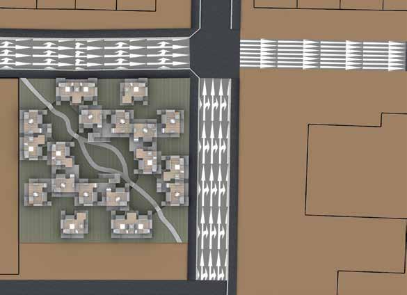
In the process of deciding how the building should be placed on the site, I kept the current circulatory path in consideration. Taking into account that the current area is allocated as the ‘Rowell Road Green Corner’, I envisioned for the site to continue serving the purpose of being a green space for not just residents, but for passers by.
Aside from considering the footprint of the building, I also considered the condition of the inherent buildings in the area, especially the HDB block on the opposite side of Kampong Kapor Road. In the current site, a tree currently stands to provide shade to the block till about level 10. My aim for this project is not to plainly design a building to replace the tree, but create something which is able to continue giving the same effect as the tree, while remaining relevant to it’s purpose.
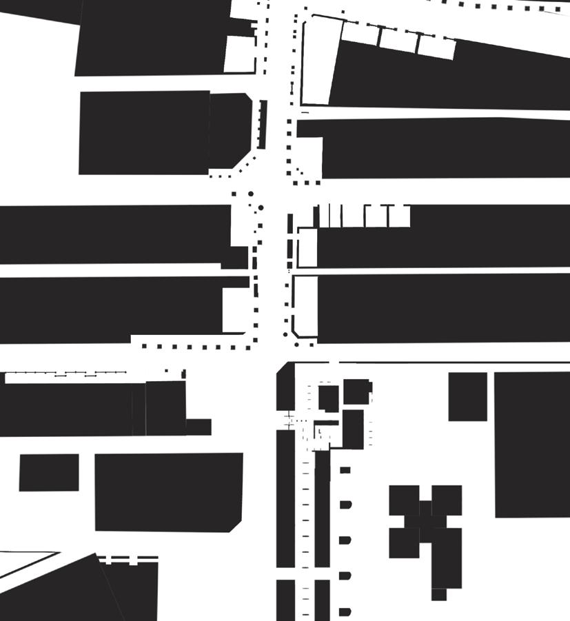
NOLLI MAP
Scale 1:1000
The use of the Nolli Map allows up to clearly see the various public pathways around the site. It allows us to note which points in the site are both accessible and those that are not to public use.
This allows us to understand accessibility within the site to understand both accessible spaces, as well as seen and unseen spaces within the site.
site
DISTRUPTION OF ACCESSIBILITY <
TRANSLATION
The 3 Sections below illustrate the height movements from the common areas to private spaces within a dwelling, as well as the openess of the spaces.
For the transition within public open areas to the threshold block (Cube XS), a small step illustrates the change of spatial condition. From this step, individuals can either choose to:
1. Stay in the threshold area, where they take a single step down to block’s central area
2. Move to the adjacent block(s), where they would have to go through the central area of the blocks
3. Go to the next floor via the staircase, which leads to an open space at the top of the cube.
For movements into private spaces, individuals need to walk down a flight into the individual units. This flight acts similarly to the barrier where it shows a clearer distinction in between spaces.

SPATIAL HIERACHY
USE OF HEIGHTS AND LIGHT TO ORDER SPACES
TRANSLATION
The sections on the left emulate how light enters the spaces at different sections, as well as how open or closed the spaces are. Spaces are designed similarly to the condition where more public spaces are open and more light is allowed to enter these spaces.
The living spaces are significantly more closed up compared to the rest of the unit. The diagrams illustrate that the living spaces also do not get as much direct sunlight as the other areas, however have openings which provide ambient light during the day.


SECTION B use this man. the others are all taller than 2m in height SECTION A SECTION C BABOO LANE PLAN VIEW POWER STATION SITE (OPEN SPACE) INN VACANT SLA PROPERTY SLA PROPERTY SLA PROPERTY A B C A B C
USE OF ALLEYWAYS TO CREATE TRESHOLDS
FRONT ELEVATION POCHE (OPAQUE) SECTION CUT 1 2 5 3 4 SECTION A Scale: 1:100 SECTION B SECTION C 1 3 2 1 3 2 SECTION A SECTION B SECTION C SECTION D 1 1 2 2 5 3 1 3 4
>


SECTION PROJECTIONS (STANDARD UNIT)
1:200 ROOF PLAN LEVEL 1 PLAN LEVEL 2 PLAN SECTION B SECTION A SECTION C SECTION D B C D A B C D A FLOOR PLANS (STANDARD UNIT) SCALE 1:200 5 1 3 4 4 2 LEGEND PRIVATE LIVING SPACE PRIVATE THRESHOLD (MULTI-PURPOSE) COMMON SITTING/ DINING AREA PUBLIC THRESHOLD CIRCULATION TO UPPER FLOORS LEGEND LIVING SPACE PRIVATE THRESHOLD AREA SITTING/ DINING AREA CIRCULATION TO LOWER FLOORS PUBLIC THRESHOLD STORAGE SPACE FOR UNIT CIRCULATION TO UPPER FLOORS LEGEND CIRCULATION FROM LOWER FLOORS PUBLIC CIRCULATORY CORRIDOR/ SITTING AREA PRIVATE THRESHOLD AREA (MULTI-PURPOSE) PUBLIC THRESHOLD STORAGE SPACE FOR UNIT OPEN KITCHEN PRIVATE TRESHOLD 8 SHOWER 9 WC (TOILET AND SINK) 5 6 7 1 3 4 2 5 6 7 1 3 4 2 LEGEND CIRCULATION FROM LOWER FLOORS PUBLIC CIRCULATORY CORRIDOR/ SITTING AREA PRIVATE THRESHOLD AREA (MULTI-PURPOSE) PUBLIC THRESHOLD STORAGE SPACE FOR UNIT OPEN KITCHEN PRIVATE TRESHOLD 5 6 7 1 3 4 2 1 2 5 8 9 3 5 6 7 1 3 4 2 5 6 7 1 3 4 5 6 4 2 1 3 2 7 3 1 3 3 4 5 5 6 8 2 1 1 7 7 1 3 4 2 2 2 2 2 COLOUR LEGEND CIRCULATION DWELLING COMMON AREA DWELLING QUATERS NEXT UNIT DWELLING INTIMATE SPACES 1 3 4 2 LEGEND BATHROOM PRIVATE THRESHOLD (MULTI-PURPOSE) CIRCULATION TO COMMON AREA BEDROOM 5 6 8 7 1 3 4 2 LEGEND OPEN KITCHEN PUBLIC CIRCULATORY CORRIDOR CIRCULATION TO PRIVATE SPACE PUBLIC THRESHOLD CIRCULATION TO UPPER FLOORS STORAGE SPACE FOR UNIT DINING/ SITTING AREA CIRCULATION TO LOWER FLOORS 1 2 LEGEND CIRCULATION TO NEXT FLOORS UPPER FLOOR UNIT COLOUR LEGEND CIRCULATION DWELLING COMMON AREA DWELLING QUATERS NEXT UNIT DWELLING INTIMATE SPACES
SCALE

CLUSTER 1 PLAN CLUSTER 2 PLAN SCALE 1:400 SCALE 1:400 LEVEL 1 (DWELLING) LEVEL 1 (DWELLING) LEVEL 2 (COMMON AREAS) LEVEL 2 (COMMON AREAS) LEGEND ENTRANCES/ CIRCULATION FROM LOWER FLOORS NEXT FLOOR ROOF/ NO ACCESS TO NEXT FLOOR PRIVATE LIVING SPACES E P N R COMMON AREAS C CENTRAL GARDEN G SECTION A SECTION B B B A A SCALE 1:400 SPATIAL DISTRIBUTION SPATIAL DISTRIBUTION SCALE 1:400 LEGEND PUBLIC THRESHOLDS PUBIC CIRCULATION PUBLIC COMMON AREAS PRIVATE THRESHOLDS PRIVATE CIRCULATION PRIVATE LIVING SPACES P P P P C C C E E P P P P P P P P R R R E E E P P P N LEVEL 1 PLAN (GROUND FLOOR) P P P C C C C C C C P P P C C C
1 2 6 7 8 9 10 11 12 13 3 5 4 1.
2.
3.
4.
5.
6.
Front of section model
Left of section model
Back of section model
Right of section model
Top of section model
South-West projection of section model
7.
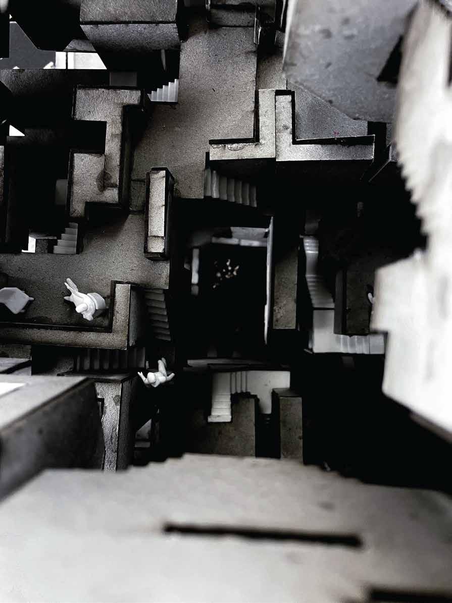
Close-up 1: quality of spaces in the aggregation
8.
Close-up 2: quality of space from 1st floor
9.
Site Axonometric projection 10. Rendered view from Rowell Road
11.
Rendered interior from Cluster 3 terraces/coridoor 12. Rendered view from XS operated cube to common coridoor (cluster 1) 13. Rendered interior from Cluster 2 terraces
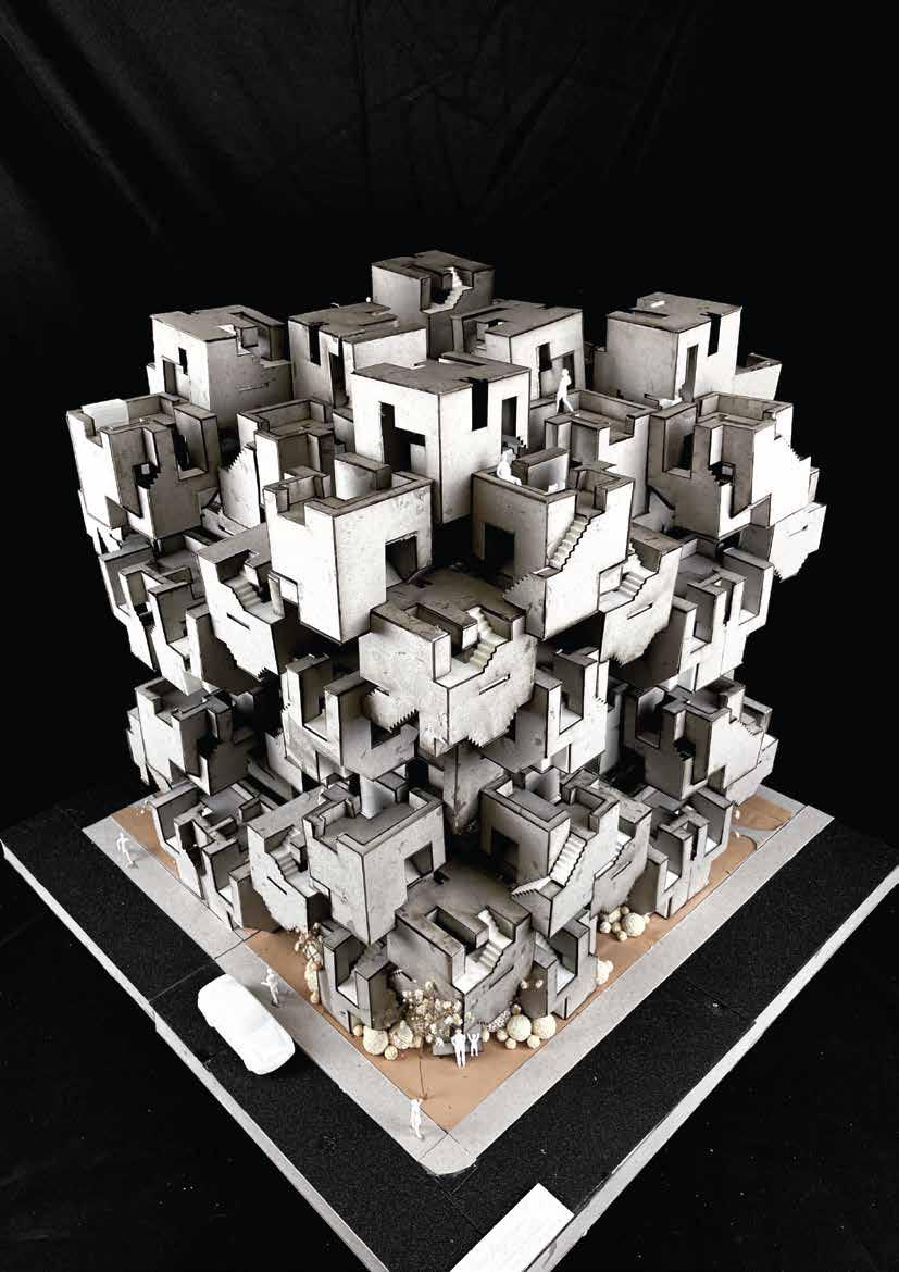
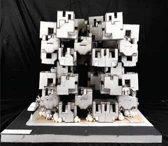
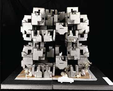
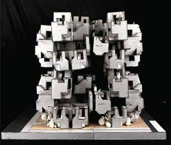
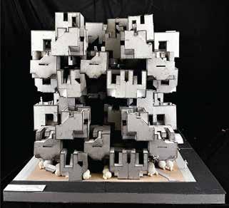
FINAL MODEL
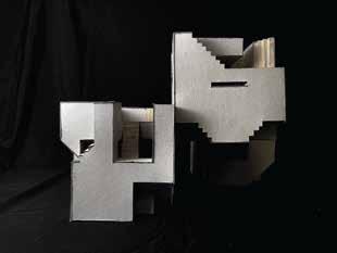
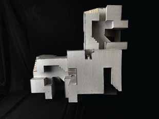
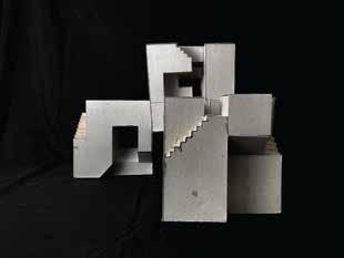
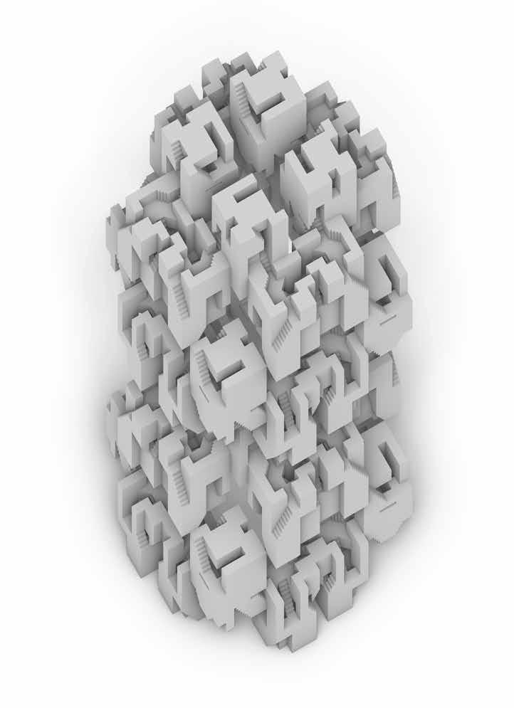
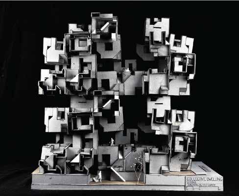
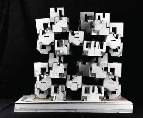
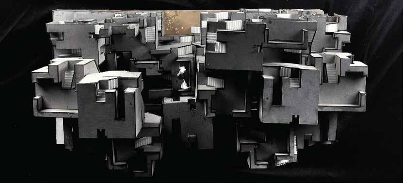
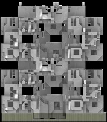
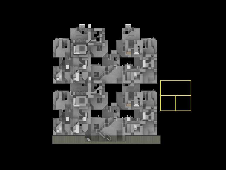
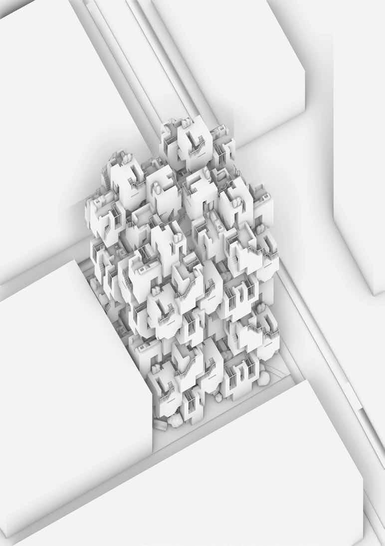
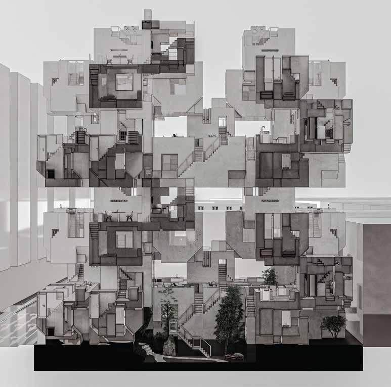
Overview
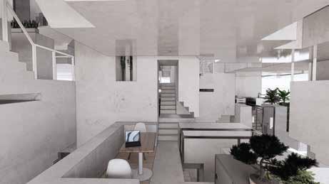
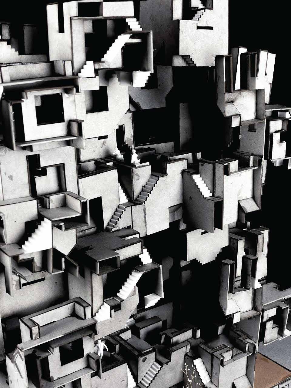
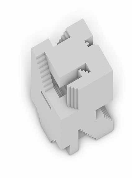
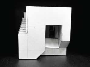
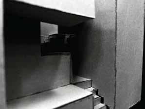
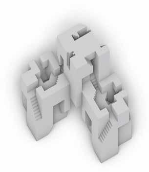
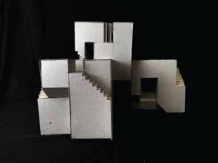
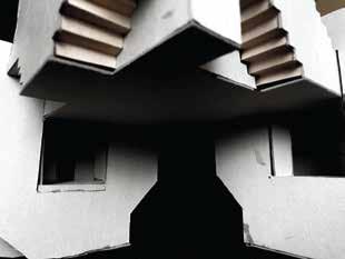
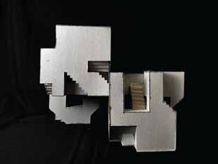
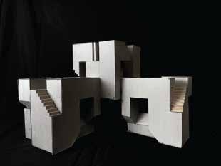
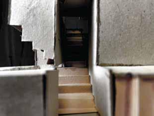
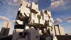
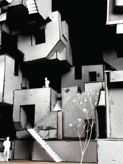
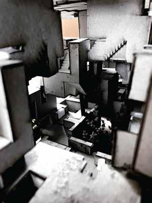
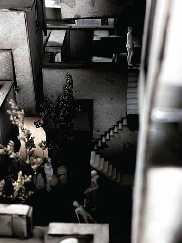
In the final model, I wanted to continue to show the sense of spatial quality through the movement between spaces. The final model, which opened up into 2 sections, aims to illustrate how the two sides complement each other. This model also depics the central void, where 2 fully open voids can be observed. One of these fully open spaces can be seen in the image on the previous page.
Similarly to the previous cross sectional model, the final model aims to illustrate how people are able to interact within the dwelling as a whole. It aims to illustrate how the spatial quality would affect how people may percieve the different spaces and utilise them.
Unlike the previous model, where the bottom of each cube was not an emphasis, this model aims to illustrate how these bases, which acts as the height clearance for the previous floor, interacts with the spaces below it. This aims to show how the placement of the blocks may define the spatial quality of spaces below them.
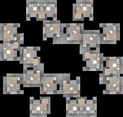
Finally, this model also aims to give a bit of site context, where a small section of the adjacent roads are shown, as well as the pavement. These exteral elements wold illustrate briefly how the building would interact with the site. This would also show how the different external spaces would interact and how planters are used to conceal the living spaces of residents dwelling in the first cluster by creating a green barrier between the units and the pavement.


SECTION B SECTION C SCALE 1:266 SCALE 1:266 SECTIONAL ACTIVITIES SECTIONAL ACTIVITIES LEGEND (SECTIONAL ACTIVITIES) PUBLIC THRESHOLDS PUBIC CIRCULATION PUBLIC COMMON AREAS PRIVATE THRESHOLDS PRIVATE CIRCULATION PRIVATE LIVING SPACES BLK 641 KAMPONG KAPOR ROAD COLLECTIVE DWELLING
COLLECTIVE DWELLING
ROWELL ROAD
NEW ASIA STAR HOTEL
BABOO LANE SHOPHOUSES
1
CLUSTER 2 PLAN
SCALE 1:400
E P P P P P P P P R R R
STOREY
7 (DWELLING)
CLUSTER
PLAN SCALE 1:400 STOREY 5 (DWELLING)
3,
E C C C C C P P C STOREY 2, 6 (COMMON AREAS) *The final cluster would not circulate to the next floor, but to the roof LEGEND ENTRANCES/ CIRCULATION FROM LOWER FLOORS NEXT FLOOR ROOF/ NO ACCESS TO NEXT FLOOR PRIVATE LIVING SPACES E P N R COMMON AREAS C CENTRAL GARDEN G STOREY 4, 8 (COMMON AREAS) P P P C P P C P P C E E E E E P P P P N* R R ROWELL ROAD
BABOO LANE N E P C P P P P P P P P C C C C C P C C P P P P C C N G ROWELL ROAD ROWELL ROAD STOREY 1 (DWELLING) KAMPONG KAPOR ROAD PEDESTRIAN ACCESS BARRIERS
GROUND FLOOR PLAN SCALE 1:400
ROWELLROAD
AXONOMETRIC PROJECTION SCALE 1:150
BABOOLANE
KAMPONG KAPOR ROAD


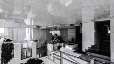
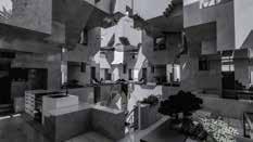
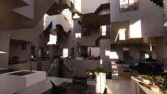
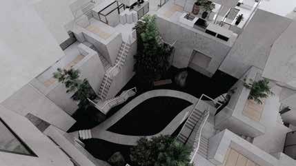
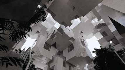
View A illustrates the range of perception from one of the cluster 2 dwellings. These dwellings are relatively more exclusive compared to the first cluster. The circulation for each dwelling unit is separate from each other. In addition, the viewing range of each unit, as depicted, allows residents to only look into a part of their neighbour’s units, giving the residents significantly more privacy from their neighbours. View B, on the other hand, is from the inner circulation ring on the third cluster dwellings. The spaces are comparatively more interconnected and are able to lead to each other, utilising a double loop circulation to allow interconnectivity among the 10 dwelling units. The middle area also features an open void which allows natural light to enter the dwelling. This void also emphasises the expansion of spaces from the various enclosed spaces in the cubes. View C features a worm’s eye perspective from the garden of the dwelling. This image illustrates the open central courtyard, where the height is high enough to allow for larger planters, such as trees to be grown. This open spatial quality also complements the architectural experience when walking into the collective dwelling. The movement from an open area into a closed area, and back into a large open space gives individuas transiting through the spaces informs him/her that they have transited into a new space. SECTION C PERSPECTIVE 3D VIEWS SCALE 1:150 A A B B C C
Model Faces
 Front View
Left View
Right View Back View
Rowell Road
Kampong Kapor Road
New Asia Star Hotel Baboo Lane
Front View
Left View
Right View Back View
Rowell Road
Kampong Kapor Road
New Asia Star Hotel Baboo Lane
1 2 3 4 1. Top view of dwellng 2. West-facing building angle 3. View from top of cluster 1 into terraces 4. View from top of cluster 1 into the garden Model Spaces & Overview
2 3 4
1. Two point perspective facing true west direction.
2. View of garden from 2nd cluster (level 4)
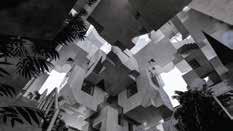
3. Worms’ eye perspective from garden up. 4. Central void observed from the 3rd cluster (level 6)
1
3D Views
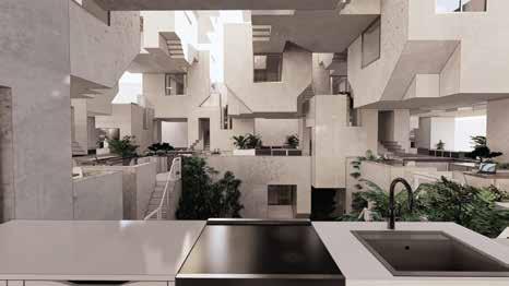
This view is taken from the perspective of someone moving through the outer loop of the first cluster from the node operated cube.
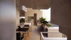
The use of these nodal cubes create a threshold, where people can understand that as they pass through one, they are entering a different space. This can be observed where the space transits from a more closed one in the transitory space, to a larger one (in this cae the kitchen)
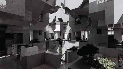
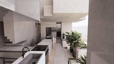
This view is taken from the perspective from one of the kitchens in the inner loop in the first cluster, whch looks into the open void.
This void createsthe impression that the collective terrace areas within this cluster are not separate spaces, but one singular space. This creates an environment which is more communal in nature.
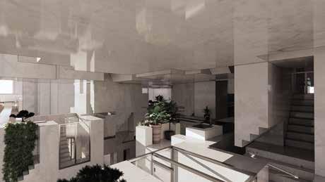
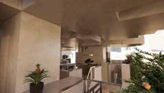
This view is taken from the perspective of someone from the living spaces in one of the units from the second cluster into the treshold cube.
This space, although not fully closed, is more closed in comparison to the same space in a unit in cluster 1. This illustrates how the different spaces, The distance and disconnectivity from neighbours also complements the exclusive nature of this cluster.
This view is taken from the perspective from one of the kitchens in the second cluster.
Due to the exclusive nature of this cluster, residents not only have less neighbours, but, the cubes also only allow them to look into the terrace of their adjacent neighbours.