
C C H H A A P P T T E E R R 6 6
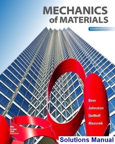
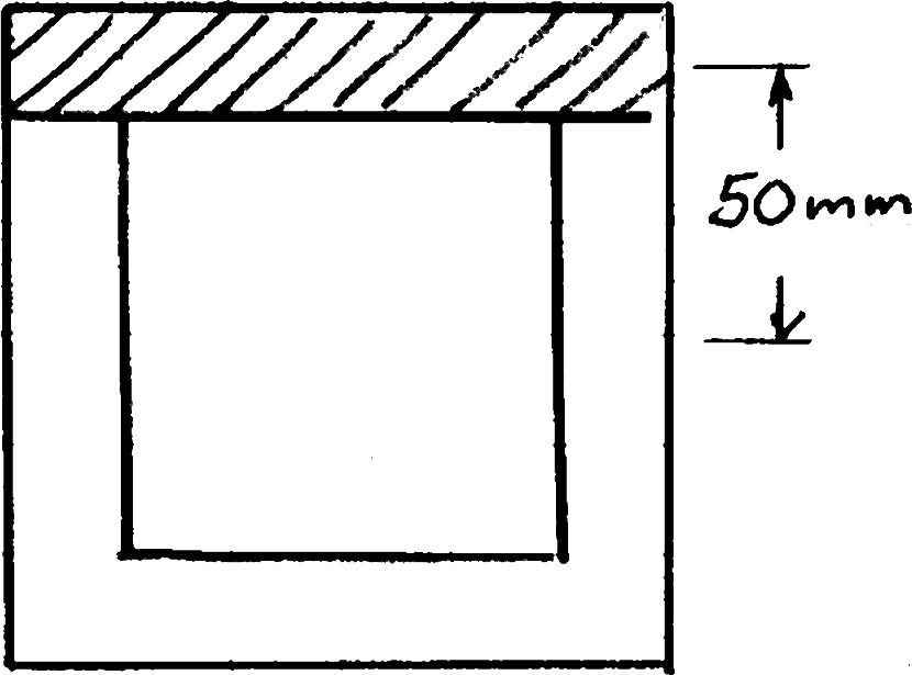
PROBLEM 6.1
s
50 mm
50 mm 100 mm
SOLUTION 113364 (100)(150)28.12510mm 1212 I bh 28.12510m64 2 (100)(50)5000mm A 1 50mm y 3363 1 25010mm25010mQAy 6 3 6 (1500)(25010) 13.333310N/m 28.12510 VQ q I nail 2 qsF 3 nail 3 2(2)(400) 60.010 m 13.333310 F s q 60.0mm s
PROPRIETARY MATERIAL. Copyright © 2015 McGraw-Hill Education. This is proprietary material solely for authorized instructor use. Not authorized for sale or distribution in any manner. This document may not be copied, scanned, duplicated, forwarded, distributed, or posted on a website, in whole or part.
893
s s
50 mm
50 mm
50 mm
100 mm
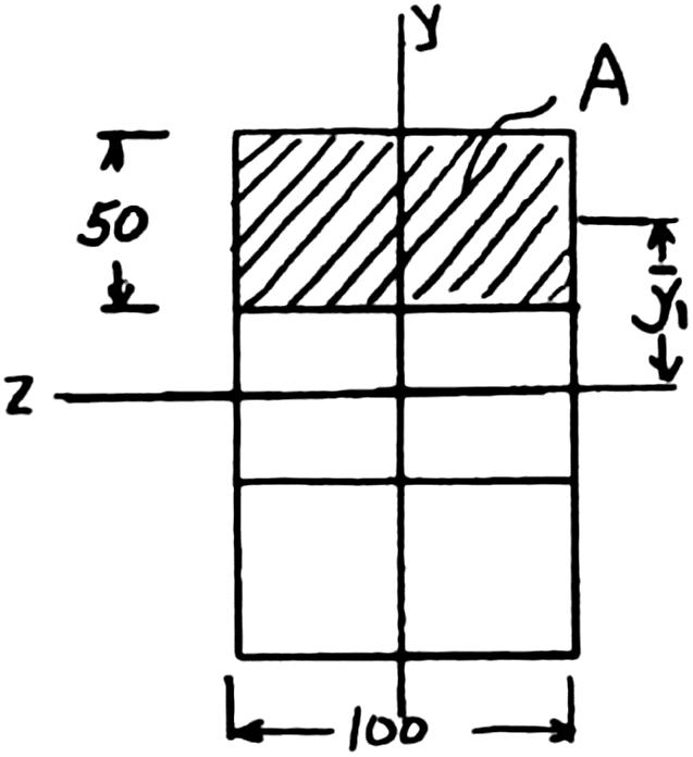
PROBLEM 6.2
For the built-up beam of Prob. 6.1, determine the allowable shear if the spacing between each pair of nails is s 45 mm.
PROBLEM 6.1 Three full-size 50 100-mm boards are nailed together to form a beam that is subjected to a vertical shear of 1500 N. Knowing that the allowable shearing force in each nail is 400 N, determine the largest longitudinal spacing s that can be used between each pair of nails.
SOLUTION
I bh
113364 (100)(150)28.12510mm 1212
28.12510m64
A
2 (100)(50)5000mm
1 50mm
3363 1 25010mm25010m
Eliminating ,q nail 2 VQF I
Solving for V,
3 nail 63 2(2)(28.12510)(400) 2.0010N (25010)(4510)
PROPRIETARY MATERIAL. Copyright © 2015 McGraw-Hill Education. This is proprietary material solely for authorized instructor use. Not authorized for sale or distribution in any manner. This document may not be copied, scanned, duplicated, forwarded, distributed, or posted on a website, in whole or part.
894
PROBLEM 6.3
Three boards, each 2 in. thick, are nailed together to form a beam that is subjected to a vertical shear. Knowing that the allowable shearing force in each nail is 150 lb, determine the allowable shear if the spacing s between the nails is 3 in.
PROPRIETARY MATERIAL. Copyright © 2015 McGraw-Hill Education. This is proprietary material solely for authorized instructor use. Not authorized for sale or distribution in any manner. This document may not be copied, scanned, duplicated, forwarded, distributed, or posted on a website, in whole or part.
s s s
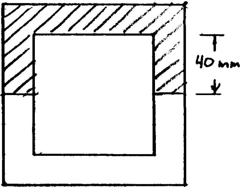
20 mm
80 mm
20 mm
(
120 mm
PROBLEM 6.4
A square box beam is made of two 2080-mm planks and two 20120-mm planks nailed together as shown. Knowing that the spacing between the nails is 30 s mm and that the vertical shear in the beam is 1200 N, V determine (a) the shearing force in each nail, (b) the maximum shearing stress in the beam.
PROPRIETARY MATERIAL. Copyright © 2015 McGraw-Hill Education. This is proprietary material solely for authorized instructor use. Not authorized for sale or distribution in any manner. This document may not be copied, scanned, duplicated, forwarded, distributed, or posted on a website, in whole or part.
896
S310
16
PROBLEM 6.5
The American Standard rolled-steel beam shown has been reinforced by attaching to it two 16200-mm plates, using 18-mm-diameter bolts spaced longitudinally every 120 mm. Knowing that the average allowable shearing stress in the bolts is 90 MPa, determine the largest permissible vertical shearing force. SOLUTION
Calculate moment of inertia:
PROPRIETARY MATERIAL. Copyright © 2015 McGraw-Hill Education. This is proprietary material solely for authorized instructor use. Not authorized for sale or distribution in any manner. This document may not be copied, scanned, duplicated, forwarded, distributed, or posted on a website, in whole or part. 897
C12
PROBLEM 6.6
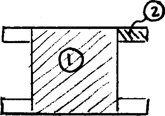
The beam shown is fabricated by connecting two channel shapes and two plates, using bolts of 3 4 -in. diameter spaced longitudinally every 7.5 in. Determine the average shearing stress in the bolts caused by a shearing force of 25 kips parallel to the y axis.
PROPRIETARY MATERIAL. Copyright © 2015 McGraw-Hill Education. This is proprietary material solely for authorized instructor use. Not authorized for sale or distribution in any manner. This document may not be copied, scanned, duplicated, forwarded, distributed, or posted on a website, in whole or part. 898
PROBLEM 6.7
A columm is fabricated by connecting the rolled-steel members shown by bolts of 3 4 -in. diameter spaced longitudinally every 5 in. Determine the average shearing stress in the bolts caused by a shearing force of 30 kips parallel to the y axis
Geometry:
Determine moment of inertia.
PROPRIETARY MATERIAL. Copyright © 2015 McGraw-Hill Education. This is proprietary material solely for authorized instructor use. Not authorized for sale or distribution in any manner. This document may not be copied, scanned, duplicated, forwarded, distributed, or posted on a website, in whole or part.
PROBLEM 6.8
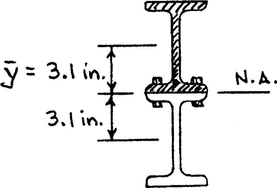
The composite beam shown is fabricated by connecting two W620 rolled-steel members, using bolts of 5 8 -in. diameter spaced longitudinally every 6 in. Knowing that the average allowable shearing stress in the bolts is 10.5 ksi, determine the largest allowable vertical shear in the beam.
PROPRIETARY MATERIAL. Copyright © 2015 McGraw-Hill Education. This is proprietary material solely for authorized instructor use. Not authorized for sale or distribution in any manner. This document may not be copied, scanned, duplicated, forwarded, distributed, or posted on a website, in whole or part.
900
PROBLEM 6.9
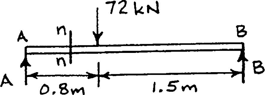
For the beam and loading shown, consider section n-n and determine (a) the largest shearing stress in that section, (b) the shearing stress at point a
At
PROPRIETARY MATERIAL. Copyright © 2015 McGraw-Hill Education. This is proprietary material solely for authorized instructor use. Not authorized for sale or distribution in any manner. This document may not be copied, scanned, duplicated, forwarded, distributed, or posted on a website, in whole or part.
PROBLEM 6.10
For the beam and loading shown, consider section n-n and determine (a) the largest shearing stress in that section, (b) the shearing stress at point a.
PROPRIETARY MATERIAL. Copyright © 2015 McGraw-Hill Education. This is proprietary material solely for authorized instructor use. Not authorized for sale or distribution in any manner. This document may not be copied, scanned, duplicated, forwarded, distributed, or posted on a website, in whole or part.
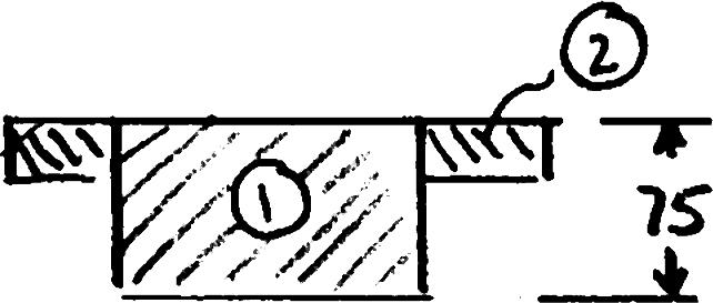
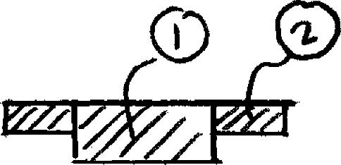
PROBLEM 6.11
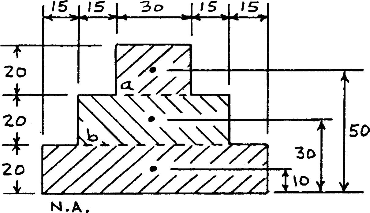
For the beam and loading shown, consider section n-n and determine (a) the largest shearing stress in that section, (b) the shearing stress at point a
SOLUTION
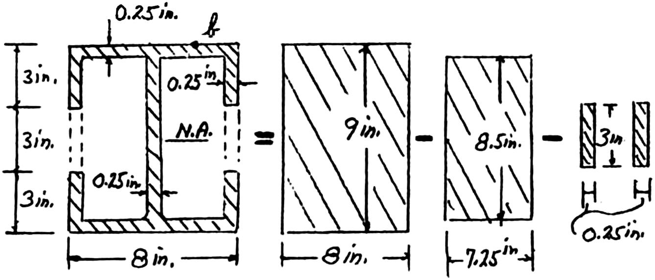
112333 (8in.)(9in.)(7.25in.)(8.5in.)(0.25in.)(3in.)
121212 I
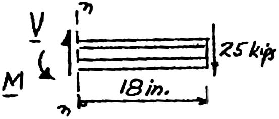
4 113.8in I = 25 kips V (25 kips)(18 in.) = 450 kipin M (a)
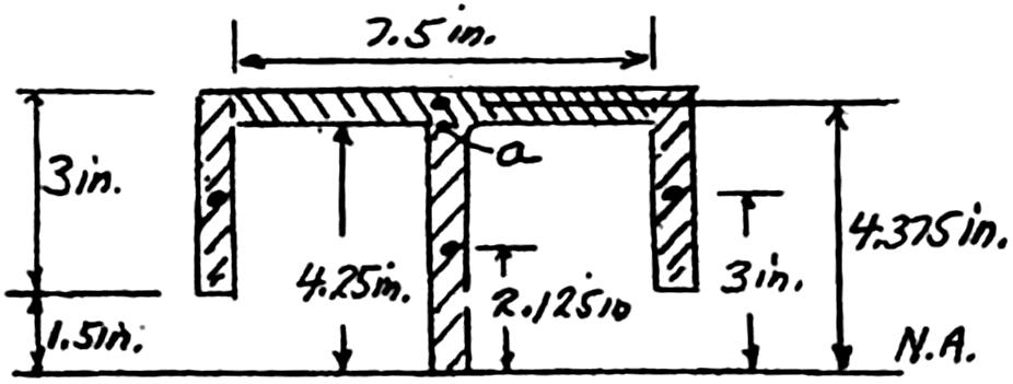
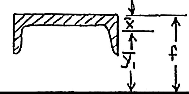
: At neutral axis, thickness 0.25 in 2(3 in.0.25 in.)(3 in.)(7.5 in.)(0.25 in.)(4.375 in.)(4.25 in.)(0.25 in.)(2.125 in.)
3333 4.5 in8.203 in2.258 in14.96 in 0.25 in.
(25kips)(14.96in) (113.8in)(0.25in.)
PROPRIETARY MATERIAL. Copyright © 2015 McGraw-Hill Education. This is proprietary material solely for authorized instructor use. Not authorized for sale or distribution in any manner. This document may not be copied, scanned, duplicated, forwarded, distributed, or posted on a website, in whole or part. 903
(b)
PROBLEM 6.11 (Continued)
a: At point a, = 0.25 in. t See sketch above.
333 4.5 in8.203 in12.70 in Qa
a a VQ It
3 4 (25kips)(12.70in) (113.8in)(0.25in.)
11.16ksi a ◄
PROPRIETARY MATERIAL. Copyright © 2015 McGraw-Hill Education. This is proprietary material solely for authorized instructor use. Not authorized for sale or distribution in any manner. This document may not be copied, scanned, duplicated, forwarded, distributed, or posted on a website, in whole or part.
904