DIFFRACTION DIFFRACTION JESUS PEREZ-CORTEZ BYRON HO
JESUS J. PEREZ-CORTEZ Architecture Portfolio

Omaha, NE 68108 | 4029834754 | jesusperez123.jc@gmail.com | WWW: Bold Profile
Omaha, NE 68108 | 4029834754 | jesusperez123.jc@gmail.com
Omaha, NE 68108 | 4029834754 | jesusperez123.jc@gmail.com | WWW: Bold Profile
Professional Summary
Professional Summary
Professional Summary
Professional Summary
Detail-oriented team player with strong organizational skills. Ability to handle multiple projects simultaneously with a high degree of accuracy.
Detail-oriented team player with strong organizational skills. Ability to handle multiple projects simultaneously with a high degree of accuracy.
Detail-oriented team player with strong organizational skills. Ability to handle multiple projects simultaneously with a high degree accuracy.
Detail-oriented team player with strong organizational skills. Ability to handle multiple projects simultaneously with a high degree of accuracy.
Languages
Languages
Languages
English
Languages
English Spanish Skills
English Spanish Skills
Spanish
English Spanish Skills
Skills
Architecture and Design
Architecture and Design
Architecture and Design
3D Modeling and Visualization
Architecture and Design
Design Research and Development
Design Research and Development
Construction materials
Construction materials
Team Collaboration
Construction materials
Design Research and Development 3D Modeling and Visualization
3D Modeling and Visualization
Construction Documentation
Concept Development
Design Research and Development 3D Modeling and Visualization
Team Collaboration Construction documentation
Team Collaboration
Software
Software
Software
Team Collaboration
Software
Construction documentation
Construction documentation
Adobe Creative Suite | Rhinoceros 3D | Lumion | Enscape | AutoCad | Grasshopper
Adobe Suite | Rhinoceros 3D | Lumion | Enscape | AutoCad | Grasshopper
Adobe Suite | Rhinoceros 3D | Lumion | Enscape | AutoCad | Grasshopper
Adobe Suite | Rhinoceros 3D | Lumion | Enscape | AutoCad | Grasshopper
Work History
Work History
Work History
Architectural Designer - 2 yrs 3 mos
Work History
Architectural Designer - 2 yrs 3 mos
Architectural Designer - 2 yrs 3 mos
Consultant - Omaha, NE
01/2022 - Current
Architectural Designer - 2 yrs 3 mos
Consultant - Omaha, NE
Collaborated with multidisciplinary teams to create functional, efficient, and visually appealing spaces for clients.
Consultant - Omaha, NE
Collaborated with multidisciplinary teams to create functional, efficient, and visually appealing spaces for clients.
Increased client satisfaction by consistently delivering high-quality designs that met or exceeded expectations.
01/2022 - Current
Consultant - Omaha, NE 01/2022
01/2022 - Current
Collaborated with multidisciplinary teams to create functional, efficient, and visually appealing spaces for clients.
Developed comprehensive construction documents to ensure accurate execution of architectural concepts during the building process.
Increased client satisfaction by consistently delivering high-quality designs that met or exceeded expectations.
Developed comprehensive construction documents to ensure accurate execution of architectural concepts during the building process.
Increased client satisfaction by consistently delivering high-quality designs that met or exceeded expectations.
Collaborated with multidisciplinary teams to create functional, efficient, and visually appealing spaces for clients. Increased client satisfaction by consistently delivering high-quality designs that met or exceeded expectations. Developed comprehensive construction documents to ensure accurate execution of architectural concepts during the building
Huntel Engineering - 1 yr 1 mo
Developed comprehensive construction documents to ensure accurate execution of architectural concepts during the building process.
Huntel Engineering - 1 yr 1 mo
Civil Planning Drafter - Blair, NE
Huntel Engineering - 1 yr 1 mo
03/2023 - Current
Huntel Engineering - 1 yr 1 mo
Civil Planning Drafter - Blair, NE
Collaborated with engineers to develop accurate and detailed construction documents for 7 projects.
Civil Planning Drafter - Blair, NE
Collaborated with engineers to develop accurate and detailed construction documents for 7 projects.
03/2023 - Current
Civil Planning Drafter - Blair, NE 03/2023
Collaborated with engineers to develop accurate and detailed construction documents for 7 projects.
Collaborated with engineers to develop accurate and detailed construction documents for 7 projects.
Contributed in reducing errors during before and after construction phase by meticulously reviewing drawings for consistency and accuracy.
03/2023 - Current
Contributed in reducing errors during before and after construction phase by meticulously reviewing drawings for consistency and accuracy.
Evaluated information provided by engineers to create accurate drawings according to measurements and specifications.
Contributed in reducing errors during before and after construction phase by meticulously reviewing drawings for consistency accuracy.
Evaluated information provided by engineers to create accurate drawings according to measurements and specifications.
Contributed in reducing errors during before and after construction phase by meticulously reviewing drawings for consistency and accuracy.
Evaluated information provided by engineers to create accurate drawings according to measurements and specifications.
Hensel Richards Constructors - 4 yrs 2 mos
Evaluated information provided by engineers to create accurate drawings according to measurements and specifications.
Exterior Plasterer - Omaha, NE
Hensel Richards Constructors - 4 yrs 2 mos
Hensel Richards Constructors - 4 yrs 2 mos
05/2017 - 07/2021
Increased client satisfaction with exceptional attention to detail and adherence to design specifications.
Exterior Plasterer - Omaha, NE
Hensel Richards Constructors - 4 yrs 2 mos
Exterior Plasterer - Omaha, NE
Enhanced the durability of building exteriors by applying high-quality plastering techniques on over 15 projects.
Increased client satisfaction with exceptional attention to detail and adherence to design specifications.
05/2017 - 07/2021
Exterior Plasterer - Omaha, NE 05/2017
Increased client satisfaction with exceptional attention to detail and adherence to design specifications.
Reduced project completion times by efficiently managing multiple exterior plastering tasks simultaneously.
05/2017 - 07/2021
Increased client satisfaction with exceptional attention to detail and adherence to design specifications.
Enhanced the durability of building exteriors by applying high-quality plastering techniques on over 15 projects.
Education
Enhanced the durability of building exteriors by applying high-quality plastering techniques on over 15 projects.
Enhanced the durability of building exteriors by applying high-quality plastering techniques on over 15 projects.
Reduced project completion times by efficiently managing multiple exterior plastering tasks simultaneously.
Reduced project completion times by efficiently managing multiple exterior plastering tasks simultaneously.
Reduced project completion times by efficiently managing multiple exterior plastering tasks simultaneously.
Education
Education
Bachelor of Science: Architecture
05/2021
University of Nebraska - Lincoln - Lincoln, NE
Education
Bachelor of Science: Architecture
Bachelor of Science: Architecture
Minor in Product Design
05/2021
Bachelor of Science: Architecture
Dean's List [Fall 2020]
University of Nebraska - Lincoln - Lincoln, NE
University of Nebraska - Lincoln - Lincoln, NE
05/2021
University of Nebraska - Lincoln - Lincoln, NE
Minor in Product Design
Minor in Product Design
Extracurricular Activities: Co-President of National Organization of Minority Architects
Minor in Product Design
Dean's List [Fall 2020]
Dean's List [Fall 2020]
Extracurricular Activities: William H. Thompson Scholar
Dean's List [Fall 2020]
Extracurricular Activities: Co-President of National Organization of Minority Architects
High School Diploma
Extracurricular Activities: Co-President of National Organization of Minority Architects
Extracurricular Activities: Co-President of National Organization of Minority Architects
Extracurricular Activities: Member of Student Advisory Board for College of Architecture
Extracurricular Activities: Member of Student Advisory Board for College of Architecture
Omaha South High School - Omaha, NE
Omaha South High School - Omaha, NE
Extracurricular Activities: William H. Thompson Scholar
Extracurricular Activities: William H. Thompson Scholar
Extracurricular Activities: Member of Student Advisory Board for College of Architecture
4.3 GPA
Extracurricular Activities: William H. Thompson Scholar
05/2017
05/2017
PEREZ-CORTEZ
JESUS
JESUS PEREZ-CORTEZ
JESUS PEREZ-CORTEZ
| WWW
JESUS PEREZ-CORTEZ
WWW: Bold Profile
Omaha, NE 68108 | 4029834754 | jesusperez123.jc@gmail.com |
TABLE OF CONTENTS


Attic Conversion The Hermit Crab 1 2 3 4 5 Benson Music Center Butler Conduit Interpose cartography I DIFFRACTION JESUS PEREZ-CORTEZ BYRON HO DIFFRACTION DIFFRACTION JESUS PEREZ-CORTEZ BYRON HO
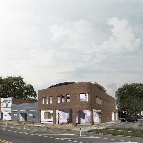
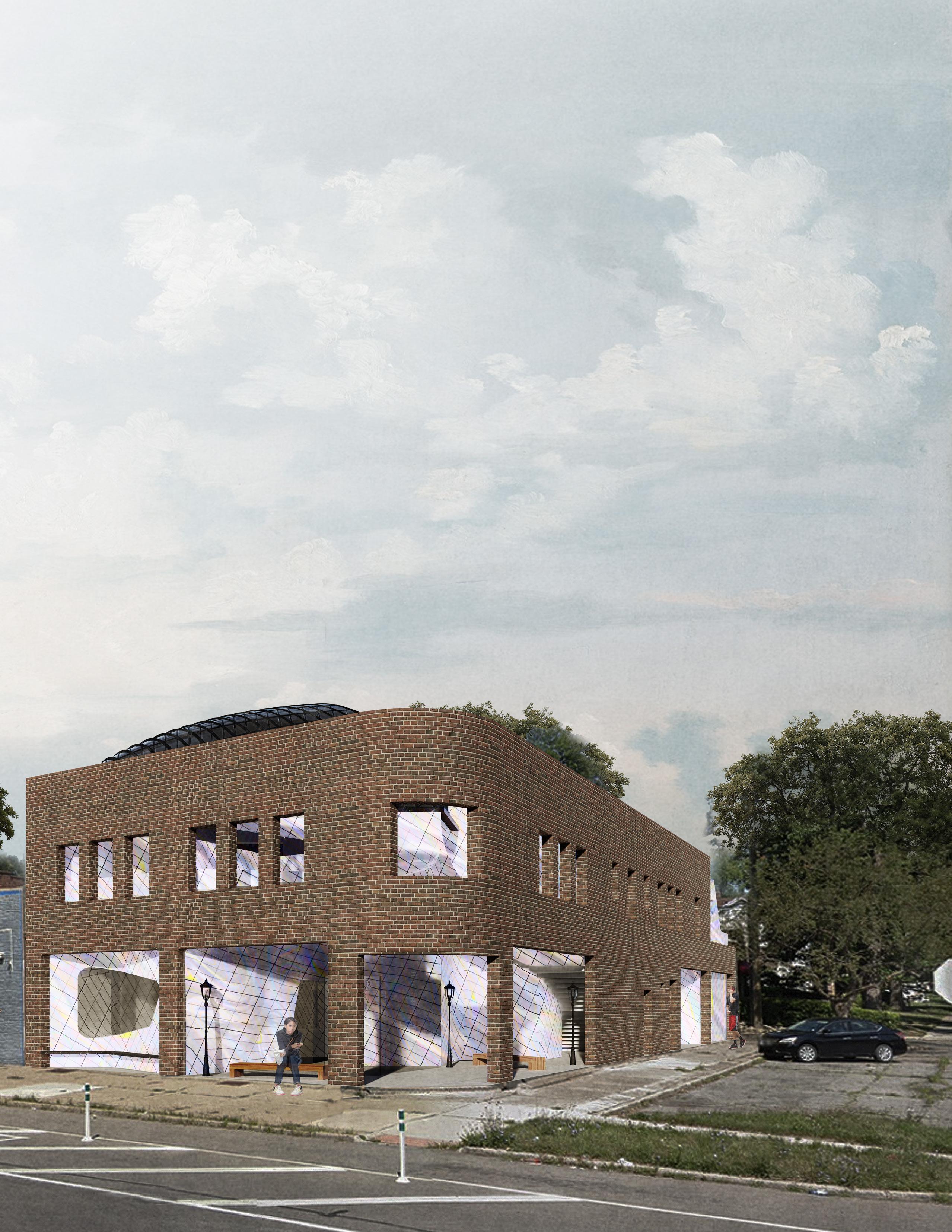
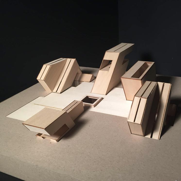
THE HERMIT CRAB
Program: Makerspace, Art Studio, Communal Living
Location: Detroit, MI
Year: Spring 2020
Course: Arch 311 - Situate - Ellen Donnelly
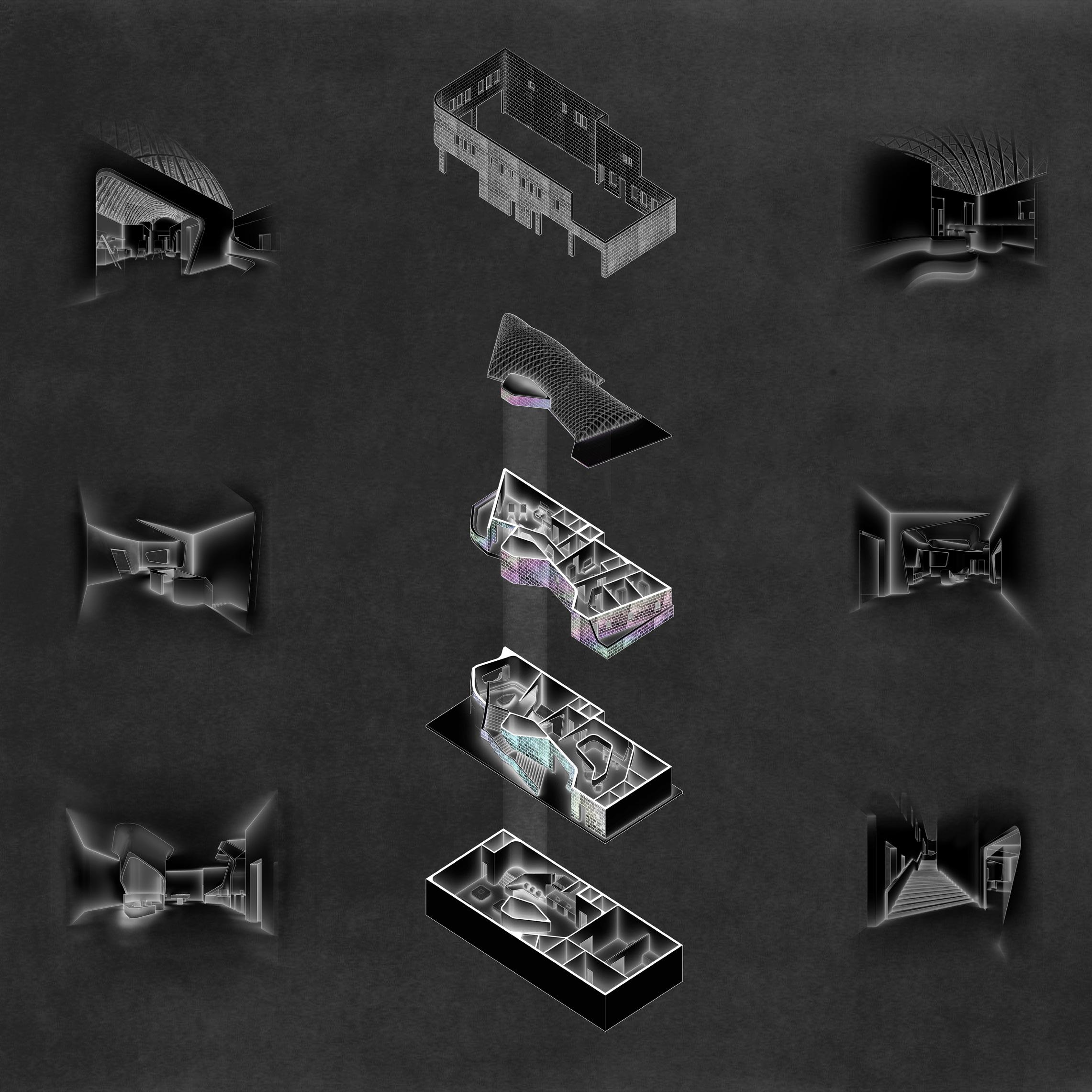
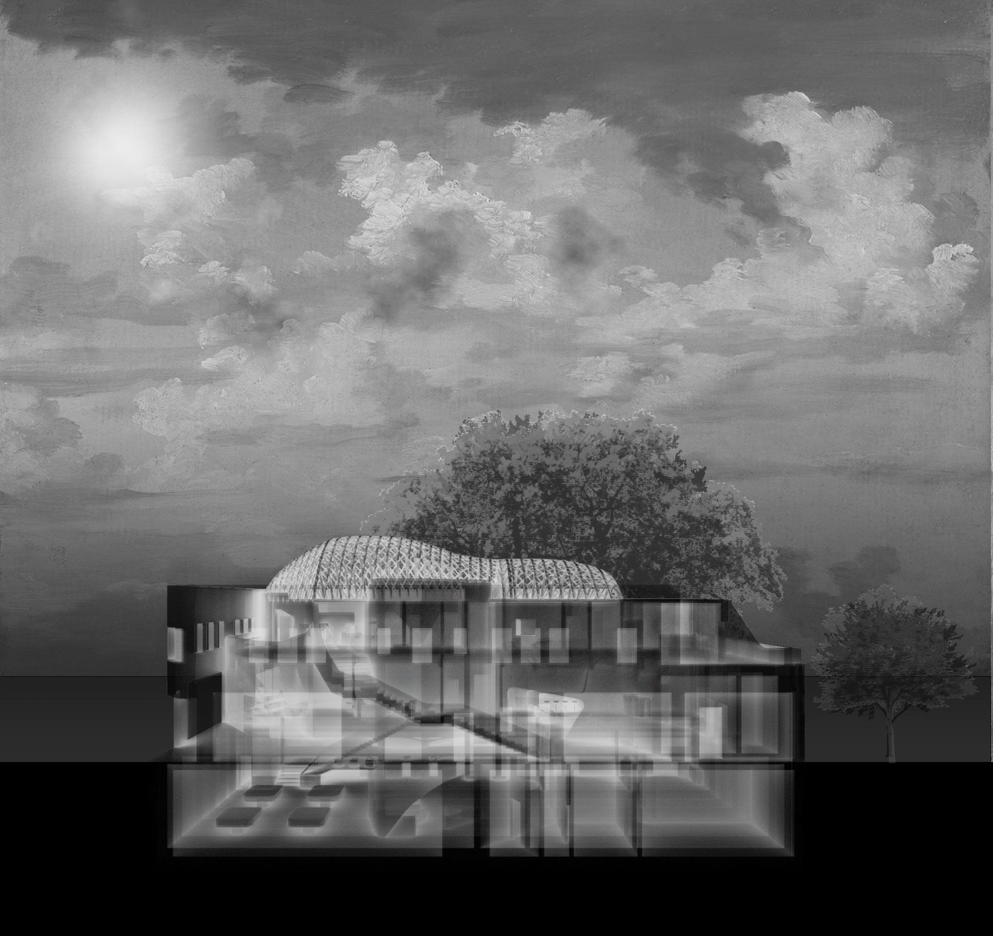
Located within the East Warren neighborhood of Detroit, MI, The Hermit Crab inhabits the shell of a building no longer there. By offering a makerspace, art studio, and communal living, the community of East Warren is presented with opportunities to collaborate, explore, and learn from each other to foster a network of makers, artists, and residents.
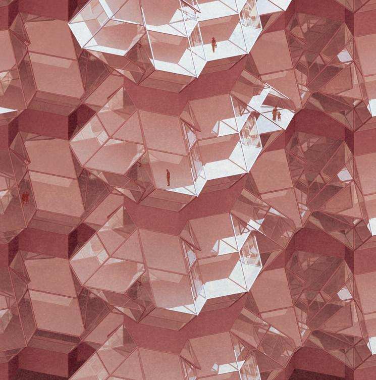
The design is driven by the idea that the building appears to be moving in tandem with the user. This is achieved through the use of malleable surfaces that morph to way suggest changes in motion and activity. The topography of the floors, walls, and ceilings are used to achieve this goal. The design asks occupants to explore the interior and exterior spaces within the shell. The skin of The Hermit Crab is scaled with metallic plates that display an iridescent reflection and aids in contouring the form.
The spaces advocate for social encounters among peers and physical interactions with the building itself.
Exterior Render
(Image produced using a combination of Rhino 3D, Lumion, and Photoshop.)

1
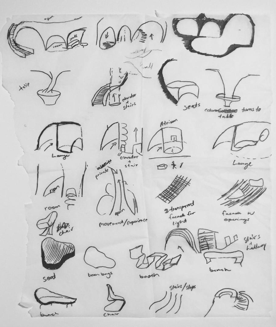
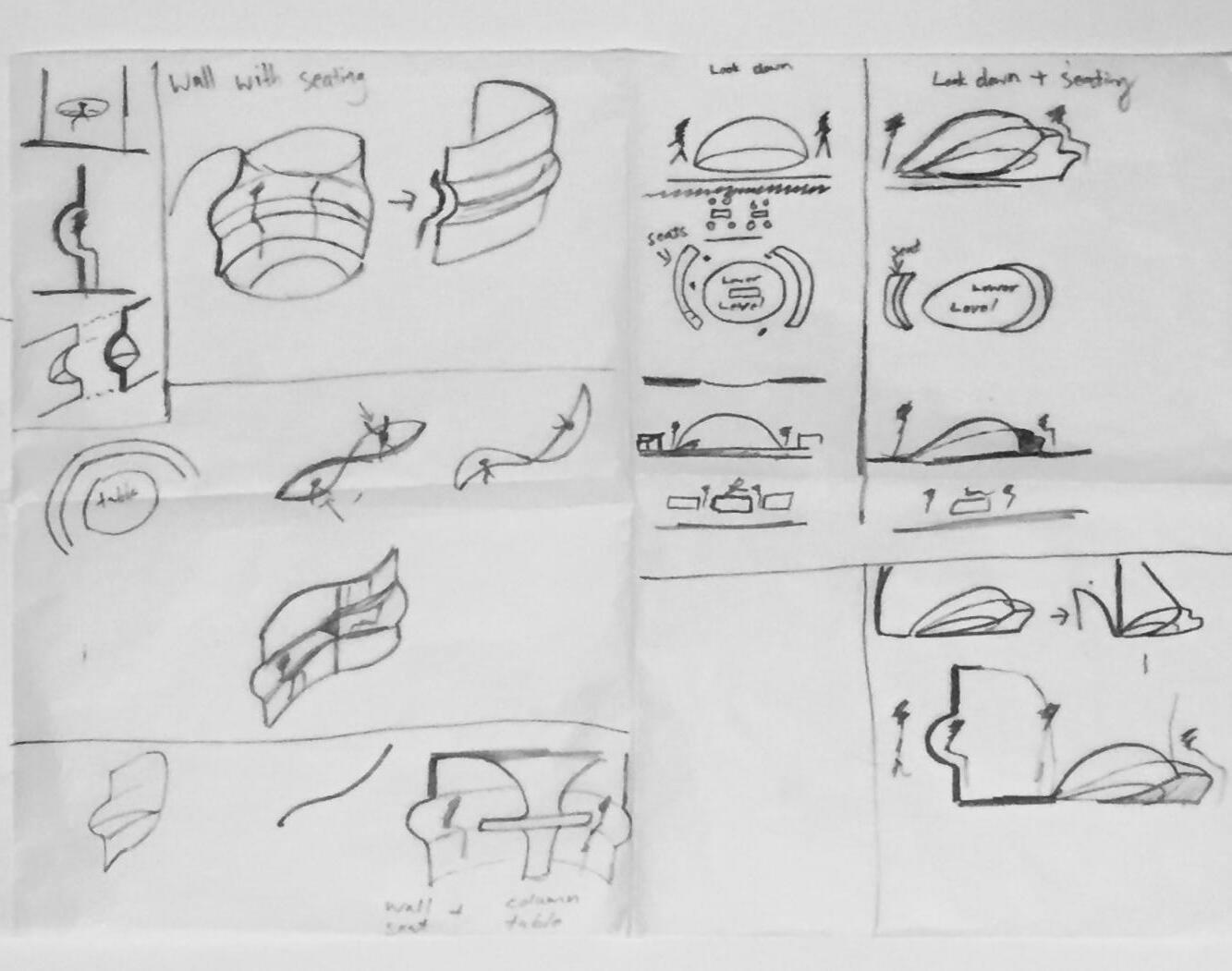


The drawings shown above explore horizontal and vertical qualities to inform the organization of spaces. Such qualities include: intersections, voids, boundaries, circulation, light, and time spent in spaces. There were also various ideas of how surfaces would move and morph. These investigations laid the ground work and were taken as precedents for the design.
3
Horizontal Qualities
Vertical Qualities
4
ART STUDIO
LIVING ROOM
LOUNGE
COFFEE SHOP
MAKERSPACE
EXTERIOR STAIRS
Above: Exploded Axon
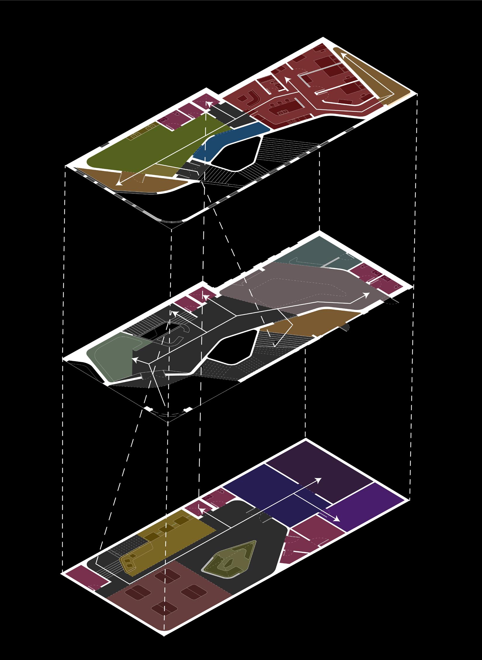
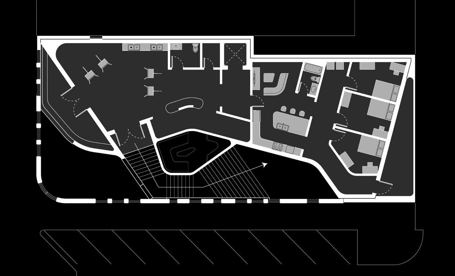
On the ground floor, users are provided with a lounging space as well as a small coffee shop. Occupants are presented with the option to follow the exterior stairs up to the second floor housing the art studio and communal living or follow the stairs down leading to the makerspace.
5
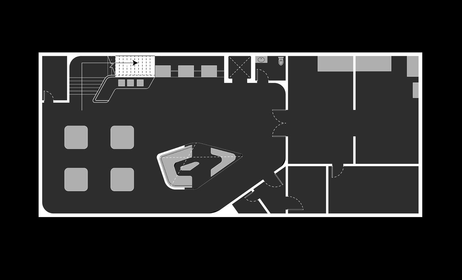
1 - Lounge 2 - Cafe 3 - Bar 4 - Storage 5 - Restroom 6 - Elevator 7 - Art Studio 8 - Gallery 9 - Communal Living Room 10 - Bedroom 11 - Deck 12 - Lounge (Light Well) 13 - Work Benches 14 - 3D Printing 15 - Wood Working Shop 16 - Metal Shop 17 - Cnc Shop 18 - Mechanical Room LEGEND
Above: Circulation + Program Diagram
6
Ground Floor
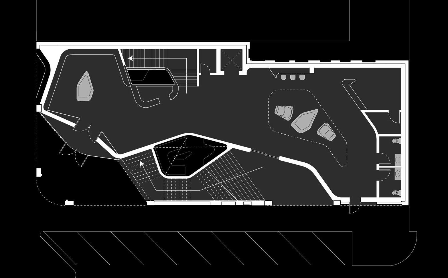
Makerspace Floor
B A AA BB 5 6 10 9 10 11 10 8 7 11 1 4 13 14 12 5 15 16 17 18 6 5 5 3 2 4 4 4 6
Art Studio Floor
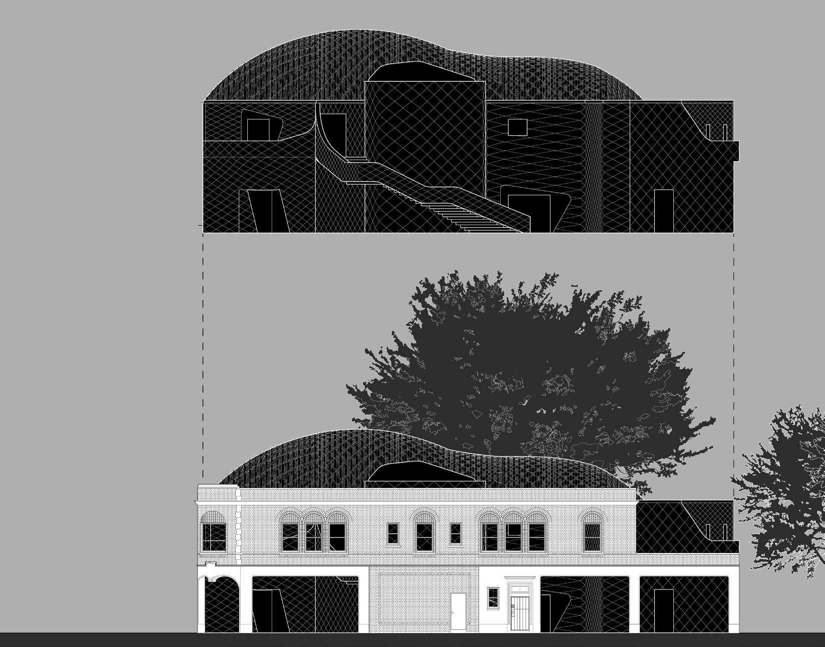

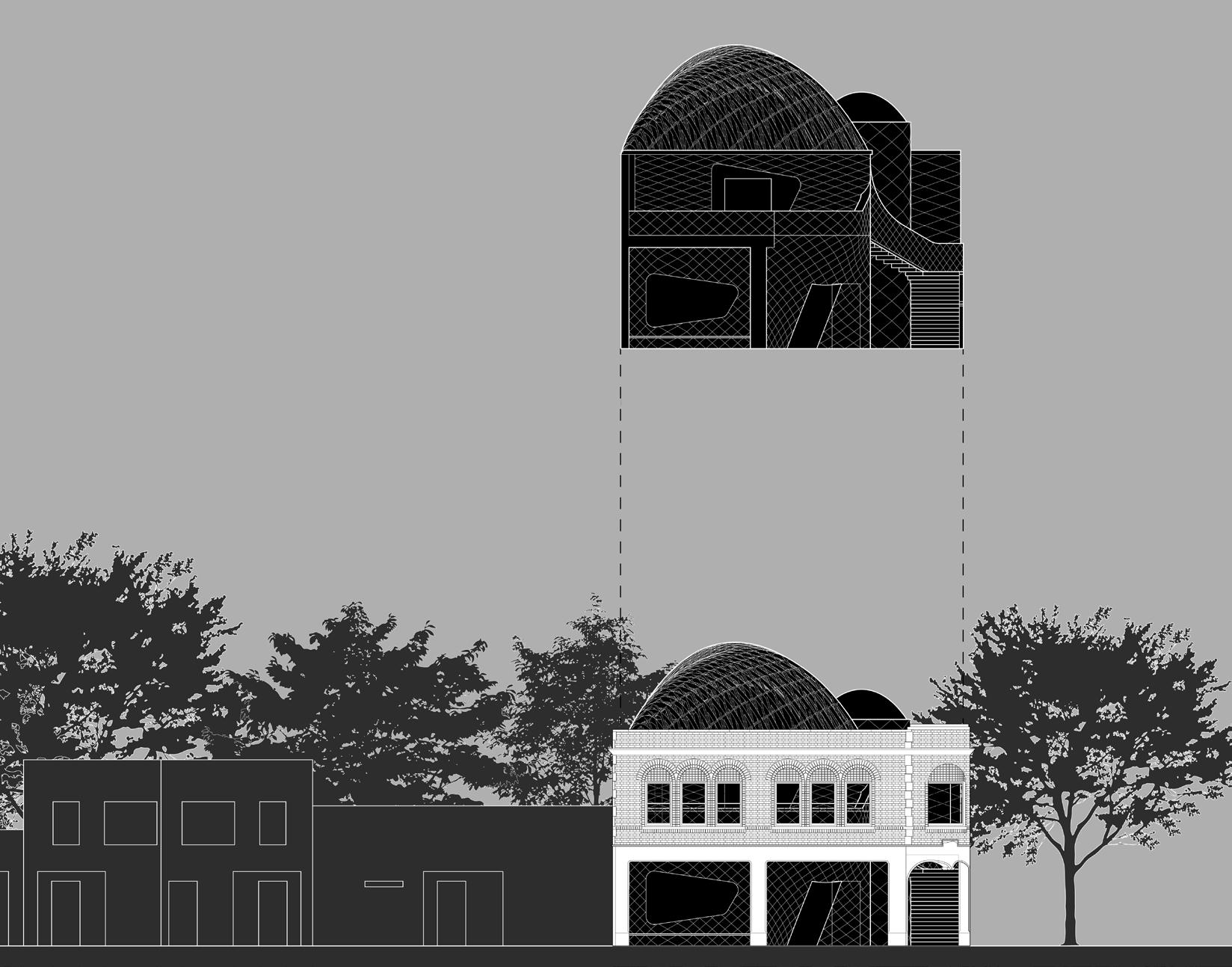
The skin of the facade takes the brick pattern of the shell and shears it to juxtapose it. Ceilings and walls work as one continuous moving surface. Ceilings define spaces and walls direct movement as well as becoming staircases, seating, and counters.
7
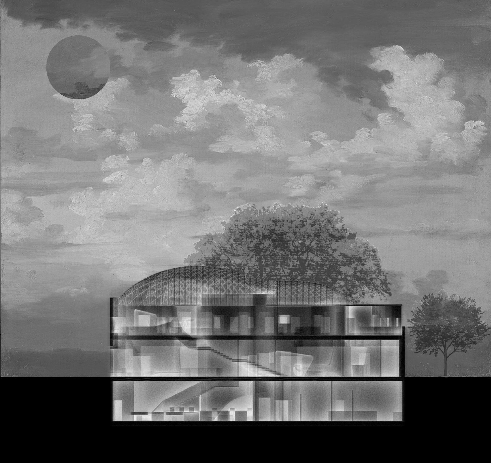
Above: Elevation + Section East Elevation
Section A:AA
On the top floor, the art studio, gallery, and living room are filled with natural light that filters through the curved glass roof and truss frame structure. The lounge in the makerspace is emphasized with the natural light captured up by the glass roof. This allows for a change in scale and an experiential moment.
8
Above: Elevation + Section
South Elevation
Section B:BB
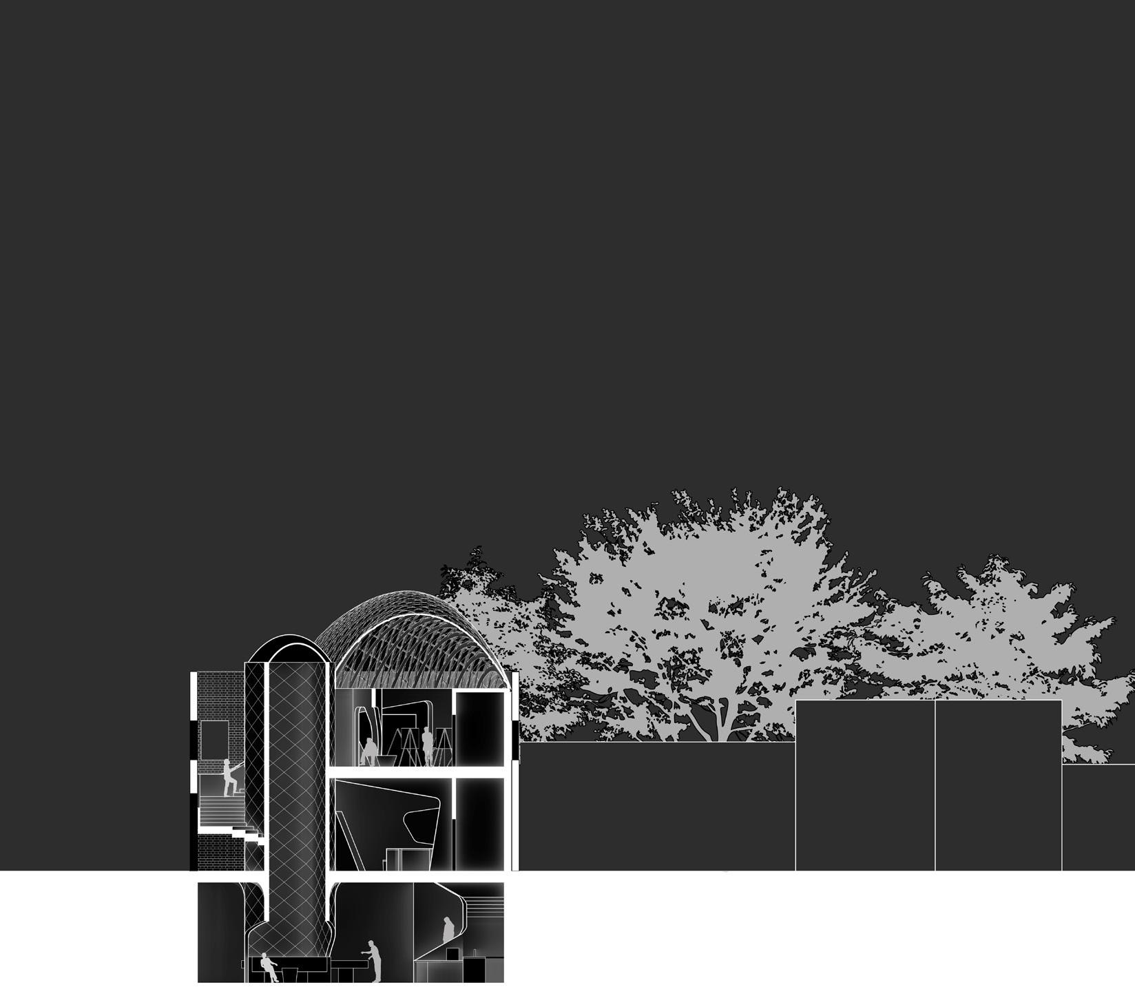
The architecture of this design is predicated on the maliable surfaces prompting users to engage with the building as a living entity both vertically and horizontally as much as with others in a multitude of instances. These X-rays illustrate the motion of The Hermit Crab in its entirety.
9
Above: X-Ray Section Perspective
10
Above: X-Ray Section
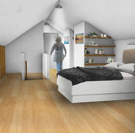
ATTIC CONVERSION
Collaborators:
Tim Murphy - Structural Engineer - Wilson & Company, Inc.,
Jose Ochoa - Contractor - J Builds LLC
Program: Master Bedroom, Bathroom, Closet
Location: Omaha, NE
Year: Summer 2023 (Completed)
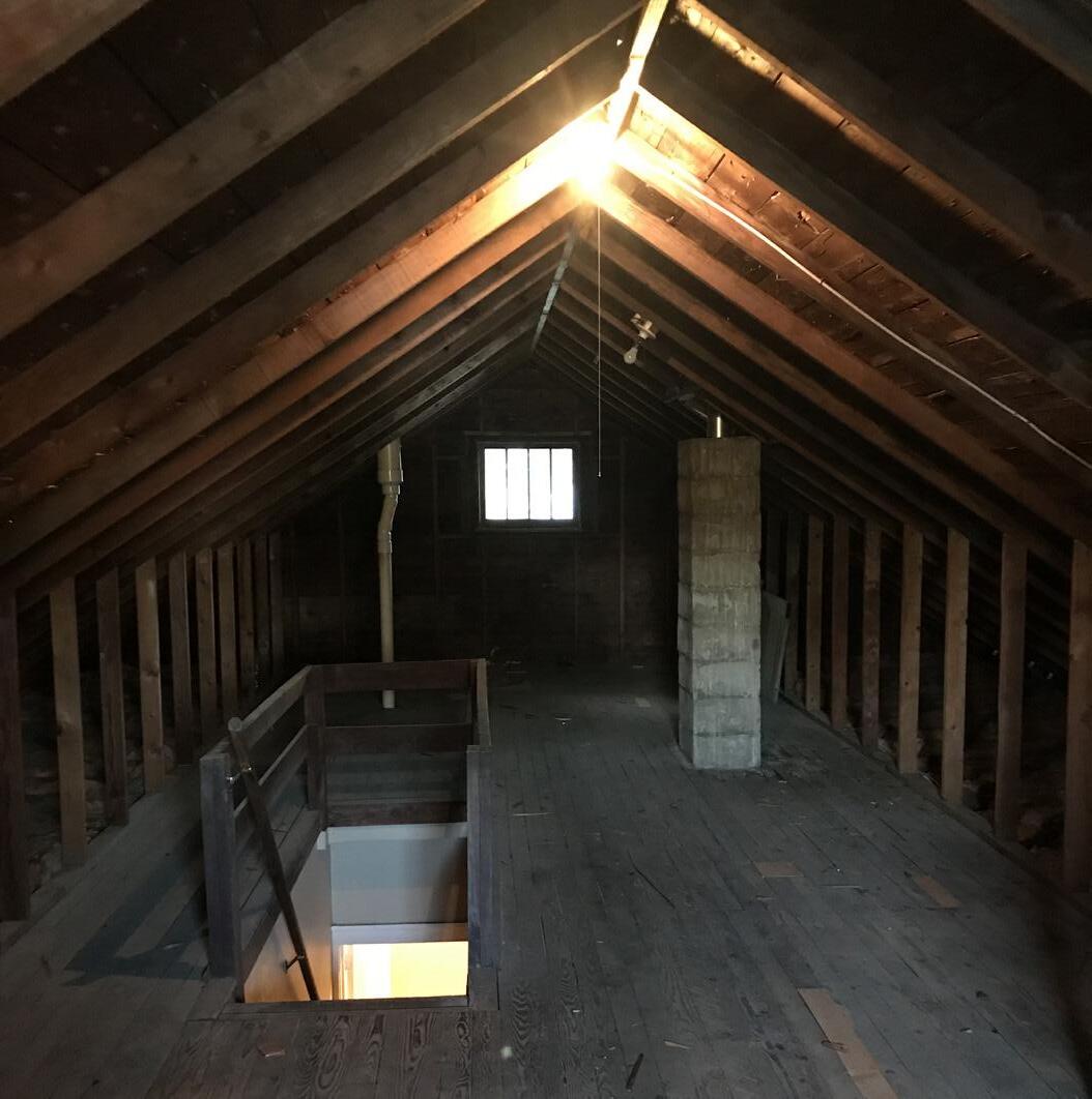
Located in the Historic Benson neighborhood of Omaha, NE, this design focuses on modifying an existing element into a space that provides convenience.
There was an emphasis on effectively utilizing as much space as possible, this goal even extended as far as to taking advantage of the spacing between studs in the existing knee walls. In the end, project resulted in a Master Bedroom with a bathroom, two closets, and built-in drawers offering the client functionality and comfort.
Throughout the duration of the project, I acted as the architectural designer, consultant, and coordinator. Not only did I design the conversion but I also worked alongside the client to indentify what problems needed solving. I provided multiple iterations of possible outcomes. I collaborated with the Structural Engineer in ensuring the structural integrity of the project. Finally, I acted as the main point of contact for the contractor to direct any questions and additional information requests for the project.
This project provided challenging obstacles and a valuable learning experience. It was accomplished through the collaborative efforts of all parties involved.
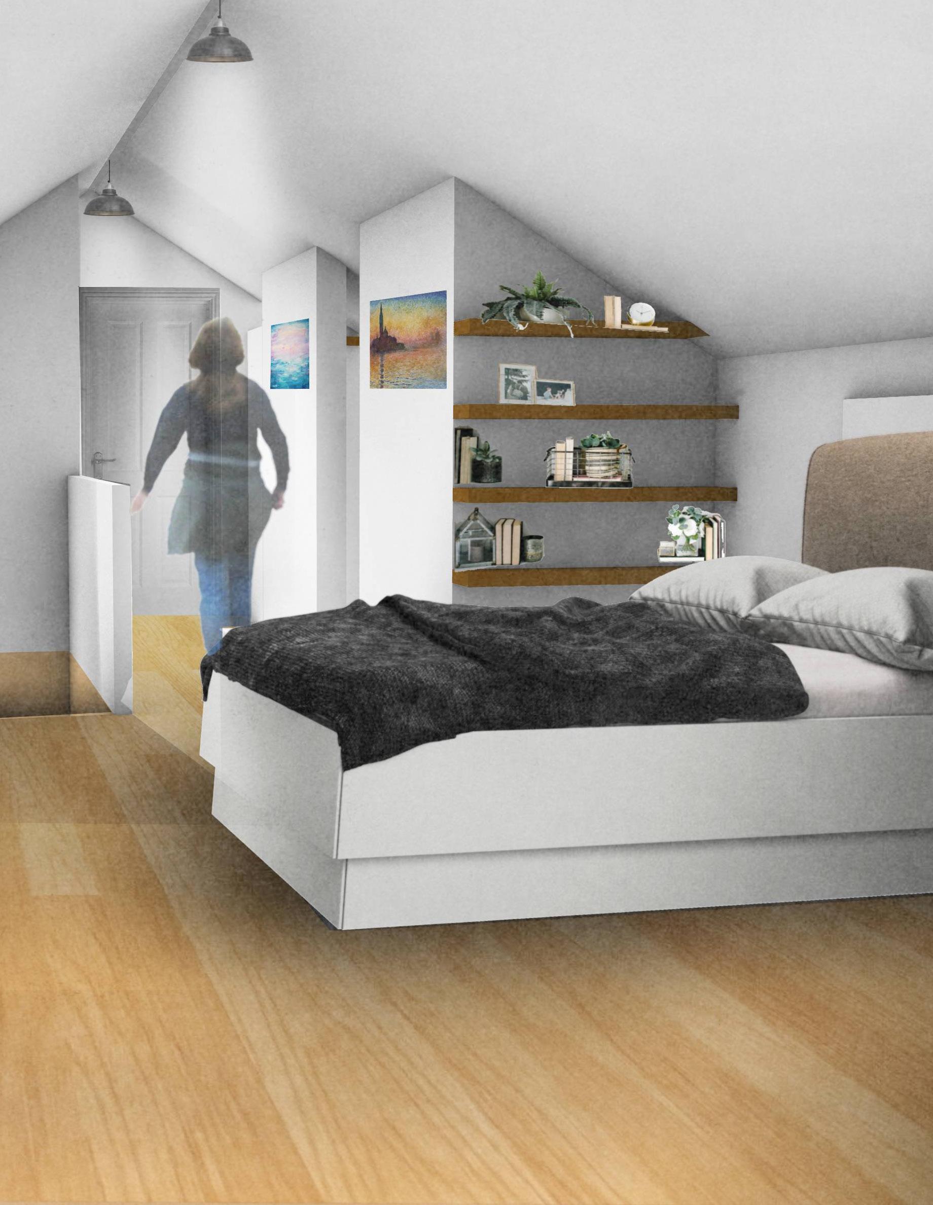
Proposal Bedroom Perspective
(Image produced using a combination of Rhino 3D and Photoshop.)

11
12
Before: Facing West Towards Bathroom
After: Facing West Towards Bathroom
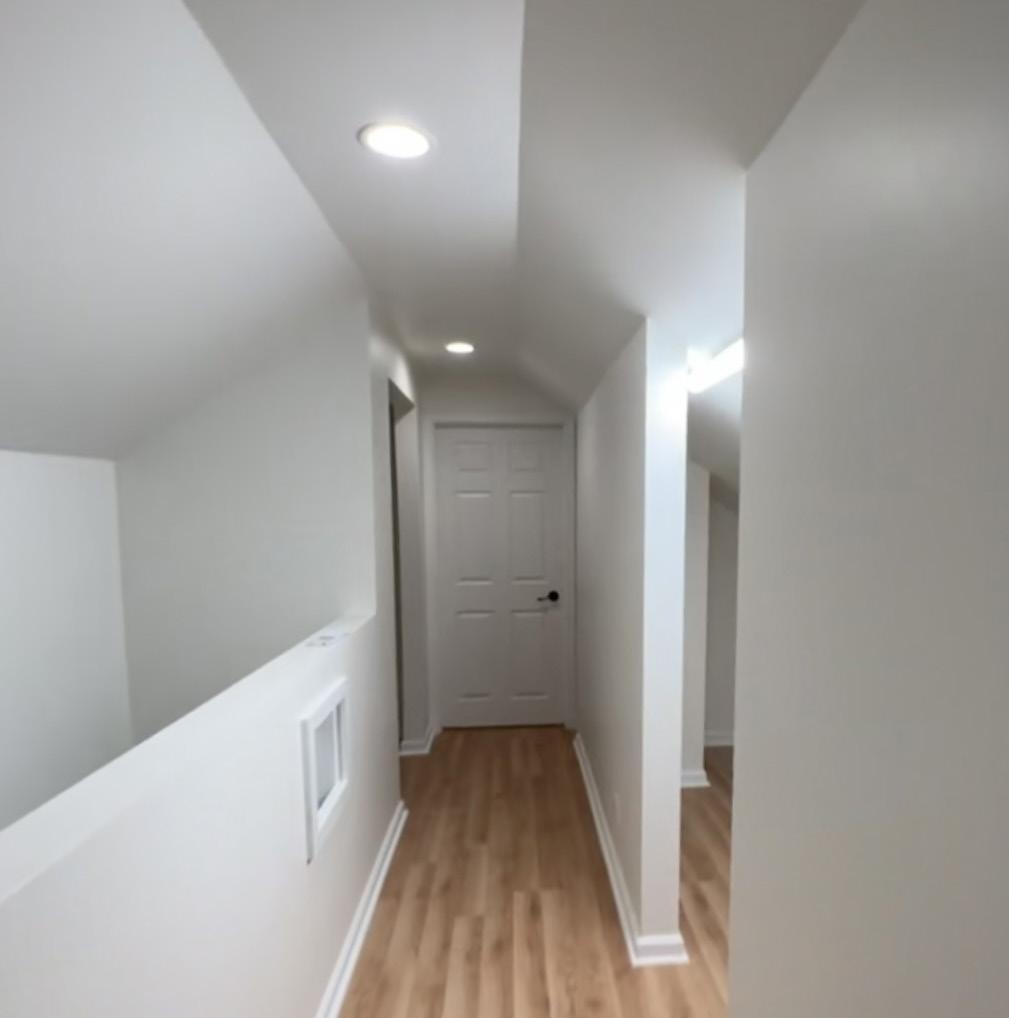
An issue the client wished to address was the lack of space in their room which led them to use a spare room for clothing storage and their vanity. Though a solution to this obstacle could have been to extend the bedroom into their office, it was not ideal for the needs and comfort for the client.
13
Above: Proposal Interior Renders Page 14: Proposal Axon
EXISTING 2” x 4” - 24“ O.C. RAFTERS
EXISTING 2” x 4” - 24“ O.C. KNEE WALL
BEDROOM
DISPLAY SPACE
CLOSET #3
CLOSET #2
14
CLOSET #1 BATHROOM
NEW 2” x 6” - 24” O.C. RAFTERS (SISTERED TO EXISITING 2” x 4” RAFTERS WITH 1 1/2” GAP TO ACHIEVE 7”)
EX. 2” x 4” - 24” O.C. RAFTERS
GUTTERS
FLASHING
EX. 1” x 8” FASCIA
EX. 3/8” SOFFIT
EX. HARDBOARD SIDING
EX. 2” x 10” RIM JOIST
EX. ASPHALT SHINGLES
EX. FELT
12 7
EX. 1/2” OSB SHEATHING
R- 19 INSULATION
EX. 2 - 2” x 4” TOP PLATE
R- 13 INSULATION
EX. 2” x 4” BOTTOM PLATE EX.
EX. 2” x 4” - 16” O.C.
EX. LATH AND PLASTER
EX. 2” x 8” TREATED SILL EX.
5/8” ANCHOR BOLTS @ 40” O.C. EMBEDDED 15” MIN.
#5 REBAR @ 40” O.C.
13 COURSES - 8” CONC. BLOCK
CONCRETE FOOTING
NEW R- 49 INSULATION (7” CLOSED CELL SPRAY FOAM)
NEW 1/2” DRYWALL
EX. 2” x 4” - 24” O.C.
(SEE DETAILS FOR REWORK, WHERE REQUIRED)
EX. 2” x 6” - 16” O.C. CEILING JOISTS
2” x
10” - 16” O.C.
2” x 4” BOTTOM
NEW CONT. 2” x 4” BRACE
PLATE
GRADE
3/4”
& G
(RATED
40 PSF
16”
3/4”
EX. 3/4” SHEATHING DAMP-PROOFING
CONCRETE DRAIN TILE NEW
T
SHEATHING
FOR
WITH JOIST SPACING AT
O.C.) EX.
T & G SHEATHING CONCRETE FLOOR
SECTION 1 DETAIL SCALE: 1/2” = 1’- 0” 15 A103: Wall Section Detail
1. Existing Roof Rafters 2” x 4” @ 24” O.C. will be sistered using 2” x 6” Joists.
2. Existing Knee Wall Studs will remain in place.
3. Existing Windows are both 2’-6” x 2’-6” and will be replaced with new ones of similar dimensions.
4. Existing Plumbing Pipes will not be rerouted and will be framed around.
5. Existing Trap Door will be replaced with a new door.
6. Half Wall will measure a height
4'-10" 9'-4" 5'-3" 5'-3" 2'-2 3 4 " 6'-8 3 4 " 6'-3" 37'-2" 11'-6 1 2 " 14'-0" 6'-2 1 4 " 3'-0" 9'-2 1 4 " 3'-0" 3'-6" 3'-0" 3'-0" 3'-10 1 2 " 5'-0" 3'-4 1 2 " 8'-10 1 2 " 12'-9" 11'-10 5 8 " 4'-0 1 2 " 13'-7" 6'-4 1 2 " 11'-0" 0’ 5’ 10’ 15’ 30’ ATTIC FLOOR PLAN Title Sheet Number A102 DN 2 x 6 Rafters Sistered Half Wall (Height: 3’-6”) 2’-6” x 2’-6” 2’-6” x 2’-6” 32” 1 6 7 3 5 4 2 CO S N A103 A107 A108 1 1-1 2-2 NOTES LEGEND SYMBOLS 1. Existing Roof Rafters 2” x 4” @ 24” O.C. will be sistered using 2” x 6” Joists. 2. Existing Knee Wall Studs will remain in place. 3. Existing Windows are both 2’-6” x 2’-6” and will be replaced with new ones of similar dimensions. 4. Existing Plumbing Pipes will not be rerouted
will be framed around.
Existing Trap Door will be replaced with a new door. 6. Half Wall will measure a height of 3’- 6”. 7. Restroom Door will have width of 32”. 8. Existing Stairs will be grandfathered in. 1 - Bedroom 2 - Bathroom 3 - Closet #1 4 - Closet #2 5 - Closet #3 6 - Display
7 -
6'-8 3 4
6'-3" 37'-2" 14'-0" 9'-2 1 4 "
LEGEND SYMBOLS
and
5.
Space
Hallway
"
NOTES
of 3’- 6”. 7. Restroom Door will have width of 32”. 8. Existing Stairs will be grandfathered in. 1 - Bedroom Room Number 2 - Bathroom Section Sheet Number 3 - Closet #1 Smoke + Carbon Monoxide Detector 4 - Closet #2 5 - Closet #3 6 - Display Space 7 - Hallway PLAN # # CO S A108 2-2 12'-9" 37'-2" 12'-9" 14'-0" 2'-2 3 4 " 3'-1" 5'-6 1 4 " 10'-11" 2'-2" 12'-3 1 4 " 2'-1 1 4 " O.C. will be rerouted. new DF-LARCH, following: SPECIFICATION basis 2 x 4 Roof Rafters 2’-6” x 2’-6” 2’-6” x 2’-6” 2’-0” DN PLUMBING CHIMNEY PLUMBING TRAP DOOR UNDER WINDOW CLOSET 0’ 5’ 10’ 15’ 30’ N A103 1 A107 A108 1-1 2-2 16 Redesigned Floor Plan Scale: 1/8” = 1’-0”
1. Waste lines will connect to Existing Plumbing
2. A Smoke Detector and Carbon Monoxide Detector are requiredminimum one of each. (Can be a detector that combines both to meet requirement.)
3 The outlet near the sink will be a GFCI Outlet. The rest of the outlets can be normal outlets.
4. Due to the use of closed cell spray and slope, wall mounted lights will be installed in each closet instead of ceiling lights.
5. Outlets in closets are not required and owner will decided if they will be installed.
6. The three Outlets in the Display Space are will be at a height of 3’-0”.
1. Owner will decide if ceiling lights will be recessed or normal lights. Room Number Light Duplex Outlet
4'-2 1 4 6'-6" 6'-6"
5'-0" 0’ 5’ 10’ 15’ 30’
SCALE: 1/4” = 1’-0”
7'-8"
NOTES PLAN
SYMBOLS
S
S S S S L L L
L GFCI CO 0’ 5’ 10’ 15’ 30’ 2044 N 48th Avenue, Omaha, NE 68104 PLUMBING PLAN Title Sheet Number A104 NOTES 1. Waste lines will connect to Existing Plumbing Line unless deemed otherwise by contracted Plumber.
Shower wall where water lines will be placed and wall where sink location will be are to be constructed as a wet wall. 3. Best methods Water Lines and waste lines will be deemed by contracted plumber. PLAN SCALE: 1/4” = 1’-0” SYMBOLS Waste Line Hot Water Cold Water Water Connection Line Waste Direction 0’ 5’ 10’ 15’
GFCI Outlet Wall Mounted Light Smoke + Carbon Monoxide Detector Light Switch S # CO S GFCI
S
L
2.
NOTES
Line unless deemed otherwise by contracted Plumber. 2. Shower wall where water lines will be placed and wall where sink location will be are to be constructed as a wet wall. 3. Best methods Water Lines and waste lines will be deemed by contracted plumber. PLAN SCALE: 1/4” = 1’-0” SYMBOLS Waste Line Hot Water Cold Water Water Connection Line Waste Direction 3'-0" 3'-0" 0’ 5’ 10’ 15’ 30’ 2044 N 48th Avenue, Omaha, NE 68104 MECHINICAL PLANS Title Sheet Number A105 3'-0" 3'-0" 0’ 5’ 10’ 15’
1. Exterior Unit will be routed to interior through ceiling of porch. 2. Best location for the wall vent in the bathroom will be determined by the installer. PLAN SYMBOLS Wall Vent Ductwork Exterior Unit 4'-2 1 4 " 6'-6" 7'-8" 0’ 5’ 10’ 15’ PLAN SCALE: 1/4” = 1’-0” SYMBOLS Room Number Light Duplex Outlet GFCI Outlet Wall Mounted Light Smoke + Carbon Monoxide Detector Light Switch S # CO S GFCI S S S L L L CO S Electrical Plan Plumbing Plan HVAC Plan 17
NOTES
Cabinet Elevation
Sliding Track Cabinet Doors
0'-2 1 2 " 1'-0" 1'-0" 4'-1" 1'-9" 1'-9" 3'-10 1 2 " 0'-2 1 2 " 4'-0 1 2 11'-10 5 8 6'-0 1 2 " 3'-4 1 2 5'-0" 3'-10 1 2 3'-0" 3'-0" 3'-6" 3'-0" 3'-5" 9'-4" 6'-8 3 4 " 5'-3" 5'-3" 9'-2 1 4 " 3'-0" 6'-2 1 4 " 14'-0" 11'-6 1 2 " 37'-2" 2'-2 3 4 6'-3" LOCATION 0’ 5’ 0'-3" 3'-10 1 2 " 0'-2 1 2 " 0'-2 1 2 " 1'-0" 1'-0" 1'-0" 4'-1" 1'-9" 1'-9" 3'-7" 1'-11" 1'-11" 0'-3" 3'-10 1 2 0'-2 1 2 " 0'-2 1 2 " 1'-0"1'-0"1'-0" 4'-1" 1'-9" 1'-9" 3'-7" 1'-11" 1'-11" 2044 N 48th Avenue, Omaha, NE 68104 Title Sheet Number C114 NOTES 1. Sliding Track will be placed 2-1/2” from floor. 2. Sliding Track will have two indents with a depth of 1/4” with a space of 1/2”. Unless a prefabricated sliding track is purchased. 3. Cabinet Doors will be instered onto sliding track and will over lap. 4. Cabinet doors will be made using 1/2” plywood. 5. Shelves will be made using 1/2” or 3/4” plywood. SLIDING CABINETS DIMENSIONS SLIDING
BATHROOM SLIDING TRACK CABINET ELEVATION CABINET DOORS PLAN SCALE: 1” = 1’-0’’ ELEVATION SCALE: 1” = 1’-0’’ ELEVATION SCALE: 1” = 1’-0’’ EXISTING STUDS FACE FRAME SHELF 3/4” PLYWOOD 1/4” WIDTH AND DEPTH FOR EACH TRACK 0'-2 1 2 " 1'-0" 1'-0" 1'-9" 1'-9" 3'-10 1 2 " 0'-2 2 4'-0 1 2 11'-10 5 8 6'-0 1 2 3'-0" 3'-0" 3'-6" 3'-0" 3'-5" 9'-4" 6'-8 3 4 5'-3" 5'-3" 9'-2 1 4 3'-0" 6'-2 1 4 14'-0" 11'-6 1 2 " 37'-2" 2'-2 3 4 " 6'-3" LOCATION 0’ 5’ 0'-3" 3'-10 1 2 0'-2 1 2 0'-2 1 2 1'-0" 1'-0" 1'-0" 4'-1" 1'-9" 1'-9" 3'-7" 1'-11" 1'-11" 0'-3" 3'-10 1 2 0'-2 1 0'-2 1 2 " 1'-0"1'-0"1'-0" 4'-1" 1'-9" 1'-9" 3'-7" 1'-11" 1'-11" 2044 N
Title Sheet Number C114 NOTES placed 2-1/2” from floor. two indents with a depth 1/2”. Unless a prefabricated instered onto sliding track made using 1/2” plywood. using 1/2” or 3/4” plywood.
CABINET
CABINET
PLAN SCALE: 1” = 1’-0’’ ELEVATION SCALE: 1” = 1’-0’’ ELEVATION SCALE: 1” = 1’-0’’ EXISTING STUDS FACE FRAME SHELF 3/4” PLYWOOD 1/4” WIDTH AND DEPTH FOR EACH TRACK 3'-7" 0'-2 1 2 " 1'-0" 1'-0" 4'-1" 1'-9" 1'-9" 3'-10 1 2 " 0'-2 1 2 " 4'-0 1 2 " 11'-10 5 8 " 8'-10 2 6'-0 1 2 " 3'-4 1 2 5'-0" 3'-10 1 2 3'-0" 3'-0" 3'-6" 3'-0" 3'-5" 9'-4" 6'-8 3 4 " 5'-3" 5'-3" 9'-2 1 4 " 3'-0" 6'-2 1 4 " 14'-0" 11'-6 1 2 37'-2" 2'-2 3 4 6'-3" LOCATION 0’ 5’ 0'-3" 3'-10 1 2 " 0'-2 1 2 " 0'-2 1 2 " 1'-0" 1'-0" 1'-0" 4'-1" 1'-9" 1'-9" 3'-7" 1'-11" 1'-11" 0'-3" 3'-10 1 2 0'-2 1 2 " 0'-2 1 2 " 1'-0"1'-0"1'-0" 4'-1" 1'-9" 1'-9" 3'-7" 1'-11" 1'-11" 2044 N 48th Avenue, Omaha, NE 68104 Title Sheet Number C114 NOTES 1. Sliding Track will be placed 2-1/2” from floor. 2. Sliding Track will have two indents with a depth of 1/4” with a space of 1/2”. Unless a prefabricated sliding track is purchased. 3. Cabinet Doors will be instered onto sliding track and will over lap. 4. Cabinet doors will be made using 1/2” plywood. 5. Shelves will be made using 1/2” or 3/4” plywood. SLIDING CABINETS DIMENSIONS
BATHROOM
TRACK CABINET ELEVATION CABINET DOORS PLAN SCALE: 1” = 1’-0’’ ELEVATION SCALE: 1” = 1’-0’’ ELEVATION SCALE: 1” = 1’-0’’ EXISTING STUDS FACE FRAME SHELF 3/4” PLYWOOD 1/4” WIDTH AND DEPTH FOR EACH TRACK 4'-10" 3'-5" 9'-4" 5'-3" 5'-3" 2'-2 3 4 6'-8 3 4 " 6'-3" 37'-2" 11'-6 1 2 14'-0" 6'-2 1 4 " 3'-0" 9'-2 1 4 " 3'-0"3'-6" 3'-0" 3'-0" 3'-10 1 2 5'-0" 3'-4 1 2 8'-10 1 2 12'-9" 11'-10 5 8 " 4'-0 1 2 0’ 5’ 1'-0" 1'-0"1'-0" 1'-0" 5'-3" 0'-9 3 4 1'-10 1 4 3'-2 1 8 " 0'-7 1 2 0'-7 1 2 " 0'-7 1 2 " 0'-7 1 2 " 1'-0 5 8 1'-0" 1'-0" 1'-0" 3'-2 1 8 " 1'-0" 1'-0" 1'-0" 1'-0" 5'-3" 0'-9 3 4 1'-10 1 4 3'-2 1 8 " 0'-7 1 2 0'-7 1 2 " 0'-7 1 2 "0'-7 1 2 " 1'-0 5 8 1'-0" 1'-0" 1'-0" 3'-2 1 8 " 2044 N 48th Avenue, Omaha, NE 68104 Sheet Number CLOSET 2DRAWERS & SHELVES Title C105 NOTES DRAWERS & SHELVES CLOSET 2 DRAWERS + SHELVES SHELVES ELEVATION SCALE: 1” = 1’-0” ELEVATION SCALE: 1” = 1’-0” SLOPED CEILING WALL WALL SHELVES SHELF EXISTING STUDS DRAWER DRAWER DRAWER DRAWER WALL 1. In general, all built-in drawers will follow the same rules of thumb which are the following: - 3/4” plywood will be fastened to stud framing and will serve as box frame for drawers. - Each drawer will be built using 1/2” plywood and will have a max height of 7-1/2” (width will vary upon location.) - Each drawer will be 1” smaller than the space between 3/4” frame plywood (1/2” on each side) to allow room for slide rails. -Drawers will have 1-1/2” vertical spacing between each other. - Drawer covers will have a max height of 9” and will be made using 1/2” plywood.
Face frame is optional and will be decided upon the owner’s decision. Using 1/2” plywood, the width of each piece will be 1”. LOCATION (DRAWERS + SHELVES) LOCATION (SHELVES)
CABINETS
48th Avenue, Omaha, NE 68104
SLIDING CABINETS DIMENSIONS CABINETS SLIDING TRACK
ELEVATION
DOORS
SLIDING CABINETS
SLIDING
-
Drawers + Shelves Shelves
4'-10" 3'-5" 9'-4" 5'-3" 5'-3" 2'-2 3 4 6'-8 3 4 6'-3" 37'-2" 11'-6 1 2 " 14'-0" 6'-2 1 4 " 3'-0" 9'-2 1 4 3'-0"3'-6" 3'-0" 3'-0" 3'-10 1 2 5'-0" 3'-4 1 2 8'-10 1 2 12'-9" 11'-10 5 8 4'-0 1 2 0’ 5’ 1'-0" 1'-0"1'-0" 1'-0" 5'-3" 0'-9 3 4 1'-10 1 4 3'-2 1 8 " 0'-7 1 2 0'-7 1 2 0'-7 1 2 0'-7 1 2 1'-0 5 8 " 1'-0" 1'-0" 1'-0" 3'-2 1 8 1'-0" 1'-0" 1'-0" 1'-0" 5'-3" 0'-9 3 4 1'-10 1 4 3'-2 1 8 " 0'-7 1 2 0'-7 1 2 0'-7 1 2 "0'-7 1 2 1'-0 5 8 " 1'-0" 1'-0" 1'-0" 3'-2 1 8 2044 N 48th Avenue, Omaha, NE 68104 Sheet Number CLOSET 2DRAWERS & SHELVES Title C105 NOTES DRAWERS & SHELVES CLOSET 2 DRAWERS + SHELVES SHELVES ELEVATION SCALE: 1” = 1’-0” ELEVATION SCALE: 1” = 1’-0” SLOPED CEILING WALL WALL SHELVES SHELF EXISTING STUDS DRAWER DRAWER DRAWER DRAWER WALL 1. In general, all built-in drawers will follow the same rules of thumb which are the following: - 3/4” plywood will be fastened to stud framing and will serve as box frame for drawers. - Each drawer will be built using 1/2” plywood and will have a max height of 7-1/2” (width will vary upon location.) - Each drawer will be 1” smaller than the space between 3/4” frame plywood (1/2” on each side) to allow room for slide rails. -Drawers will have 1-1/2” vertical spacing between each other. - Drawer covers will have a max height of 9” and will be made using 1/2” plywood. - Face frame is optional and will be decided upon the owner’s decision. Using 1/2” plywood, the width of each piece will be 1”. LOCATION (DRAWERS + SHELVES) LOCATION (SHELVES) 18
SISTERED 2” x 6” FLOOR JOISTS @ 16” O.C.
EXISTING 2” x 4”
ROOF RAFTERS @ 24” O.C.
SISTERED FLOOR 16” O.C. TWIST STRAP
EXISTING 2” x 4” KNEE WALL STUDS @ 24” O.C.
BOX BEAM
EXTERIOR LOAD BEARING WALL
INTERIOR LOAD BEARING WALL
EXISTING 3 - 2” x 10” BEAM FOUNDATION
WALL ADD COLUMN OR SISTER ADJACENT FLOOR JOISTS, SEE NOTE 1 SHEET A105
Structural Axon
BOX BEAM STRUCTURAL DIAGRAMS
SCALE: N/A
The existing joists in the attic were 2x8’s @ 24” O.C. while the rafters were 2x4 ‘s @ 24” O.C. In order to make the bedroom structurally sound, all joists and rafters were sistered. However, it would not be enough, at which point the Structural Engineer joined to redesign a knee wall into a box beam.
(DET. 1-1 & DET. 2-2 engineered by Tim Murphy - Structural Engineer) Details illustrated by me.
NEW 4” x 4” COLUMNS:
SEE KEYED NOTES. SHEET A 105
NEW COLUMN
SEE KEYED NOTES
DET. 3-3 ON SHEET A 111
FOUNDATION
NEW HEADER WINDOW NEW JACK Jack Studs at each end. Weight will be distributed down to the FOUNDATION WALL. 19
1/2” PLYWOOD APA RATED STRUCTURAL SHEATHING, BOTH SIDES
2” x 4” ROOF RAFTERS WITH 2” x 6” SISTERED ADDED @ 24” O.C.
2'-0" 2'-0" 1'-4" 13'-6" 14'-2" 0’ 5’ 10’ 15’ SISTERED 2” x 6” FLOOR JOISTS @ 16” O.C. EXTERIOR WALL INTERIOR WALL NEW 2 - 2” x 8” NEW 2 - 2” x 8” SPAN TWO ADJACENT NEW 4” x 4” STUB COLUMN NEW 4” x 4” STUB COLUMN NEW 4” x 4” STUB COLUMN NEW 2 - 2” x 4” TOP PLATE EXISTING 2” x 4” TOP PLATE SEE ENLARGED DET. 3-3, A111 SEE ENLARGED DET. 1-1, A109 NEW 2 - 2” x 12” HEADER EXISTING WINDOW 2” x 4” BOTTOM PLATE 2 - 2” x 4” CRIPPLE STUDS @ 16” O.C. GALVANIZED STEEL TWIST STRAP 2” X 4” NEW TOP PLATE EXISTING 2” x 4” KNEE WALL STUDS @ 24” O.C. EXISTING
using will O.C. the 4” will into down to sistered LOAD BEARING additional DET. 1-1 DETAIL SCALE: 1/2” = 1’- 0” 10'-3 5 8 " 6'-4 7 8 " 3'-6" 6'-4" 5'-10" 1'-0" 2'-0" SEE ENLARGED DET.
A110 SISTERED 2”
6”
JOISTS
16”
MIN. BRG. INTERIOR LOAD BEARING WALL EXTERIOR LOAD BEARING WALL NEW 2 - 2” x 4” JACK STUDS NEW 2 - 2” x 12” HEADER OVER WINDOW NEW 2 - 2” x 4” CRIPPLE STUDS 1/2” PLYWOOD APA RATED STRUCUTRAL SHEATING, BOTH SIDES TWIST STRAP EXISTING 2” x 4” KNEE WALL STUDS @ 24” O.C. 2” x 4” TOP PLATE 2” x 4” CONT. BRACE BOTH SIDES 2 - 2” x 8” SPAN CRIPPLE STUDS BELOW 2” x 4” BOTTOM PLATE EXISTING 2” x 4” ROOF RAFTERS @ 24” O.C. WITH SISTERED 2’ x 6” O.C. using will O.C. the every x 4” will window into down to sistered LOAD BEARING additional
2-2
SCALE: 1/2” = 1’- 0” 20
DET. 2-2 - Box Beam
DET. 1-1 - Box Beam
2-2,
x
FLOOR
@
O.C. 1-1/2”
DET.
DETAIL
A108:
A107:
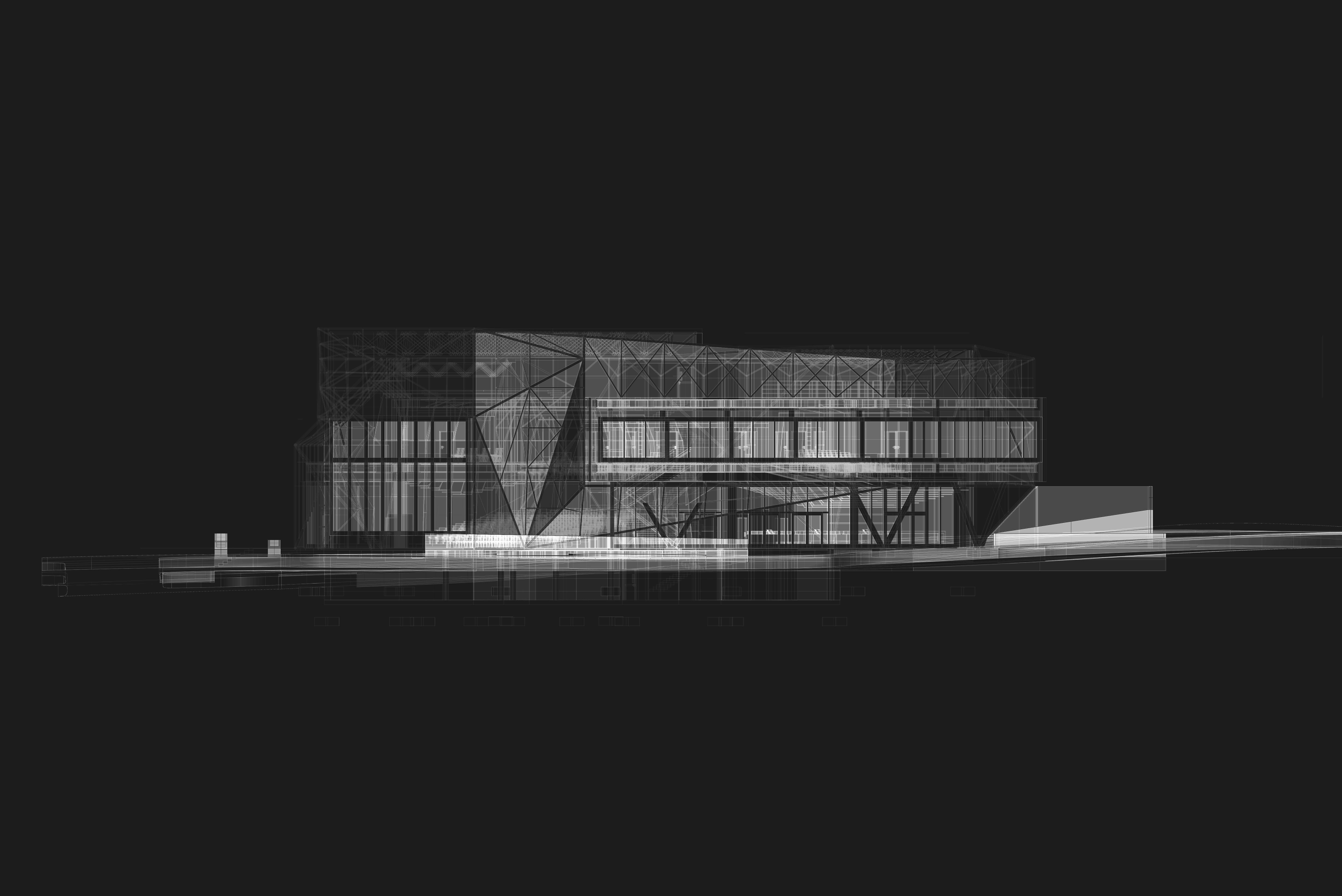
BENSON MUSIC CENTER
Team: Jesus Perez-Cortez, Byron Ho
Program: Music Hall, Classroom, Market Space
Location: Omaha, NE
Year: Spring 2021
Course: Arch 411 - Integrage - Mark Heir, Ashley Byars
Benson Music Center is dedicated to the experience of music within the Benson Community. By taking the logistics of the affects concave and convex surfaces have on sound, this idea is expressed through materials and surfaces as much as exterior and interior relationships.
Within the Benson Music Center, music is experienced through performance, education, rehearsal, history, objects, and how surfaces affect sound. The main performance hall has windows allowing passerbys to witness ongoing activities and can open up to the public to become an outdoor performance space. By providing a market space and lesson rooms, local vendors and music teachers are encouraged to share their goods and services with the Benson population. The rotating exhibition space displays the music history present within Benson and the larger Omaha area.
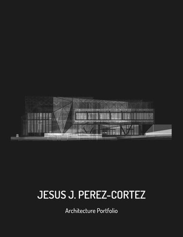
DIFFRACTION
JESUS PEREZ-CORTEZ
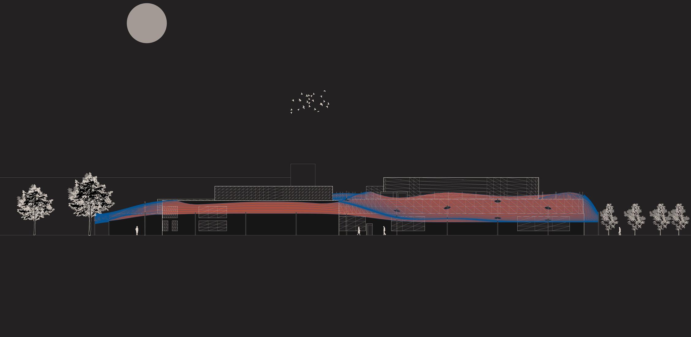
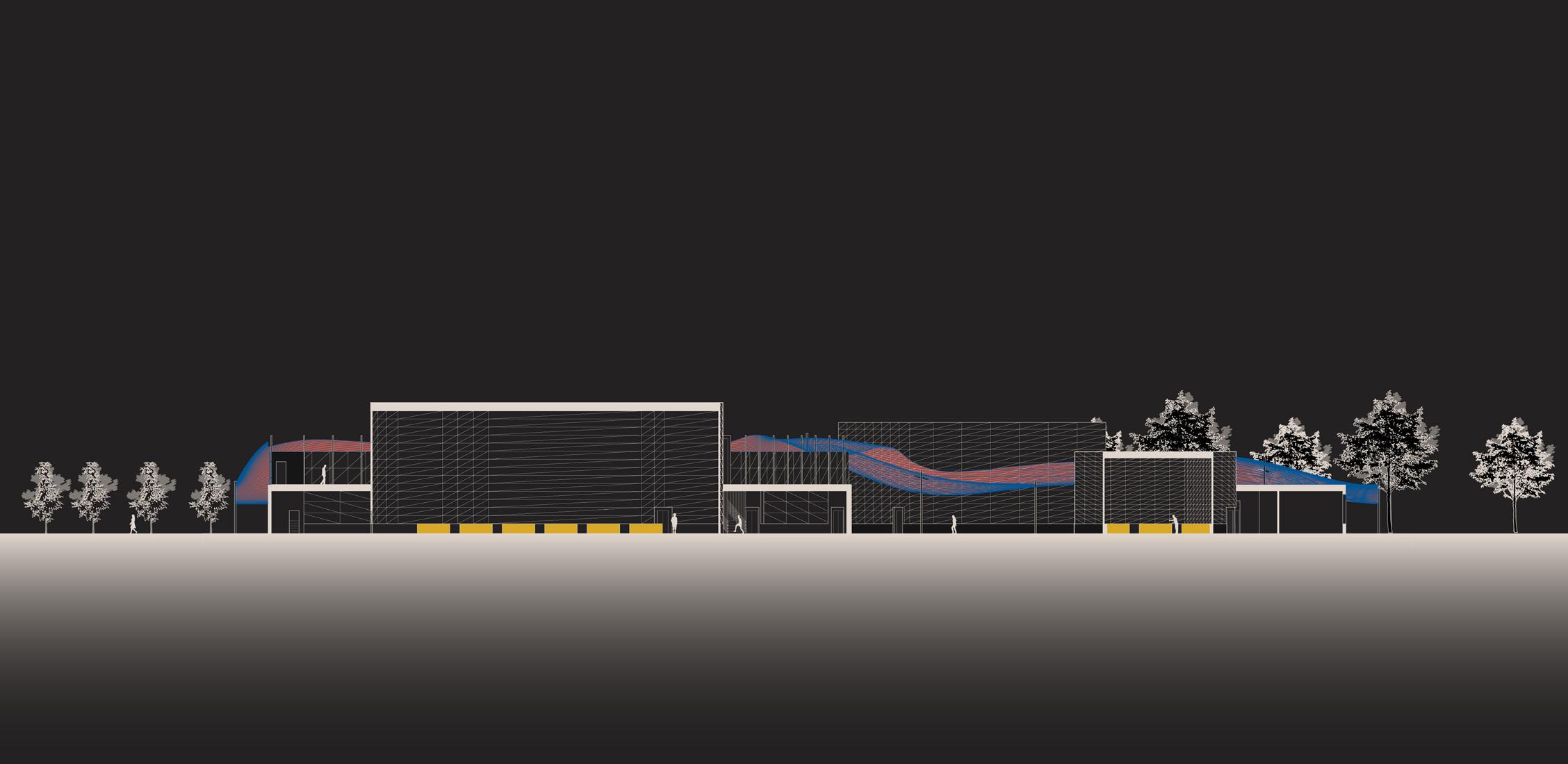
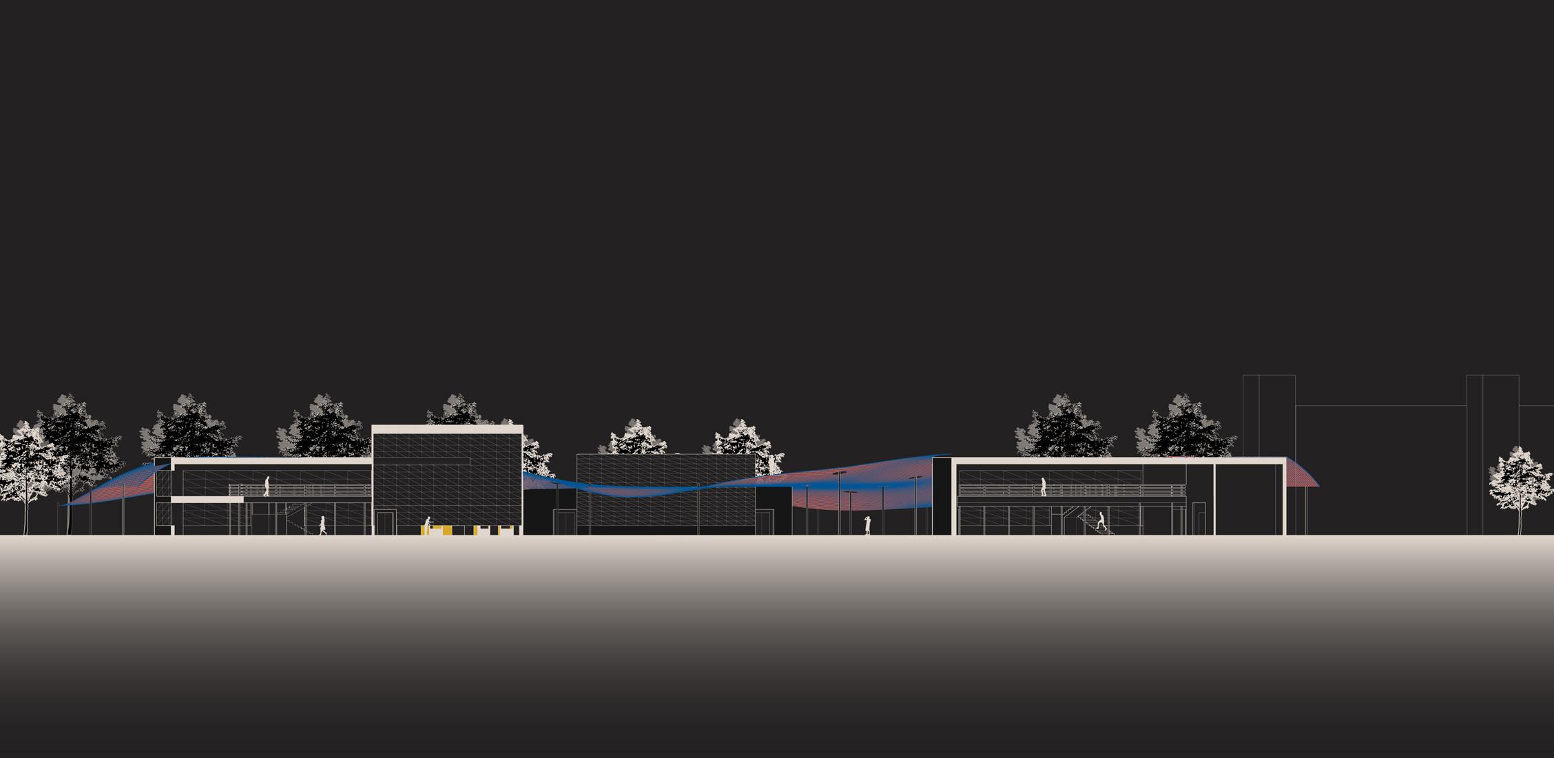
The architecture is veiled in a mesh facade extending the notion of convexity and concavity, providing enclosed and open spaces.
DIFFRACTION
BYRON HO
JESUS PEREZ-CORTEZ
BYRON HO
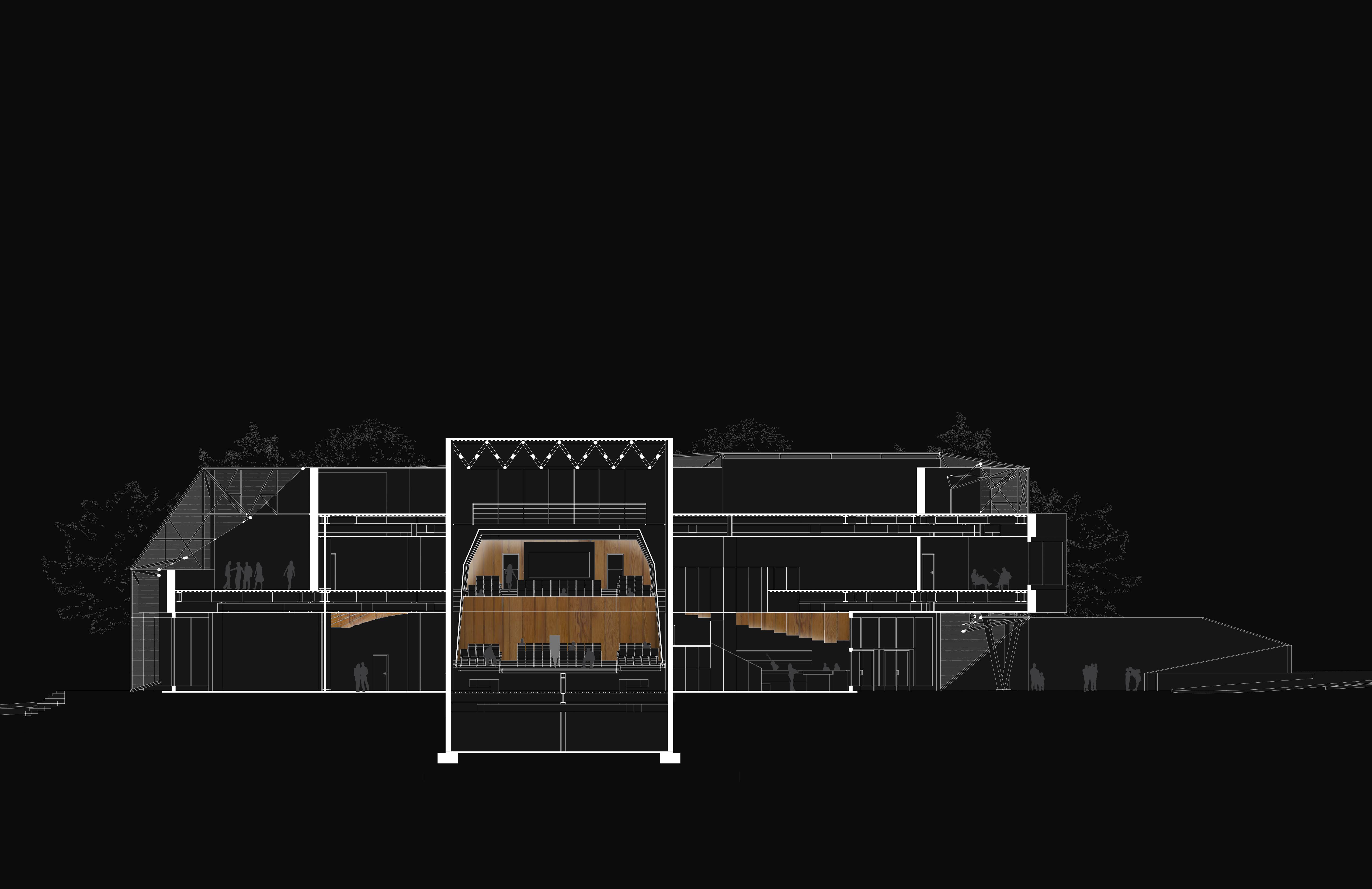
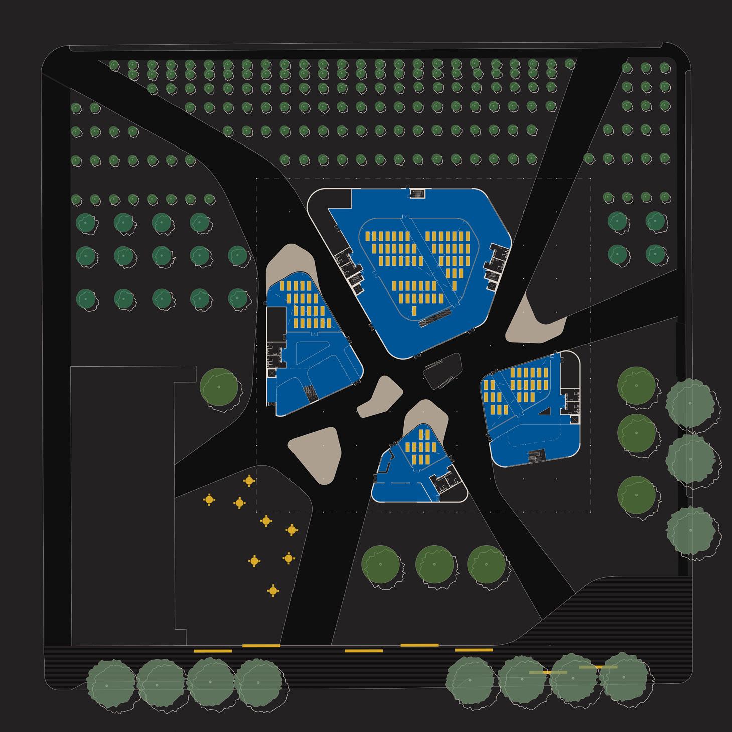
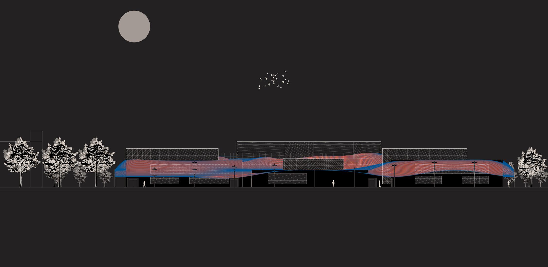
X-Ray of South Elevation
(Image produced using a combination of Rhino 3D, Photoshop, and Illustrator.)
21
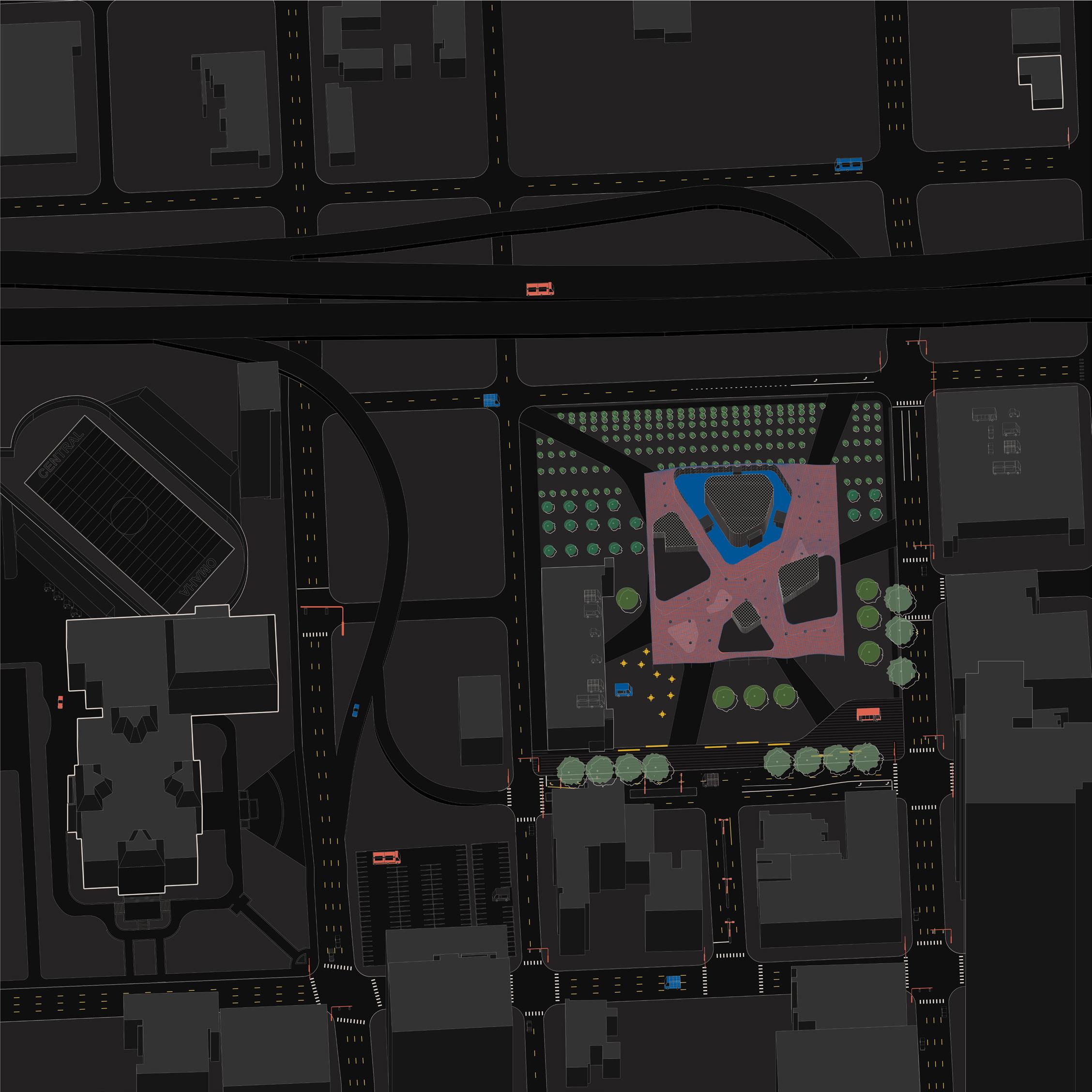
NWRADIALHWY
A key notion during the concept phase was how each street along the site could essentially act as a spectator for music in an audible and educational manner. Above: Site Plan
23
MAPLE STREET
59TH STREET
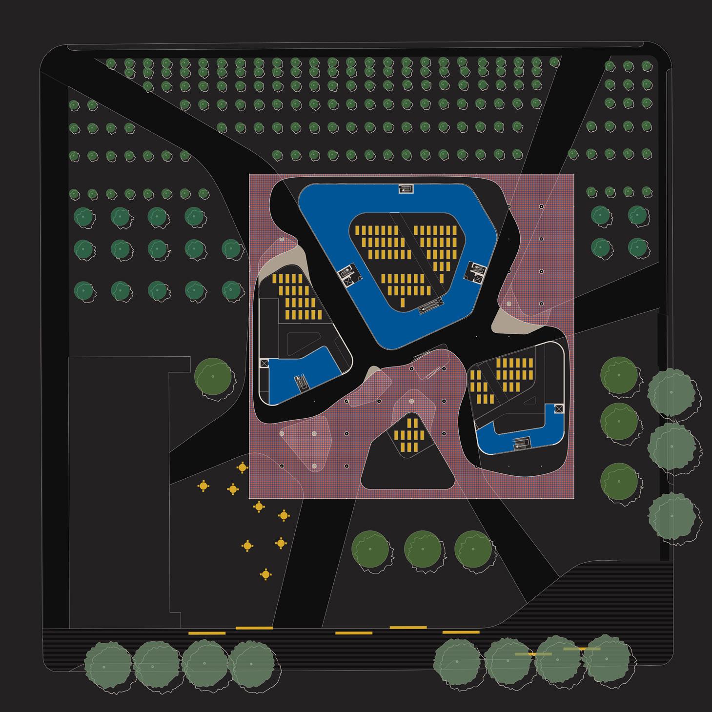
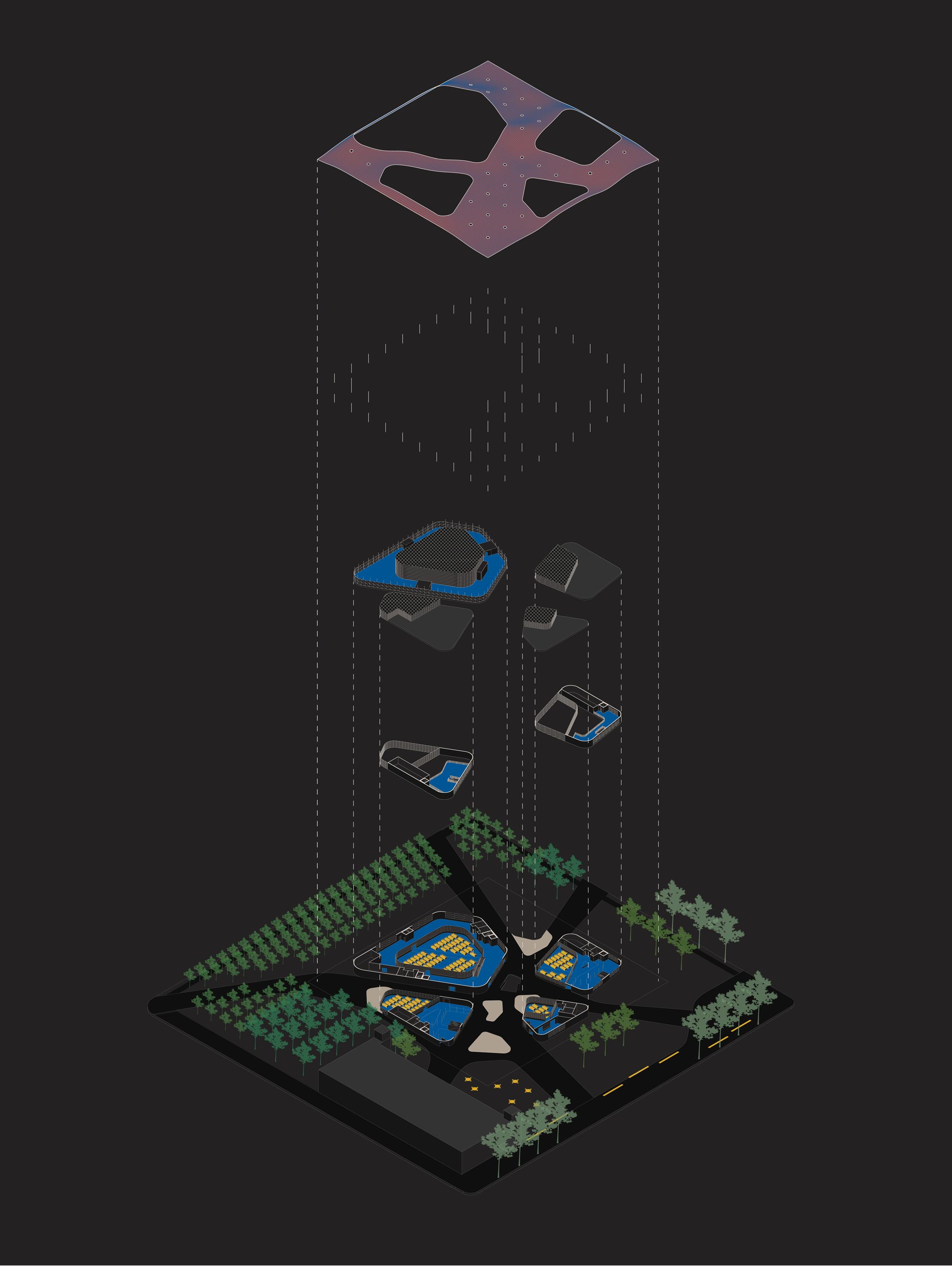
1. Three performance spaces are established. Each is oriented to its own side and has a different scale.
2. The three performance spaces are encased within one volume but remain seperate.
4. Conteracting the obscurity, the facade is lifted and punctured to provide visibility into the building while highlighting the activity occuring inside.
3. A seemingly weightless facade acts as a veil for the imposing structure. It encloses sound and program within its boundaries. The interior activity becomes obscured to the pubilic.
5. The exterior becomes an extension of the interior program, provide spaces for an outdoor performance and an out door market.
Section A Parking Section A Walking Section A Businesses Section A Daylight January Febuary June July August September October November December Average 12.2hr 9.5hr 15 hr hr14 hr12.5 11 hr 10 hr 9.5hr BENSON, NEBRASKA 5 Min Walk 10-12 Min Walk 15-20 Min Walk 60’-0” maximum build height site 310’-0” historic downtown maple street Section A Parking Section A Walking Section A Businesses Section A Daylight January Febuary March April May June July August September October November December Average 12.2hr 9.5hr 10.5hr 12 hr14.5 hr15 15 hr hr14 hr12.5 11 hr 10 hr 9.5hr BENSON, NEBRASKA 5 Min Walk 10-12 Min Walk 15-20 Min Walk 60’-0” maximum build height site 310’-0” historic downtown maple street 60’-0” maximum build height site 310’-0” historic downtown maple street January Febuary March April May June July August September October November December Average 12.2 hr 9.5hr 10.5hr 12 hr 13.5 hr hr14.5 hr15 15 hr hr14 hr12.5 11 hr 10 hr 9.5hr BENSON, NEBRASKA 60’-0” maximum build height historic downtown commercial site 270’-0” SITE ANALYSIS Section A Parking Section A Walking Section A Section A Daylight January Febuary March April May June July August September October November December Average 12.2hr 9.5hr 10.5hr 12 hr 13.5 hr hr14.5 hr15 hr14 hr12.5 hr 10 hr 9.5hr Min Walk 60’-0” maximum build height site 310’-0” historic downtown Section A Parking Section A Walking Section A Section A Daylight January Febuary March April May June July August September October November December Average 12.2hr 9.5hr 10.5hr 12 hr 13.5 hr hr14.5 hr15 hr14 hr12.5 hr 10 hr 9.5hr Min Walk 60’-0” maximum build height site 310’-0” historic downtown 60’-0” maximum build height site 310’-0” historic downtown maple street January Febuary March April May June July August September October November December Average 12.2hr 9.5hr 10.5hr 12 hr 13.5 hr hr14.5 hr15 hr14 hr12.5 11 hr 10 hr 9.5hr BENSON, NEBRASKA 60’-0” maximum build height historic downtown commercial site 270’-0” Byron Ho Jesus Perez-Cortez Arch 411 Spring 2020 Hier & Byars SITE ANALYSIS Byron Ho Jesus Perez-Cortez Arch 411 Spring 2020 Hier & Byars G 104
MASSING DIAGRAM MAPLESTREET 59THSTREET NW RADIAL HWY Section A Parking Section A Walking Section A Businesses Section A Daylight January Febuary June July August September October November December Average 12.2hr 9.5hr 15 hr hr14 hr12.5 11 hr 10 hr 9.5hr BENSON, NEBRASKA 5 Min Walk 10-12 Min Walk 15-20 Min Walk 60’-0” maximum build height site 310’-0” historic downtown maple street Section A Parking Section A Walking Section A Businesses Section A Daylight January Febuary March April May June July August September October November December Average 12.2hr 9.5hr 10.5hr 12 hr14.5 hr15 15 hr hr14 hr12.5 11 hr 10 hr 9.5hr BENSON, NEBRASKA 5 Min Walk 10-12 Min Walk 15-20 Min Walk 60’-0” maximum build height site 310’-0” historic downtown maple street 60’-0” maximum build height site 310’-0” historic downtown maple street January Febuary March April May June July August September October November December Average 12.2 hr 9.5hr 10.5hr 12 hr 13.5 hr hr14.5 hr15 15 hr hr14 hr12.5 11 hr 10 hr 9.5hr BENSON, NEBRASKA 60’-0” maximum build height historic downtown commercial site 270’-0” SITE ANALYSIS Section A Parking Section A Walking Section A Businesses Section A Daylight January Febuary March April May June July August September October November December Average 12.2hr 9.5hr 10.5hr 12 hr 13.5 hr hr14.5 hr15 15 hr hr14 hr12.5 11 hr 10 hr 9.5hr BENSON, NEBRASKA 10-12 Min Walk 60’-0” maximum build height site 310’-0” maple street Section A Parking Section A Walking Section A Businesses Section A Daylight January Febuary March April May June July August September October November December Average 12.2hr 9.5hr 10.5hr 12 hr 13.5 hr hr14.5 hr15 15 hr hr14 hr12.5 11 hr 10 hr 9.5hr BENSON, NEBRASKA 10-12 Min Walk 60’-0” maximum build height site 310’-0” maple street 60’-0” maximum build height site 310’-0” historic downtown maple street January Febuary March April May June July August September October November December Average 12.2hr 9.5hr 10.5hr 12 hr 13.5 hr hr14.5 hr15 15 hr hr14 hr12.5 11 hr 10 hr 9.5hr BENSON, NEBRASKA 60’-0” maximum build height historic downtown commercial site 270’-0” Byron Ho Jesus Perez-Cortez Arch 411 Spring 2020 Hier & Byars SITE ANALYSIS 24
Walking Businesses Sun Diagram
Site Analysis Parking
Massing Diagram
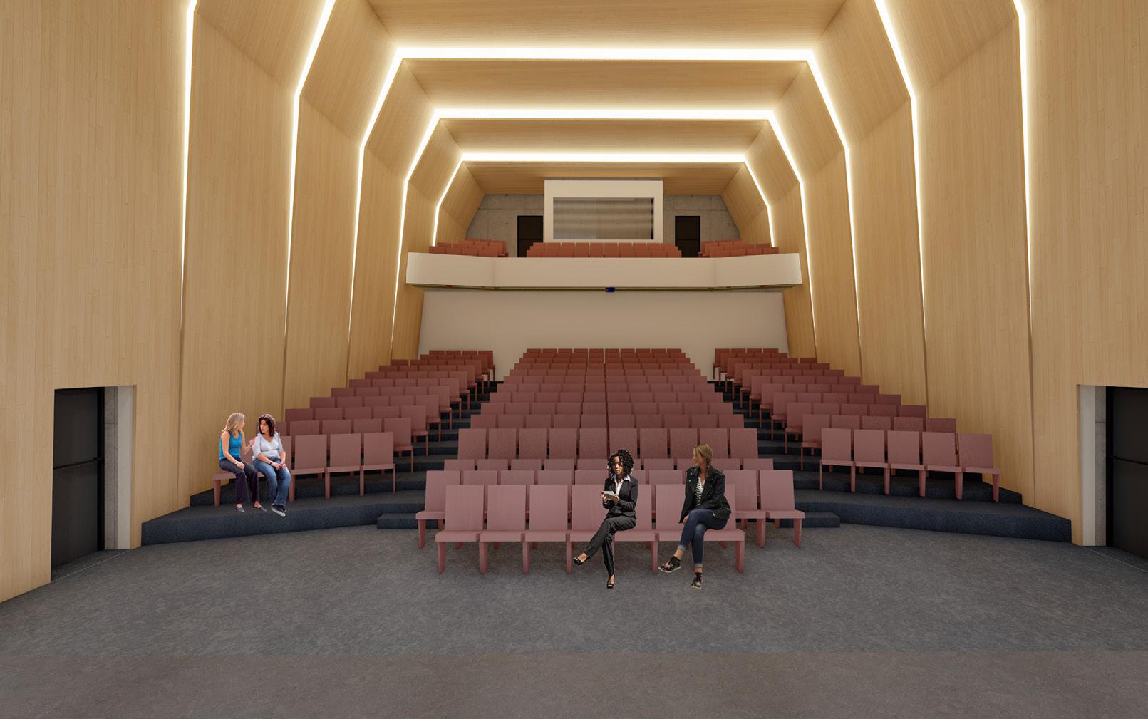
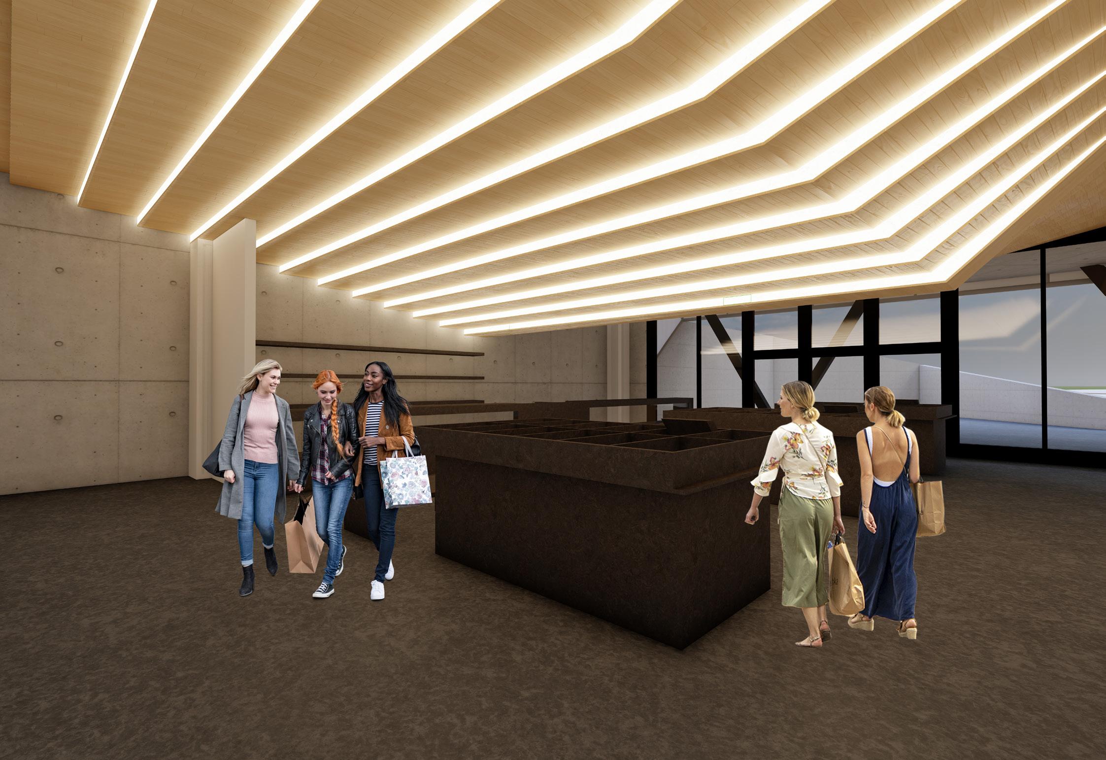
This experience of music is guided by the impacts that concavity and convexity have on acoustics. Wood paneling is arranged in convex shapes within performance halls so performers can gauge the quaility of their music. In other spaces, wood paneling is used in a concave manner to emphasize activity.
LEGEND
Concavity and convexity reflect sound differently. This affect acoustics is translated to spatial and visual applications both interior and exterior.
1 - Performance Hall 2 - Market Space 3 - Exhibition 4 - Library 5 - Restroom 6 - Elevator 7 - Exterior Market Space 8 - Audience Pavilion 9 - Classroom 10 - Rehearsal Room 11 - Storage 12- Exterior Rehearsal
25 Source Concave Convex Source Performance Hall Market Space CONCEPT
CONVEX CONCAVE
Source Source
1 8 2 3 4 5 5 6 7 2 3 4 1 A F B C D E 5 6 7 8 9 G H I 1 1 1 12 5 5 6 10 9 9 9 9 11 11 2 3 4 1 A F B C D E 5 6 7 8 9 G H I 26 Ground Floor
Second Floor
28
29
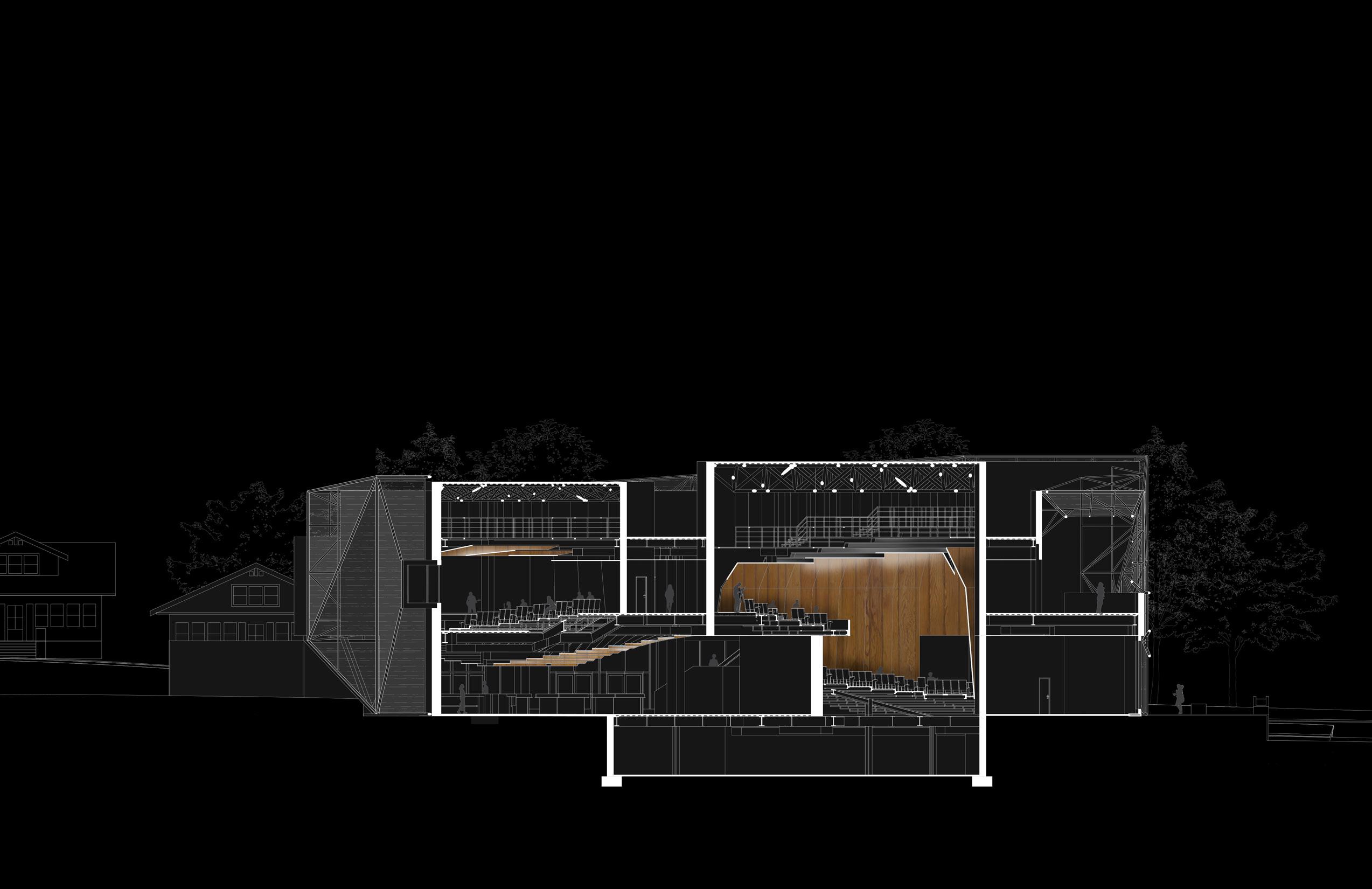
Section B:BB
(Performance Hall Detail and Facade Detail illustrated by Byron Ho)
East Elevation
Section B:BB
FACADE STRUCTURE
FLOOR SLAB
ROOF TOP OF PERFORMANCE
COLUMNS AND BEAMS
FACADE STRUCTURE
SPACE FRAMES
FACADE STRUCTURE
FACADE STRUCTURE
FACADE STRUCTURE
FLOOR SLAB
FACADE STRUCTURE
ROOF TOP OF PERFORMANCE
FACADE STRUCTURE
ROOF TOP OF PERFORMANCE
FLOOR SLAB
ROOF TOP OF PERFORMANCE
FACADE STRUCTURE
FACADE STRUCTURE
ROOF TOP OF PERFORMANCE
SPACE FRAMES
ROOF TOP OF PERFORMANCE
ROOF TOP OF PERFORMANCE
SPACE FRAMES
COLUMNS AND BEAMS
COLUMNS AND BEAMS
ROOF TOP OF PERFORMANCE
ROOF TOP OF PERFORMANCE
SPACE FRAMES
SPACE FRAMES
SPACE FRAMES
FLOOR SLAB
SPACE FRAMES
SPACE FRAMES
FLOOR SLAB
FLOOR SLAB
SPACE FRAMES
FLOOR SLAB
FLOOR SLAB
FLOOR SLAB
FLOOR SLAB
COLUMNS AND BEAMS
FLOOR SLAB
COLUMNS AND BEAMS
FLOOR SLAB
COLUMNS AND BEAMS
FLOOR SLAB
COLUMNS AND BEAMS
COLUMNS AND BEAMS
COLUMNS AND BEAMS
COLUMNS AND BEAMS
FLOOR SLAB
COLUMNS AND BEAMS
FLOOR SLAB
COLUMNS AND BEAMS
COLUMNS AND BEAMS
FLOOR SLAB
FLOOR SLAB
FLOOR SLAB
FLOOR SLAB
FLOOR SLAB
FLOOR SLAB
FLOOR SLAB
COLUMNS AND BEAMS
FLOOR SLAB
COLUMNS AND BEAMS
COLUMNS AND BEAMS
COLUMNS AND BEAMS
COLUMNS AND BEAMS
COLUMNS AND BEAMS
2”
FLOOR SLAB
COLUMNS AND BEAMS
COLUMNS AND BEAMS
COLUMNS AND BEAMS
FLOOR SLAB
FLOOR SLAB
FLOOR SLAB
FLOOR SLAB
FLOOR SLAB
COLUMNS AND BEAMS
FLOOR SLAB
FLOOR SLAB
COLUMNS AND BEAMS
FLOOR SLAB
COLUMNS AND BEAMS
COLUMNS AND BEAMS
COLUMNS AND BEAMS
FLOOR SLAB
COLUMNS AND BEAMS
COLUMNS AND BEAMS
Performance Hall Detail
FLOOR SLAB
COLUMNS AND BEAMS
FLOOR SLAB
FLOOR SLAB
FLOOR SLAB
FLOOR SLAB
FLOOR SLAB
FLOOR SLAB
6” Rigid Insulation 12” Site Cast Concrete 1/2” Metal Plate 7/8” Diameter Bolt 3” Diameter Tubing Brace Aluminumn Glass Retainer Neoprene Glazing Gasket Acoustical 3/8” Lamination Vert Tappered Airspace 1” I.G. 1/4” Lamination 1/2” Airspace 1/4” Lamination Angled MATERIAL CONNECTIONS
STRUCTURE
STRUCTURE
PERFORMANCE FRAMES AND BEAMS AND BEAMS AND BEAMS
OF PERFORMANCE FRAMES SLAB SLAB SLAB SLAB AND BEAMS AND BEAMS AND BEAMS
Stone Ballast
Roof Insulation EDPM Membrane Vapor Retarder Space Frame
Concrete Slab
Concrete Slab
Structural Axon Facade Detail 1”
4”
4”
3”
Depth Steel Corrugated Decking
x 1.75’ HVAC Duct
Depth Steel Joist Drainage
1/8” = 1’-0” 30
1.75’
24”
WALL SECTION D-D
Team: HunTel Engineering Team
Program: Civil Planning
Location: Midwest
Year: Winter 2023 (Completed)
As day to day life sees a continous need for up-to-date communication and connection services, rural areas of the United States look to become current. The team at HunTel Enginneering has dedicated years designing a solution for this goal.
My role in this large scale civil planning project came at the end by analyzing as-built maps for accuracy and translating the information contained in these documents into cloud-based maps. This meant taking physical maps and drafting all contents into an AutoCad file then inputting the same data into a cloud-based catalouge known as “StellaRad.”
In order to check for accuracy, I double-checked the contents of the maps by calculating every individual component and cross referencing with a databook and billing spreadsheet.
As-Built Town Overview
(Plan produced using a combination of AutoCad and StellaRad.)
QUINLAN AVE QUINLAN AVE QUINLANAVE QUINLAN AVE QUINLAN AVE Q U N L A N A V E OAK ST COHWYV48 COHWYV48 CO HWY V48 RUSSELL ST RUSSELL ST ASH ST COUNTRY CLUB DR 2 7 0 T H T R 270TH TRL S G R O V E S T GROVE ST WATER ST US HWY 18 US HWY 18 US HWY 18 US HWY 18 US HWY 18 270TH ST 270TH ST 270TH ST 270TH ST GROVE ST W MA N ST 7 H T R 31
BUTLER CONDUIT
R O A N O K E A V E C L O V E R L N PEARL ST M A T T K E A V E CO HWY V48 CO HWY V48 COHWYV48 N M A D S O N A V E N H A M L T O N A V E R D G W A Y A V CLOVE R DR D A W N A V E RIDGEWAY AVE RIDGEWAY AVE S JACKSON AVE N JEFFERSON AVE N O R T H E A S T A V E N WASHINGTON AVE S WASHINGTON AVE S W A S H N G T O N A V E 270TH ST S MADISON AVE N WOODWARD AVE PLUM ST S JEFFERSON AVE S JEFFERSON AVE WESLEY ST N J A C K S O N A V E N J A CK S O N A VE E MA N ST B R C H D R R O A N O K E A V E SCHULT RIDGE RD E HIGH ST E H GH ST D R E W E L O W A V E MECHAN C ST S O U T H E A S T A V E S O U T H E A S T A V E WEST AVE E RA LROAD ST E RA LROAD ST W HIGH ST W M LL ST US HWY 18 E MILL ST E MILL ST N WASHINGTON AVE N WASHINGTON AVE L ONS RD NJACKSONST NJACKSONST F A L C O N D R 270TH ST 270TH ST C O H W Y V 4 8 C O H W Y V 4 8 C L O V E R C R US HWY 18 D R E W E L O W A V E S O U T H E A S T A V E S JEFFERSON AVE E MA N ST W MA N ST WESLEY ST L ONS RD 270TH ST C O H W Y V 4 8 CO HWY V48 CO HWY V48 CO HWY V48 B R C H D R PLUM ST WESLEYST R D G W A Y A V S O U T H E A S T A V E N J A CK S O N A VE N WASHINGTON AVE VINEYARDLANE BUCKEYE ST 32
Town Map: All houses and buidlings contain data that has been input into StellaRad and accounted for in a spreadsheet and databook verified by me. N
33
HAMILTON AVE
JEFFERSON AVE
WASHINGTON AVE
WASHINGTON AVE
WOODWARD AVE PLUM ST AVE
HIGH ST
MILL ST N
JEFFERSON AVE
MAIN ST
MAIN ST 270TH ST CO HWY V48 CO HWY V48
WASHINGTON AVE
N
N
S
N
W
W
S
E
W
N
34 N MADISON AVE S JACKSON AVE NORTHEAST AVE 270TH ST S MADISON AVE N JACKSON AVE E MAIN ST E HIGH ST E HIGH ST D R E W E L O W A V E S O U T H E A S T A V E E RAILROAD ST E RAILROAD ST US HWY 18 E MILL ST E MILL ST D R E W E L O W A V E S O U T H E A S T A V E CO HWY V48 PLUM ST T A V E
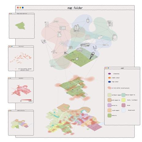
INTERPOSE
Team: Jesus Perez-Cortez, Sahr Qureishi, Madeline McGill
Program: Greenhouse, Mediateque, Incubator, Kitchen, Dining
Location: Omaha, NE
Year: Fall 2020
Course: Dsgn 410 - Collaborate - Salvador Lindquist
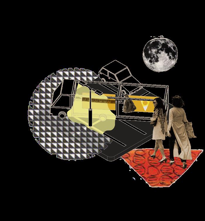
Interpose is a discovery of the inter and disconnected experiences found revolving around food insecurity within and around the realm of secondary education. It is an exploration of students and their daily itineraries and experiences. It is a conscious effort to bring hidden truths to visibility while highlighting a network of converging and diverging human experiences. It is a break from the rigidity of the school system and structure to articulate the notion of a network components and thresholds. The network and threshold are never fully stagnant but are in a state of being, where being is nothing more than the process of becoming.
Interpose is fluid to external parameters and users. The design provides a site with spaces, amenities, and fleets focusing on the pervasive issue of food insecurity allowing students access to healthy foods, social engagement, build cooking skills, transportation, awareness, and knowledge.
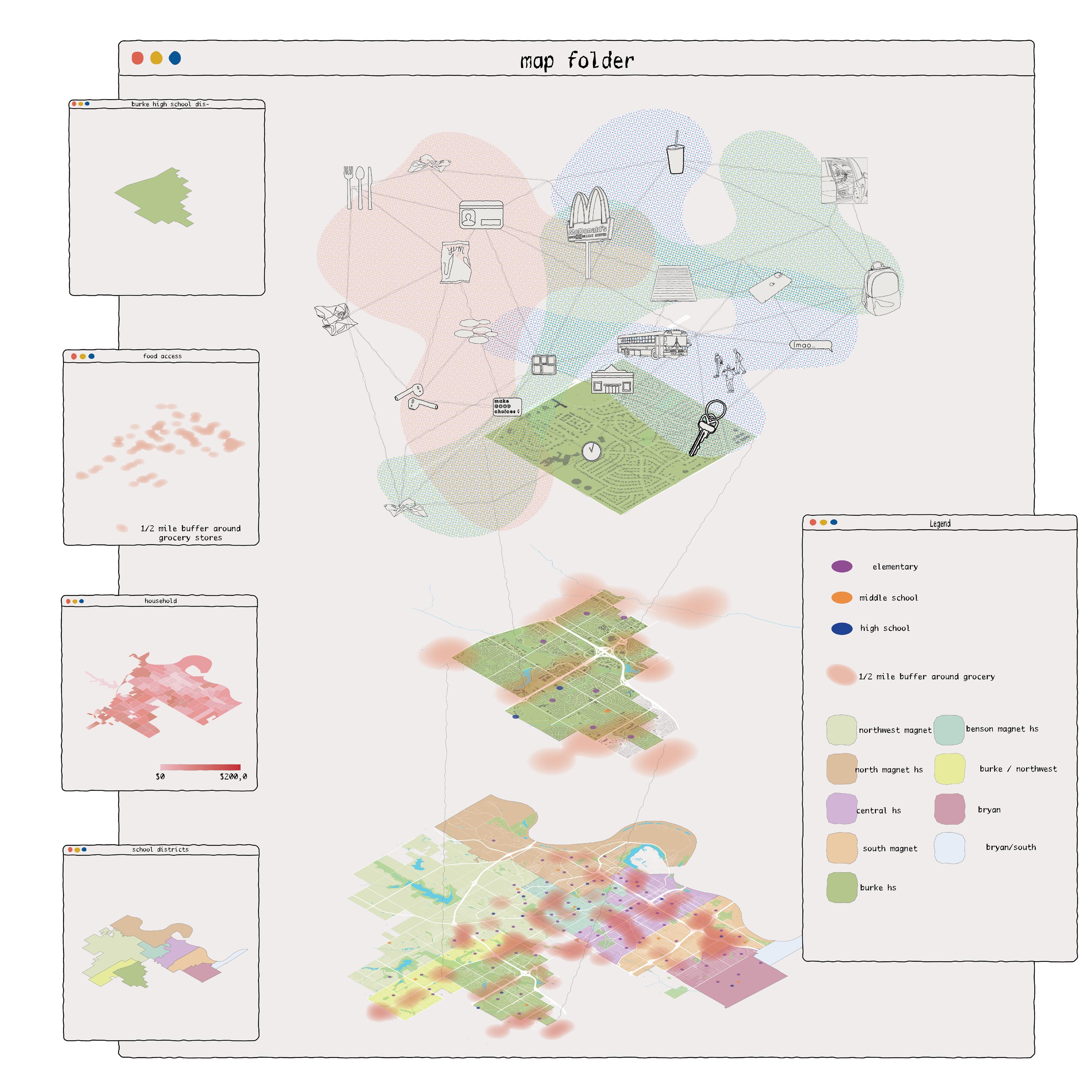
Millieu Network Map
(Image produced using Rhino 3D, Illustrator, and ArcGIS.)
35
36

Threshold: A threshold separates opportunity and understanding. It must be acknowledged to be broken.

Exhibition: Raises awareness to people who do not experience or are not aware of food insecurity.

Invitation: Breaks those who experience and those who do
Cars: Mobile Exhibition
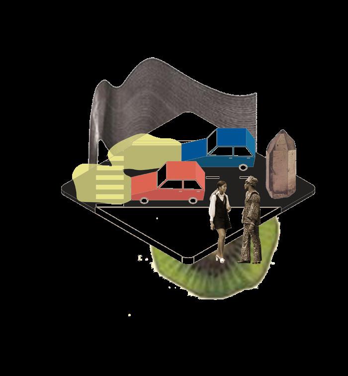
Semi-truck: Mobile Exhibition
The network converges on the site and diverges across the city through a series of programmatic fleets which serve as nodes of exhibition, invitation, and cultivation. There is a disparity of opportunity and understanding created by a threshold of those who experience food insecurity and those who do not.
Top Row: Vignettes
Bottom Row: Fleets
Bus: Invitation

37

the threshold from experience food insecurity not.

Cultivation: Physically addresses food insecurity through greenhouses, gardens, kitchens, and food trucks.
Convergence: People and experiences meet and dynamically engage with one another on the site.
Food Truck: Incubator Cultivation
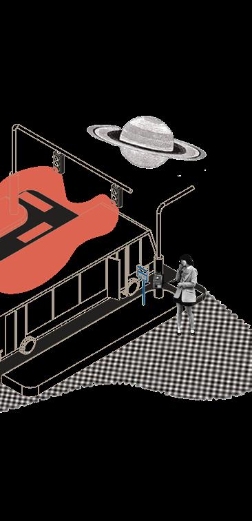
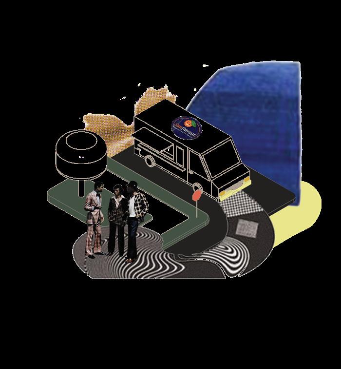
The fleets are pollinators of the network. Blending into the vehicular landscape but also intruding on settings and situations in a way that draws attention to itself and its agencies. The fleets are divided into 5 categories, all serving a different purpose within the network. The categories vary in scale and in intervention.
U-Haul Truck: Resource Cultivation

38

The site is located at an intersection of secondary education, food access, and transportation in downtown Omaha. The main connection point utilized is Central High School and a local food bank as well as the downtown Omaha district.
39
Above: Site Analysis
40 Second Floor Ground Floor A B BB AA

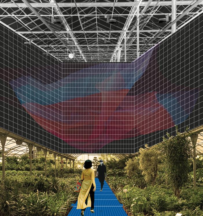
The threshold canopy is the physical manifestation of the threshold and network. Rather than separating needs and users, it serves to connect the greenhouses and their programs. It formulates a visual and habitable connection on the site by way of the social and physical fabric that is fluid and never stagnant.
41
Above: Elevations South Elevation East Elevation
42
Above: Sections
Section A:AA Section B:BB
43
Above: Plan Oblique
Page 44: Exploded Axon
44
Mesh Canopy
Posts Upper Deck
Dining 2nd Floor
Incubator 2nd Floor
Roofs
Food Truck Plaza
Promenade Fleets
Greenhouses
Orchard Gardens Green-beds
Central Parking Garage
ADDITIONAL PROJECTS

45
Boca Del Rio, MX (Photograph)
Portrait (Acrylic Painting)
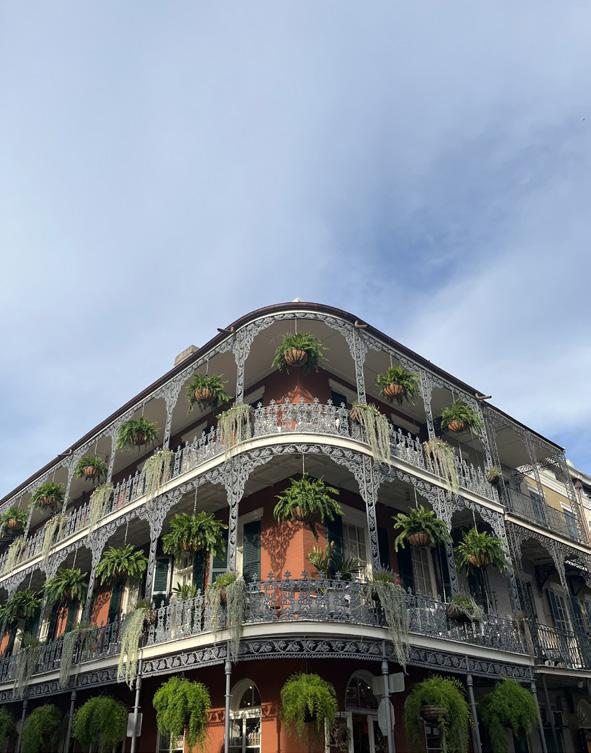
New Orleans, LA (Photograph)

Diameter - 1'-0" Jack Rafter Size: 2" x 6" NEW JOISTS 2 - 2" x 12" 6" x 6" @ 6'-7" @ O.C. EXISITING POSTS RETAINING WALL PROPOSED 4/12" PITCH NEW DECK COVER 4/12" PITCH NEW DECK COVER 12 4 NEW POST 6" x 6" 2 - 2" x 12" NEW JOISTS EXISITING BEAM 2- 2" x 12" 6" x 6" @ 6'-7" @ O.C. EXISITING POSTS RAILING EXISITING JOISTS 2" 12" @ 16 O.C. RETAINING WALL 4 12 6" x 6" NEW POST RAILING 2- 2" x 12" EXISITING BEAM 3313 CHERRY LN, BELLEVUE, NE 68147 ELEVATIONS 3786 SF TOTAL IMPERVIOUS COVERAGE: SITE INFORMATION SIZES EXISITING JOISTS 2" 12" @ 16 O.C. A102 Title Sheet Number 60’ 45’ 30’ 15’ 10’ 5’ 0’ 46 S-33 GREENE COUNTY T-83N 12TH ST STATE HWY 144 Y W 7TH T-83N GREENE COUNTY T-83N GREENE COUNTY GREENE COUNTY S-4 GREENE COUNTY S-4 GREENE COUNTY R-29W UNTY H GREENE COUNTY R-29W GREENE COUNTY T-83N GREENE COUNTY S-5 GREENE COUNTY T-83N R-29W GREENE COUNTY T-84N GREENE COUNTY T-83N GREENE COUNTY R-29W GREENE COUNTY R-29W R-29W GREENE COUNTY Hardcorist Architecton Hacked Generative Codes Monolith Bath House Found Objects Residential Deck Cover Jefferson Conduit Design