DIFFRACTION DIFFRACTION JESUS PEREZ-CORTEZ BYRON HO JESUS J. PEREZ-CORTEZ Architecture Portfolio + CV
Omaha, NE 68108 | 4029834754 | jesusperez123.jc@gmail.com | WWW: Bold Profile
Omaha, NE 68108 4029834754 jesusperez123.jc@gmail.com WWW
Omaha, NE 68108 | 4029834754 | jesusperez123.jc@gmail.com | WWW: Bold Profile

Professional Summary
Professional Summary
Professional Summary
Professional Summary
Detail-oriented team player with strong organizational skills. Ability to handle multiple projects simultaneously with a high degree of accuracy.
Detail-oriented team player with strong organizational skills. Ability to handle multiple projects simultaneously with a high degree of accuracy.
Detail-oriented team player with strong organizational skills. Ability to handle multiple projects simultaneously with a high degree accuracy.
Detail-oriented team player with strong organizational skills. Ability to handle multiple projects simultaneously with a high degree of accuracy.
Languages
Languages
Languages
Languages
English
English
English
Spanish Skills
English Spanish
Spanish
Spanish Skills
Skills
Skills
Architecture and Design
Architecture and Design
Architecture and Design
3D Modeling and Visualization
Design Research and Development
Design Research and Development
Construction Documentation
Team Collaboration
Team Collaboration
Software
Software
Software
Design Research and Development
Software
Design Research and Development
Architecture and Design Construction materials
Construction materials
Team Collaboration
Construction materials
3D Modeling and Visualization
3D Modeling and Visualization
3D Modeling and Visualization
Concept Development
Team Collaboration Construction documentation
Construction documentation
Construction documentation
Adobe Creative Suite Rhinoceros 3D | Lumion | Enscape | AutoCad Grasshopper
Adobe Suite | Rhinoceros 3D | Lumion | Enscape | AutoCad Grasshopper
Adobe Suite | Rhinoceros 3D | Lumion Enscape AutoCad | Grasshopper
Adobe Suite | Rhinoceros 3D | Lumion Enscape | AutoCad Grasshopper
Work History
Architectural Designer - 2 yrs 3 mos
Work History
Architectural Designer - 2 yrs 3 mos
Architectural Designer - 2 yrs 3 mos
Consultant - Omaha, NE
01/2022 - Current
Consultant - Omaha, NE
Architectural Designer - 2 yrs 3 mos
Consultant - Omaha, NE
Collaborated with multidisciplinary teams to create functional, efficient, and visually appealing spaces for clients.
Consultant - Omaha, NE
Collaborated with multidisciplinary teams to create functional, efficient, and visually appealing spaces for clients.
Increased client satisfaction by consistently delivering high-quality designs that met or exceeded expectations.
01/2022 - Current
01/2022
01/2022 - Current
Collaborated with multidisciplinary teams to create functional, efficient, and visually appealing spaces for clients.
Collaborated with multidisciplinary teams to create functional, efficient, and visually appealing spaces for clients.
Increased client satisfaction by consistently delivering high-quality designs that met or exceeded expectations.
Increased client satisfaction by consistently delivering high-quality designs that met or exceeded expectations.
Developed comprehensive construction documents to ensure accurate execution of architectural concepts during the building process.
Increased client satisfaction by consistently delivering high-quality designs that met or exceeded expectations.
Developed comprehensive construction documents to ensure accurate execution of architectural concepts during the building process.
Developed comprehensive construction documents to ensure accurate execution of architectural concepts during the building
Huntel Engineering - 1 yr 1 mo
Developed comprehensive construction documents to ensure accurate execution of architectural concepts during the building process.
Huntel Engineering - 1 yr 1 mo
Civil Planning Drafter - Blair, NE
Huntel Engineering - 1 yr 1 mo
03/2023 - Current
Huntel Engineering - 1 yr 1 mo
Civil Planning Drafter - Blair, NE
Collaborated with engineers to develop accurate and detailed construction documents for 7 projects.
Civil Planning Drafter - Blair, NE
Collaborated with engineers to develop accurate and construction documents for 7 projects.
03/2023 - Current
Civil Planning Drafter - Blair, NE 03/2023
Collaborated with engineers to develop accurate and detailed construction documents for 7 projects.
Collaborated with engineers to develop accurate and detailed construction documents for 7 projects.
Contributed in reducing errors during before and after construction phase by meticulously reviewing drawings for consistency and accuracy.
03/2023 - Current
Contributed in reducing errors during before and after construction phase by meticulously reviewing drawings for consistency and accuracy.
Evaluated information provided by engineers to create accurate drawings according to measurements and specifications.
Contributed in reducing errors during before and after construction phase by meticulously reviewing drawings for consistency accuracy.
Evaluated information provided by engineers to create accurate drawings according to measurements and specifications.
Contributed in reducing errors during before and after construction phase by meticulously reviewing drawings for consistency and accuracy.
Evaluated information provided by engineers to create accurate drawings according to measurements and specifications.
Hensel Richards Constructors - 4 yrs 2 mos
Evaluated information provided by engineers to create accurate drawings according to measurements and specifications.
Exterior Plasterer - Omaha, NE
Hensel Richards Constructors - 4 yrs 2 mos
Hensel Richards Constructors - 4 yrs 2 mos
05/2017 - 07/2021
Hensel Richards Constructors - 4 yrs 2 mos
Increased client satisfaction with exceptional attention to detail and adherence to design specifications.
Exterior Plasterer - Omaha, NE
Exterior Plasterer - Omaha, NE
Enhanced the durability of building exteriors by applying high-quality plastering techniques on over 15 projects.
Increased client satisfaction with exceptional attention to detail and adherence to design specifications.
05/2017 - 07/2021
Exterior Plasterer - Omaha, NE 05/2017
Increased client satisfaction with exceptional attention to detail and adherence to design specifications.
Reduced project completion times by efficiently managing multiple exterior plastering tasks simultaneously.
05/2017 - 07/2021
Enhanced the durability of building exteriors by applying high-quality plastering techniques on over 15 projects.
Increased client satisfaction with exceptional attention to detail and adherence to design specifications.
Education
Enhanced the durability of building exteriors by applying high-quality plastering techniques on over 15 projects.
Reduced project completion times by efficiently managing multiple exterior plastering tasks simultaneously.
Enhanced the durability of building exteriors by applying high-quality plastering techniques on over 15 projects.
Reduced project completion times by efficiently managing multiple exterior plastering tasks simultaneously.
Reduced project completion times by efficiently managing multiple exterior plastering tasks simultaneously.
Education
Education
Bachelor of Science: Architecture
05/2021
Education
University of Nebraska - Lincoln - Lincoln, NE
Bachelor of Science: Architecture
Bachelor of Science: Architecture
Minor in Product Design
05/2021
Bachelor of Science: Architecture
Dean's List [Fall 2020]
University of Nebraska - Lincoln - Lincoln, NE
University of Nebraska - Lincoln - Lincoln, NE
05/2021
University of Nebraska - Lincoln - Lincoln, NE
Minor in Product Design
Minor in Product Design
Extracurricular Activities: Co-President of National Organization of Minority Architects
Minor in Product Design
Dean's List [Fall 2020]
Dean's List [Fall 2020]
Extracurricular Activities: William H. Thompson Scholar
Extracurricular Activities: Co-President of National Organization of Minority Architects
Dean's List [Fall 2020]
High School Diploma
Extracurricular Activities: Co-President of National Organization of Minority Architects
Extracurricular Activities: Member of Student Advisory Board for College of Architecture
Extracurricular Activities: Co-President of National Organization of Minority Architects
Extracurricular Activities: Member of Student Advisory Board for College of Architecture
Omaha South High School - Omaha, NE
Omaha South High School - Omaha, NE
Extracurricular Activities: William H. Thompson Scholar
Extracurricular Activities: William H. Thompson Scholar
Extracurricular Activities: Member of Student Advisory Board for College of Architecture
Extracurricular Activities: William H. Thompson Scholar
4.3 GPA
05/2017
05/2017


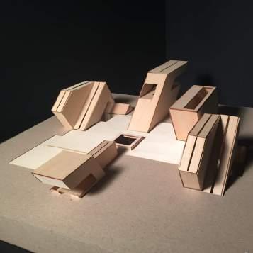
Program: Makerspace, Art Studio, Communal Living
Location: Detroit MI
Year: Spring 2020
Course: Arch 311 - Situate - Ellen Donnelly
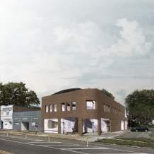
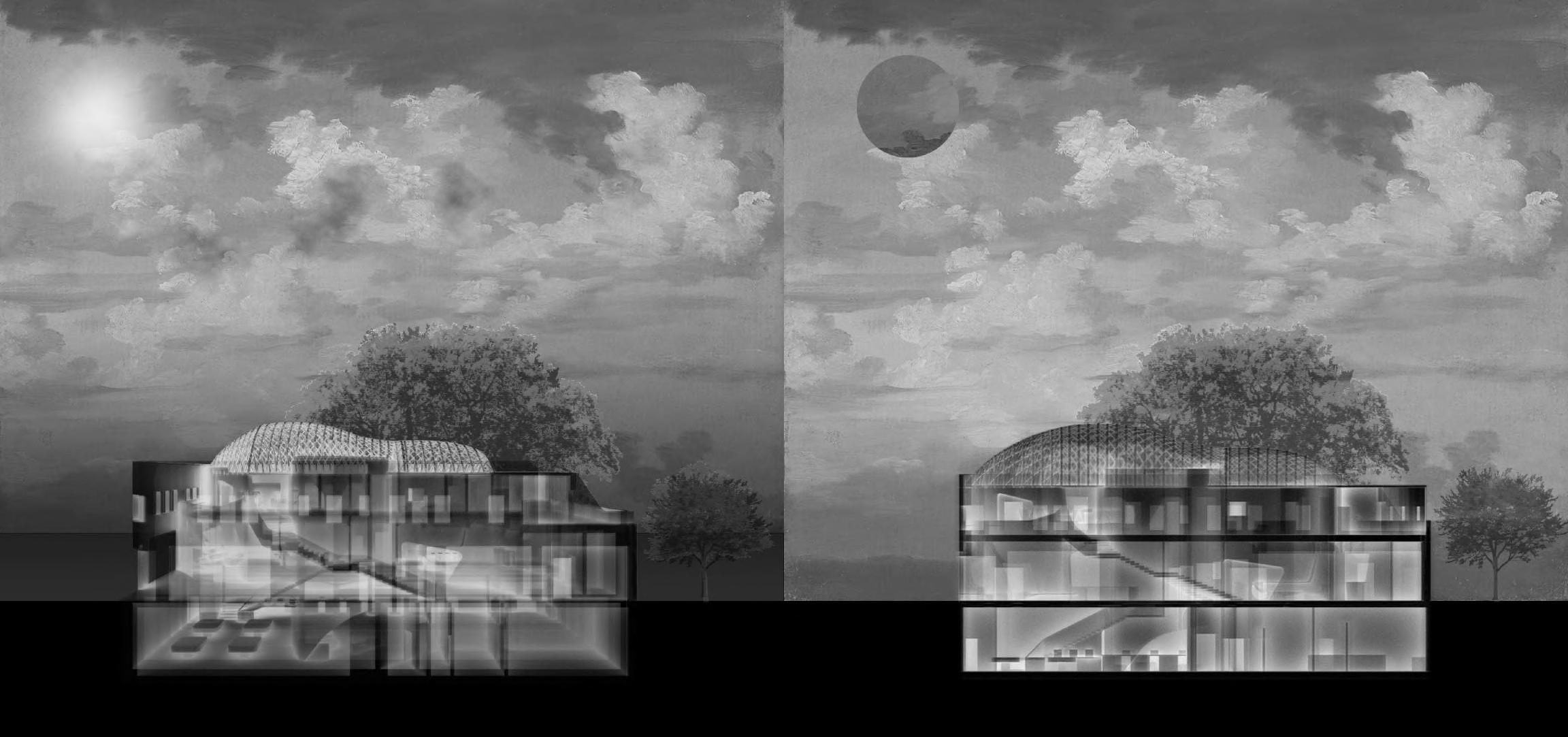
Located within the East Warren neighborhood of Detroit, MI, The Hermit Crab inhabits the shell of a building no longer there. By offering a makerspace, art studio, and communal living, the community of East Warren is presented with opportunities to collaborate, explore, and learn from each other to foster a network of makers, artists, and residents.
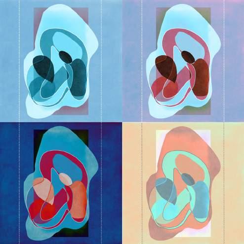
The design is driven by the idea that the building appears to be moving in tandem with the user. This is achieved through the use of malleable surfaces that morph to way suggest changes in motion and activity. The topography of the floors, walls, and ceilings are used to achieve this goal. The design asks occupants to explore the interior and exterior spaces within the shell. The skin of The Hermit Crab is scaled with metallic plates that display an iridescent reflection and aids in contouring the form. The spaces advocate for social encounters among peers and physical interactions with the building itself.
Exterior Render
(Image produced using a combination of Rhino 3D, Lumion, and Photoshop.)
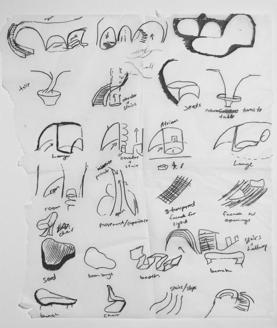
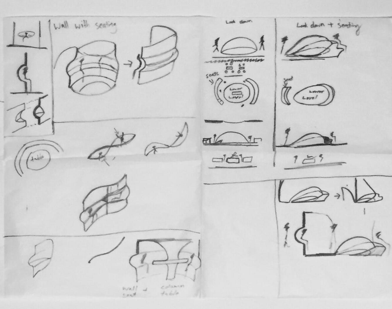

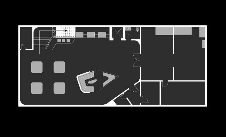
The drawings shown explore horizontal and vertical qualities of experience to inform the organization of spaces. Such qualities include: intersection, voids, boundaries, circulation, light, and time spent in spaces. There were also various ideas of how surfaces would move and morph. These investigations laid the ground work and were taken as precedents for the design.
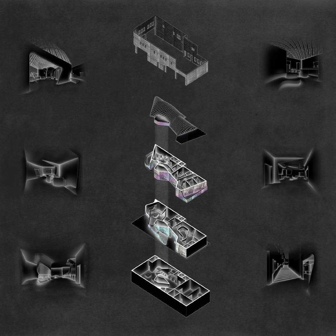
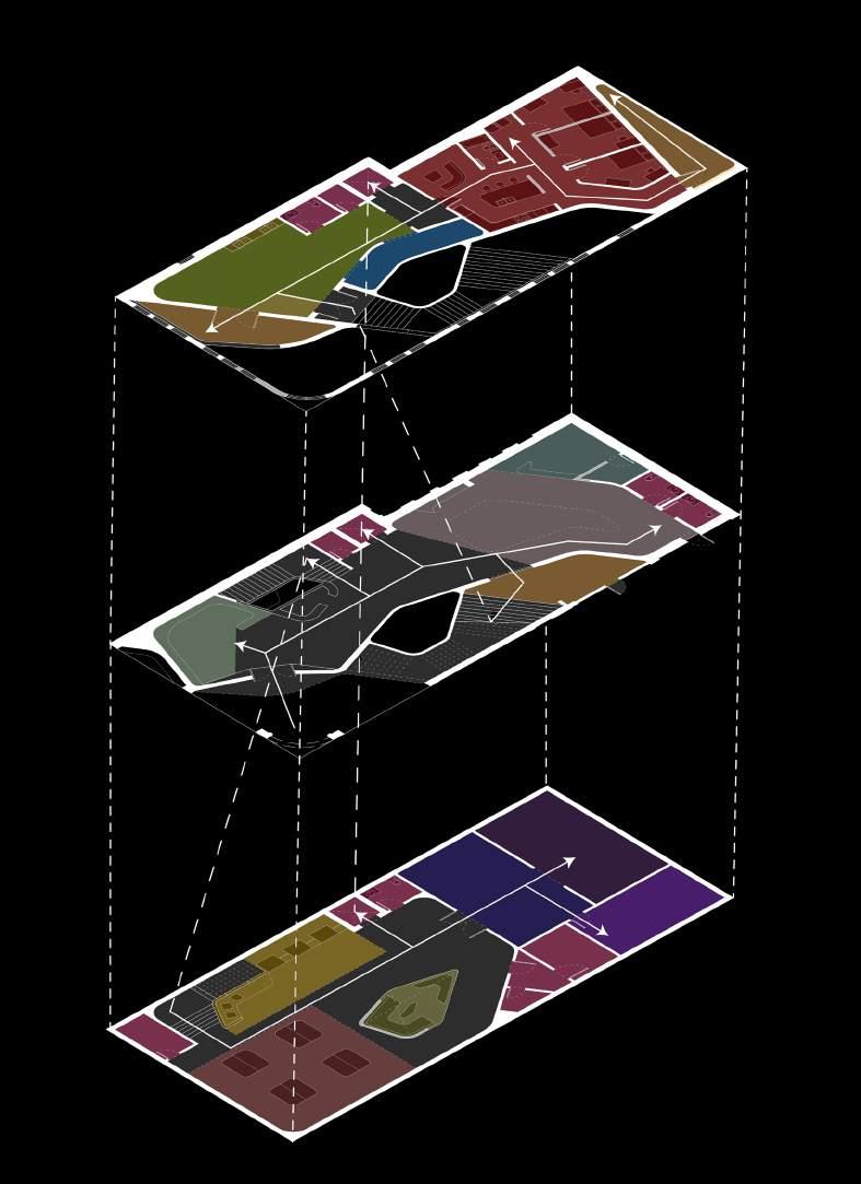
On the ground floor, users are provided with a lounging space as well as a small coffee shop. Occupants are presented with the option to follow the exterior stairs up to the second floor housing the art studio and communal living or follow the stairs down leading to the makerspace.
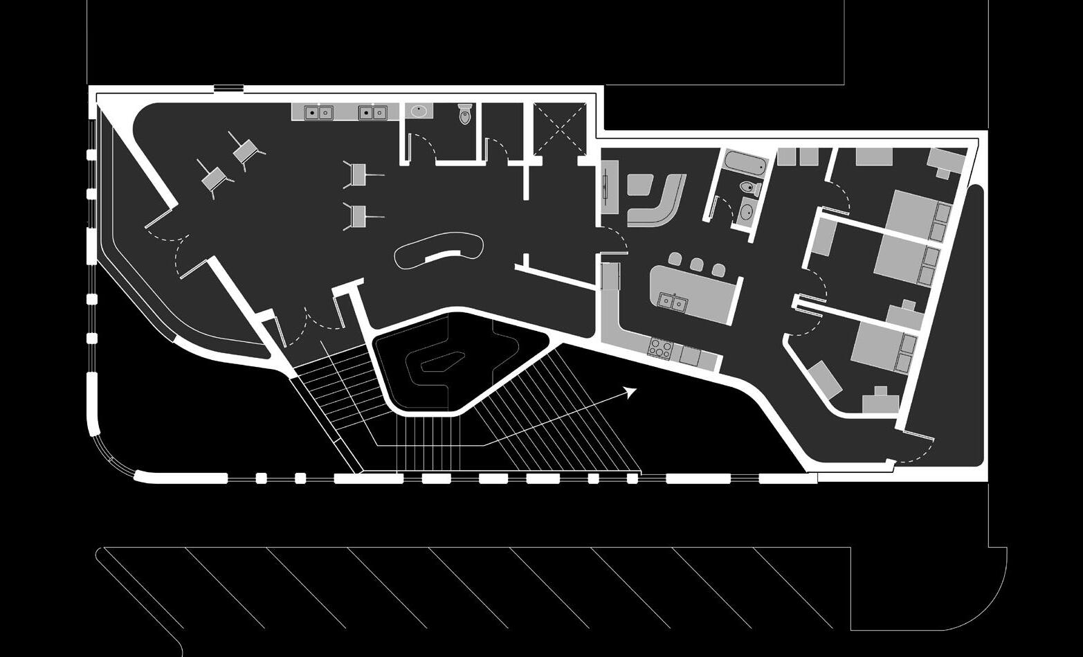
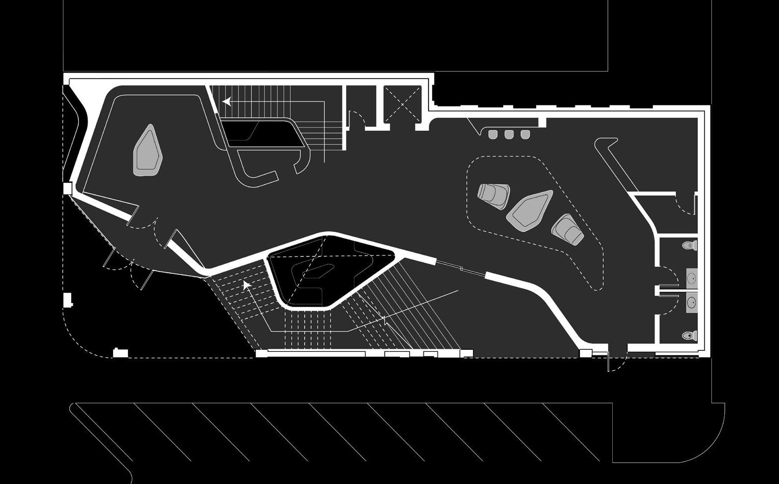
On the top floor, the art studio, gallery, and living room are filled with natural light that filters through the curved glass roof and truss frame structure. The lounge in the makerspace is emphasized with the natural light captured up by the glass roof. This allows for a change in scale and an experiential moment.
Collaborators:
Tim Murphy - Structural Engineer- Wilson & Company, Inc, Jose Ochoa - Contractor - J Builds LLC
Program: Master Bedroom, Bathroom, Closet
Location: Omaha, Nebraska
Year: Summer 2023 (In Progress)
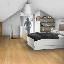
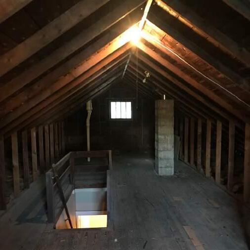
Located in the Historic Benson neighborhood of Omaha, NE, this design focuses on modifying an existing element into a space that provides convenience.
There was an emphasis on effectively utilizing as much space as possible, this goal even extended as far as to taking advantage of the spacing between studs in the existing knee walls. In the end, project resulted in a Master Bedroom with a bathroom, two closets, and built-in drawers offering the client functionality and comfort.
Throughout the duration of the project, I acted as the architectural designer, consultant, and coordinator. Not only did I design the conversion but I also worked alongside the client to indentify what problems needed solving. I provided multiple iterations of possible outcomes. I collaborated with the Structural Engineer in ensuring the structural integrity of the project. Finally, I acted as the main point of contact for the contractor to direct any questions and additional information requests for the project.
This project provided challenging obstacles and a valuable learning experience. It was accomplished through the collaborative efforts of all parties involved.
Proposal Bedroom Perspective
(Image produced using a combination of Rhino 3D and Photoshop.)

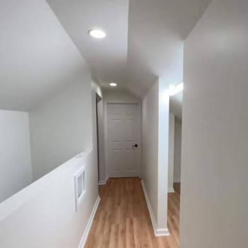
An issue the client wished to address was the lack of space in their room which led them to use a spare room for clothing storage and their vanity. Though a solution to this obstacle could have been to extend the bedroom into their office, it was not ideal for the needs and comfort for the client.
EXISTING 2” x 4” - 24“ O.C. RAFTERS
EXISTING 2” x 4” - 24“ O.C.
FLASHING
GUTTERS
EX. 1” x 8” FASCIA
EX. 3/8” SOFFIT
EX. HARDBOARD SIDING
R- 13 INSULATION
EX. LATH AND PLASTER
1. Existing Roof Rafters 2” x 4” @ 24” O.C. will be sistered using 2” x 6” Joists.
1. Existing Floor Joists are 2” x 6” @ 16” O.C.
2. Existing Knee Wall Studs will remain in place.
2. Existing Roof Rafters are 2” x 4” @ 24” O.C.
3. Existing Windows are both 2’-6” x 2’-6” and will be replaced with new ones of similar dimensions.
EX. 2” x 4” - 24” O.C.
3. Existing Knee Wall Studs are 2” x 4” @ 24” O.C.
4. Existing Windows are both 2’-6” x 2’-6” and will be replaced with new ones.
(SEE DETAILS FOR REWORK, WHERE REQUIRED)
4. Existing Plumbing Pipes will not be rerouted and will be framed around.
5. Existing Plumbing pipes will not be rerouted.
5. Existing Trap Door will be replaced with a new door.
6. Existing Trap Door Will be replaced with a new door.
6. Half Wall will measure a height of 3’- 6”.
7. Existing Closet will be removed.
7. Restroom Door will have width of 32”.
8. Existing Stairs will be grandfathered in.
8. Existing Stairs will be grandfathered in.
9. Existing wood is assumed to be DF-LARCH, No. 2 and better.
10. New wood shall meet or exceed the following:
From NDS NATIONAL DESIGN SPECIFICATION for wood construction using DF-LARCH as a basis
F = 900 psi
F = 575 psi
F = 180 psi
F = 625 psi
F = 1350 psi
E = 1300000 psi
EX. 2” x 4” 16” O.C.
6
1. Existing Roof Rafters 2” x 4” @ 24” O.C. will be sistered using 2” x 6” Joists.
2. Existing Knee Wall Studs will remain in place.
3. Existing Windows are both 2’-6” x 2’-6” and will be replaced with new ones of similar dimensions.
4. Existing Plumbing Pipes will not be rerouted and will be framed around.
5. Existing Trap Door will be replaced with a new door.
6. Half Wall will measure a height of 3’- 6”.
7. Restroom Door will have width of
8. Existing Stairs will be grandfathered in.
#5 REBAR @ 40” O.C. 13 COURSES 8” CONC. BLOCK
2. Existing Roof Rafters are 2” x 4” @ 24” O.C.
3. Existing Knee Wall Studs are 2” x 4” @ 24” O.C.
4. Existing 2” x 6” Joists @ 16” O.C. will be sistered with addtional 2” x 6” Joist
EXISTING 2” x 4” ROOF RAFTERS @ 24” O.C.
Sistered Joists will extend from INTERIOR LOAD BEARING WALL to EXTERIOR LOAD BEARING WALL with the BOX BEAM to provide additional
6. TWIST STRAPS will be used to attach every sistered joist to box beam. 5. Box Beam will be supported with a NEW 4” x 4” Column down to the Basement. The other side will be supported by converting the existing window into load bearing and weight will be distributed down to the foundation wall.
EXISTING 2” x 4” KNEE WALL STUDS @ 24” O.C.
7. 1/2” PLYWOOD SHEETS will be fastened using screws and wood glue. Seams will on the front will alternate from the ones on the back.
PLYWOOD will be APA Rated Structural 1
NEW 2 - 2” x 12” HEADER OVER WINDOW
NEW 2 - 2” x 4” JACK STUDS Jack
8. 2” x 4” HEADERS will be placed 2’-0” from the floor.
EXISTING 2” x 4” KNEE WALL STUDS @ 24” O.C.
EXISTING 2” x 4” ROOF RAFTERS @ 24” O.C.
1/2” PLYWOOD APA RATED STRUCTURAL SHEATHING, BOTH SIDES
EXISTING 2” x 4” ROOF RAFTERS WITH 2” x 6” SISTERED ADDED @ 24” O.C.
EXISTING 2” x 4” KNEE WALL STUDS @ 24” O.C.
Structural Axon
The existing joists in the attic were 2x8’s @ 24” O.C. while the rafters were 2x4 ‘s @ 24” O.C. In order to make the bedroom structurally sound, all joists and rafters were sistered. However, it would not be enough, at which point the Structural Engineer joined to redesign a knee wall into a box beam.
(DET. 1-1 & DET. 2-2 engineered by Tim Murphy - Structural Engineer) Details illustrated by me.
SEE KEYED NOTES. SHEET A 105
1. Convert Existing Knee Wall into BOX BEAM (living room side only).
2. Existing Roof Rafters are 2” x 4” @ 24” O.C.
3. Existing Knee Wall Studs are 2” x 4” @ 24” O.C.
4. Existing 2” x 6” Joists @ 16” O.C. will be sistered with addtional 2” x 6” Joist
NEW 4” x 4” COLUMNS: NEW 4” x 4” COLUMNS:
A107: DET. 1-1 - Box Beam
Sistered Joists will extend from INTERIOR LOAD BEARING WALL to EXTERIOR LOAD BEARING WALL with the BOX BEAM to provide additional
6. TWIST STRAPS will be used to attach every sistered joist to box beam. 5. Box Beam will be supported with a NEW 4” x 4” Column down to the Basement. The other side will be supported by converting the existing window into load bearing and weight will be distributed down to the foundation wall.
7. 1/2” PLYWOOD SHEETS will be fastened using screws and wood glue. Seams will on the front will alternate from the ones on the back.
PLYWOOD will be APA Rated Structural 1
8. 2” x 4” HEADERS will be placed 2’-0” from the floor.
A108: DET. 2-2 - Box Beam
DET. 1-1
x 4” ROOF RAFTERS @ 24” O.C. WITH SISTERED 2’ x 6”
DETAIL SCALE: 1/2” = 1’- 0”
SEE KEYED NOTES. SHEET A 105 and DET. 3-3 on SHEET A 111
DET. 2-2
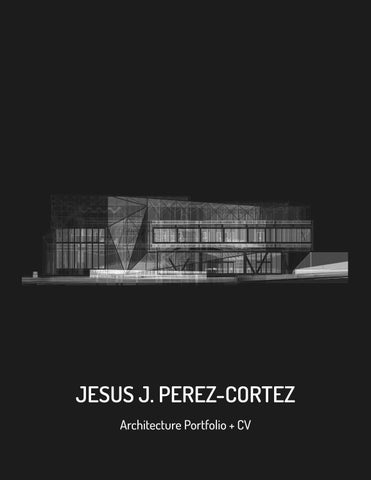
Team: Jesus Perez-Cortez, Byron Ho
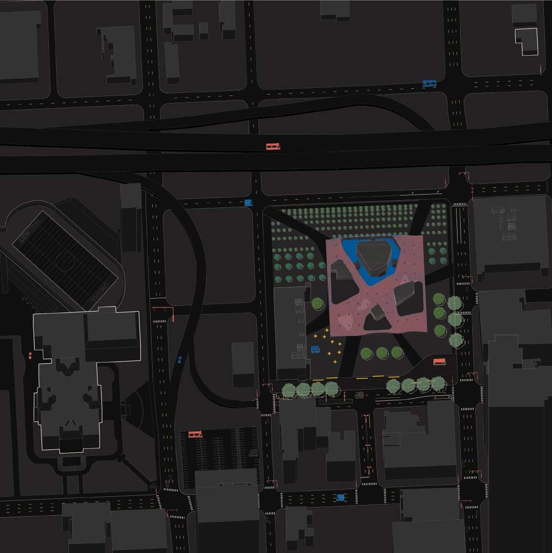
Program: Music Hall, Classroom, Market Space
Location: Omaha, NE
Year: Spring 2021
Course: Arch 411 - Integrage - Mark Heir, Ashley Byars
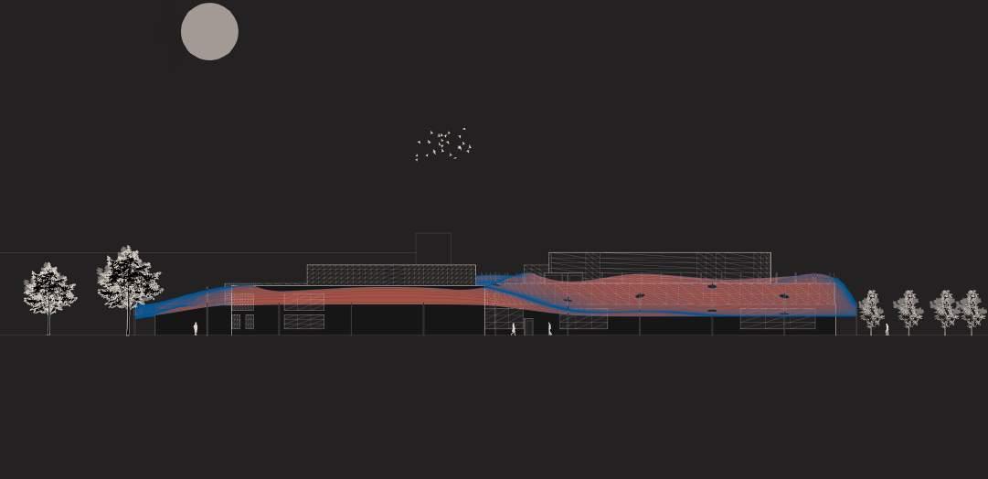
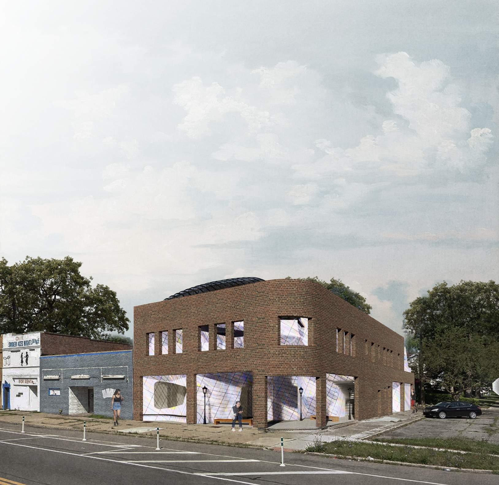
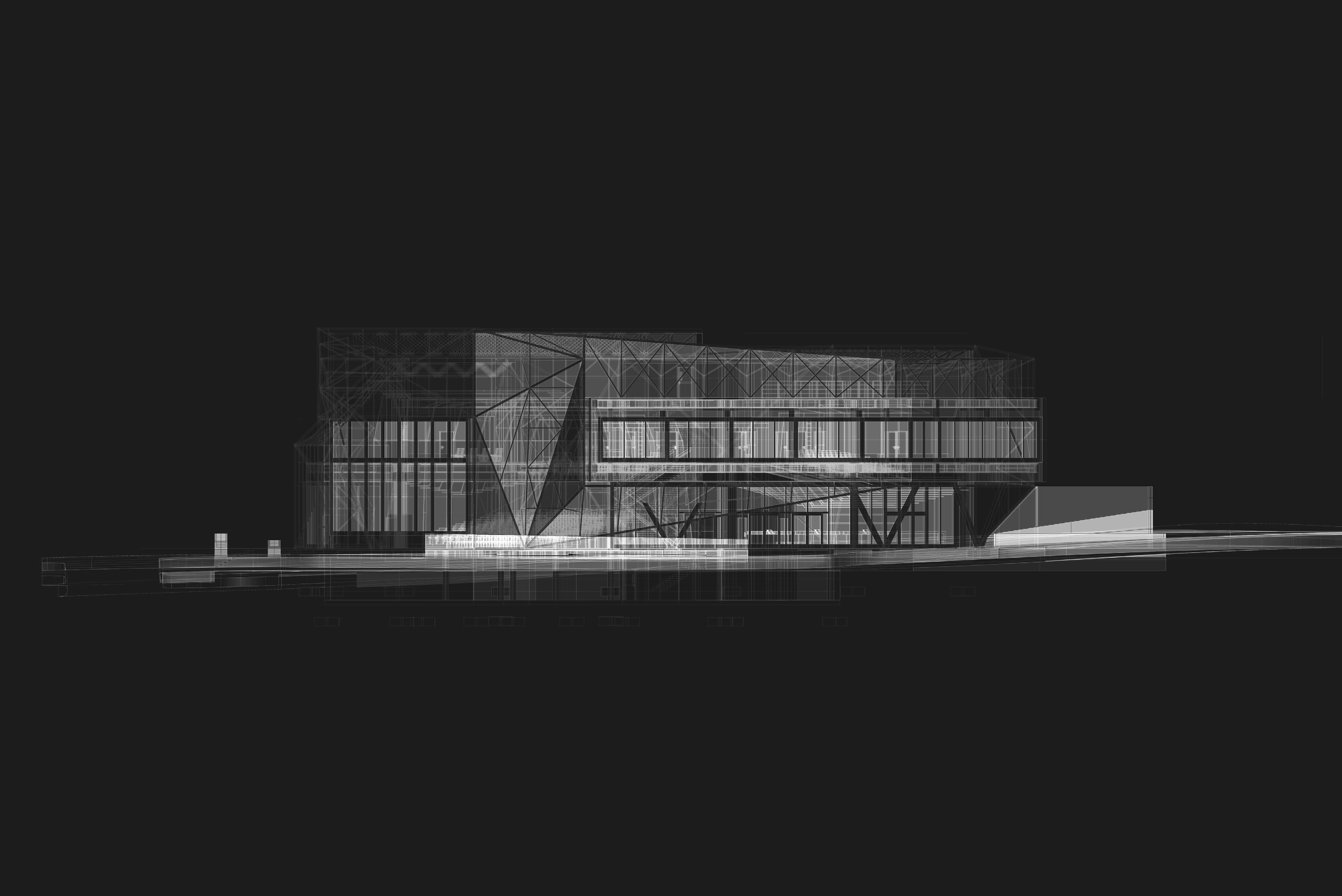
Benson Music Center is dedicated to the experience of music within the Benson Community. By taking the logistics of the affects concave and convex surfaces have on sound, this idea is expressed through materials and surfaces as much as exterior and interior relationships.
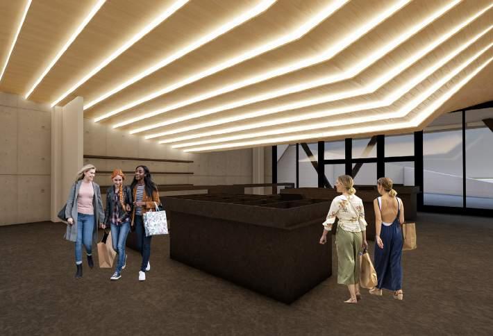
Within the Benson Music Center, music is experienced through performance, education, rehearsal, history, objects, and how surfaces affect sound. The main performance hall has windows allowing passerbys to witness ongoing activities and can open up to the public to become an outdoor performance space. By providing a market space and lesson rooms, local vendors and music teachers are encouraged to share their goods and services with the Benson population. The rotating exhibition space displays the music history present within Benson and the larger Omaha area.
JESUS PEREZ-CORTEZ
The architecture is veiled in a mesh facade extending the notion of convexity and concavity, providing enclosed and open spaces.
BYRON HO
JESUS PEREZ-CORTEZ
BYRON HO
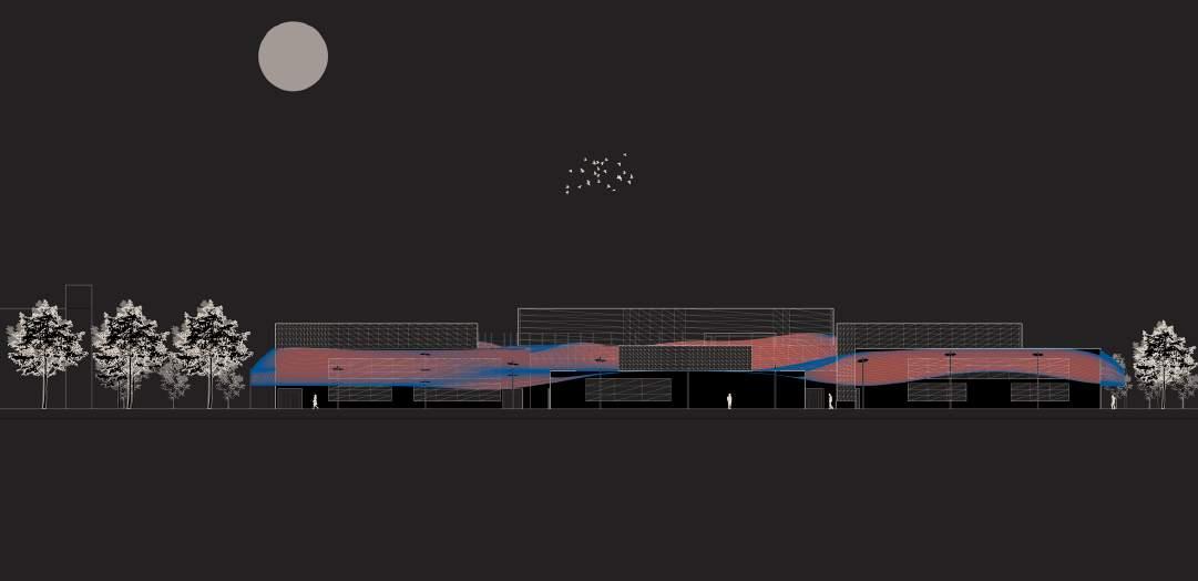
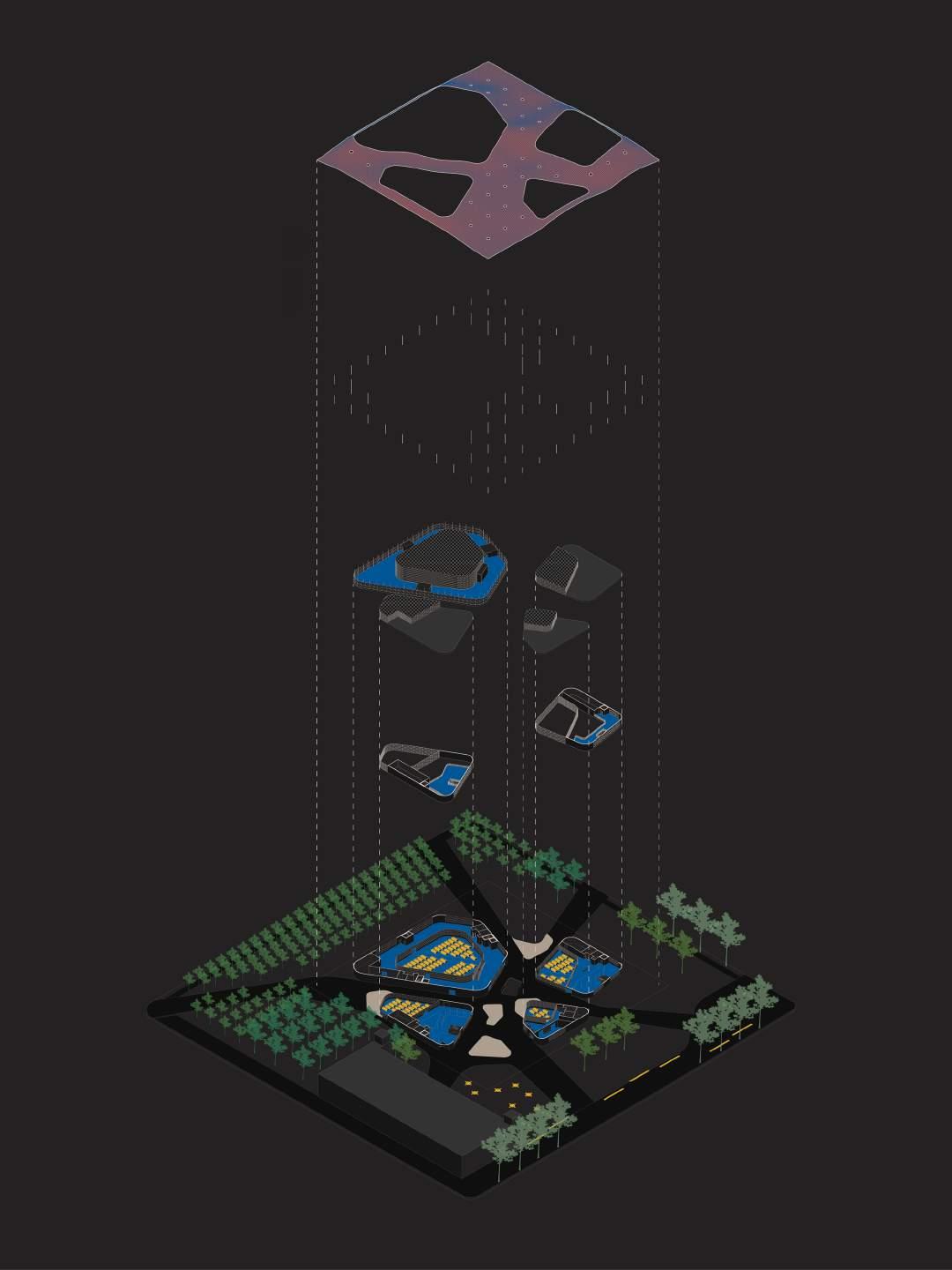
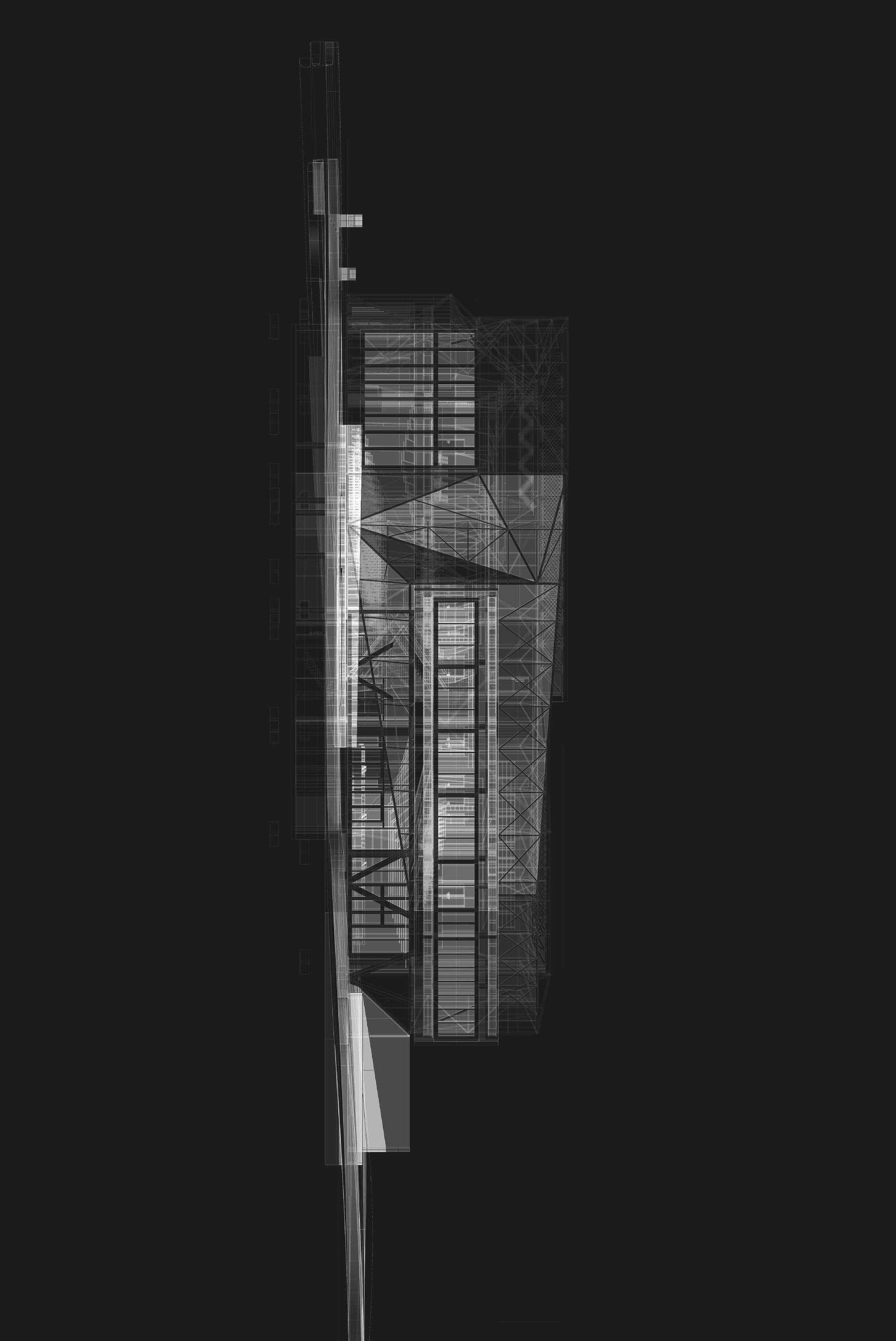
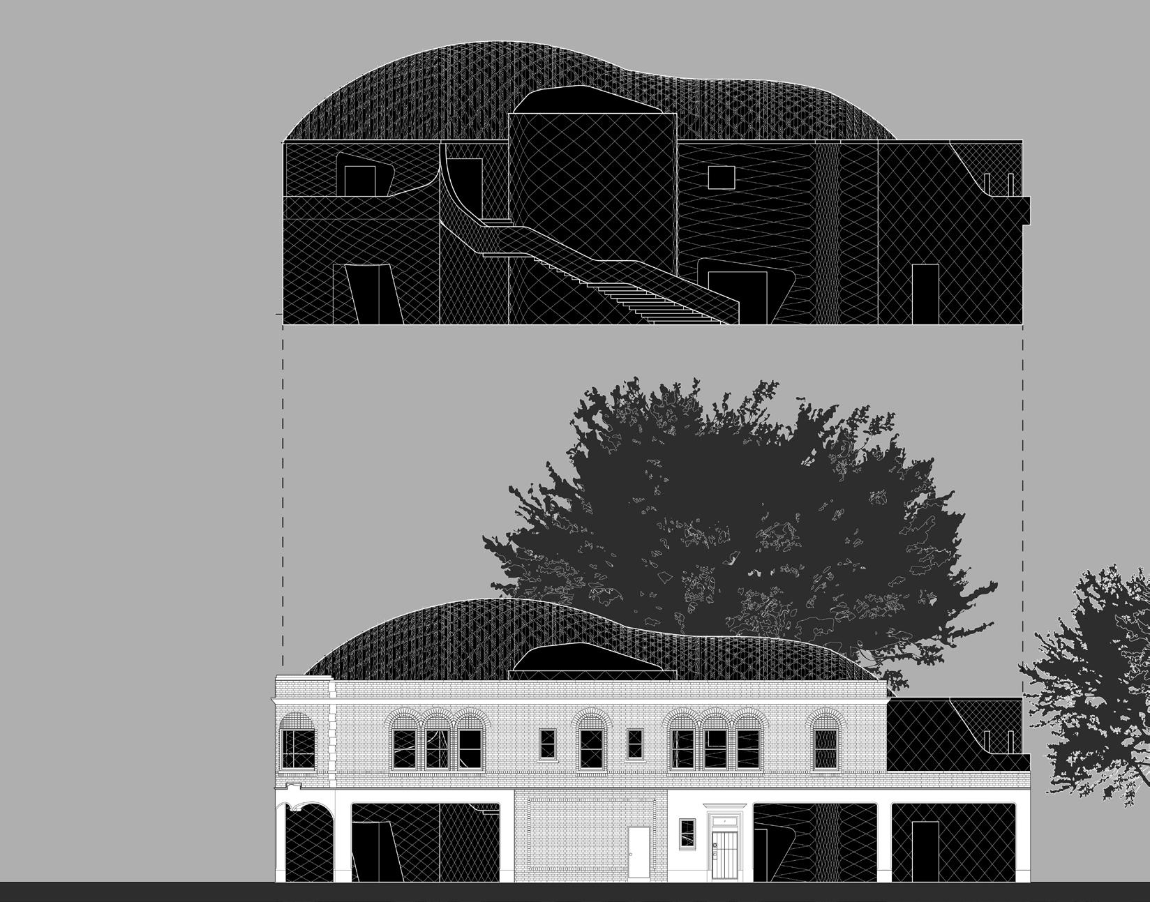
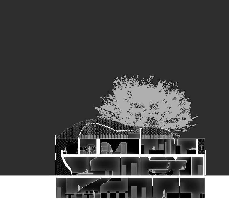
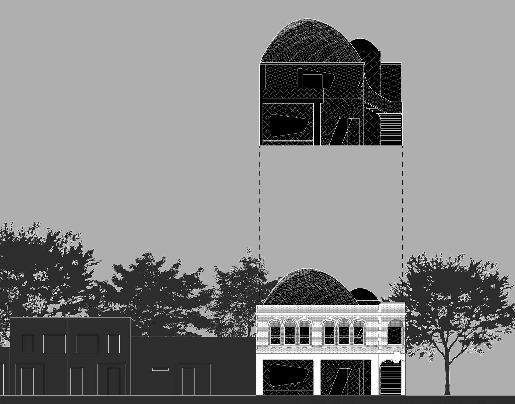
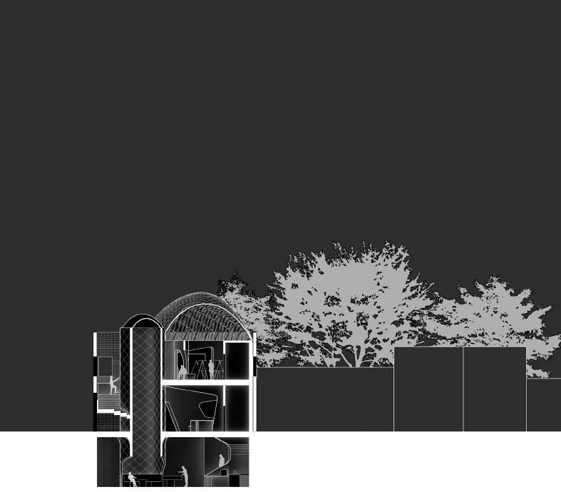
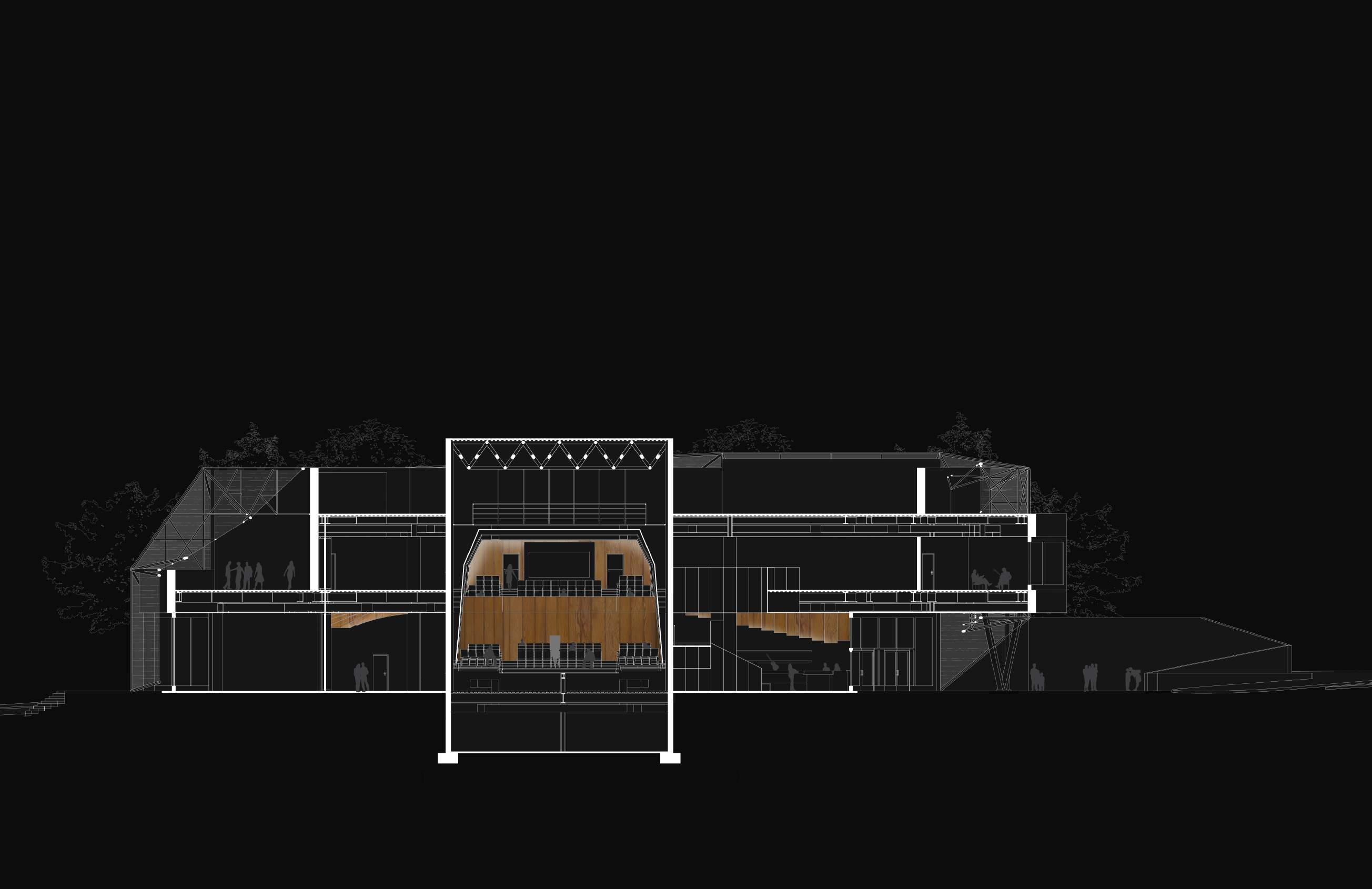
X-Ray of South Elevation
(Image produced using a combination of Rhino 3D, Photoshop, and Illustrator.)

A key notion during the concept phase was how each street along the site could essentially act as a spectator for music in an audible and educational manner.
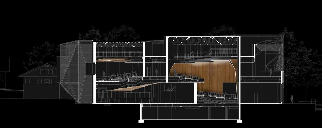
1. Three performance spaces are established. Each is oriented to its own side and has a different scale.
2. The three performance spaces are encased within one volume but remain seperate.
4. Conteracting the obscurity, the facade is lifted and punctured to provide visibility into the building while highlighting the activity occuring inside.
3. A seemingly weightless facade acts as a veil for the imposing structure. It encloses sound and program within its boundaries. The interior activity becomes obscured to the pubilic.
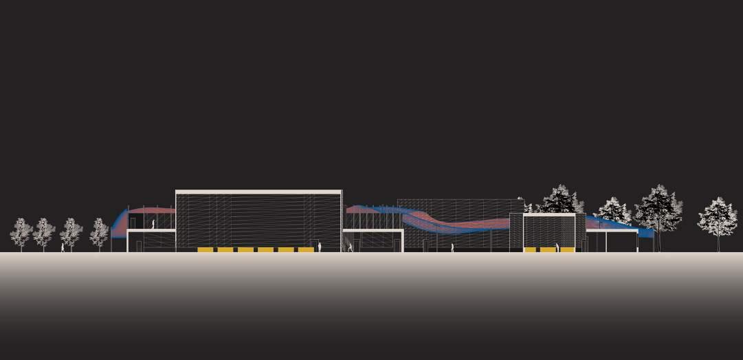
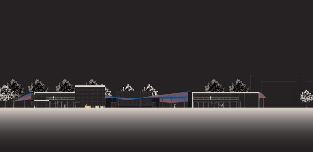
5. The exterior becomes an extension of the interior program, provide spaces for an outdoor performance and an out door market.
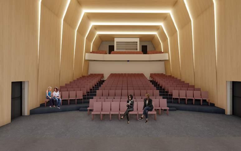
This experience of music is guided by the impacts that concavity and convexity have on acoustics. Wood paneling is arranged in convex shapes within performance halls so performers can gauge the quaility of their music. In other spaces, wood paneling is used in a concave manner to emphasize activity.
Concavity and convexity reflect sound differently. This affect on acoustics is translated to spatial and visual applications both on the interior and exterior.
FACADE STRUCTURE
FACADE STRUCTURE
FACADE STRUCTURE
FLOOR SLAB
ROOF TOP OF PERFORMANCE
COLUMNS AND BEAMS
FACADE STRUCTURE
SPACE FRAMES
FACADE STRUCTURE
FACADE STRUCTURE
FACADE STRUCTURE
FLOOR SLAB
FACADE STRUCTURE
ROOF TOP OF PERFORMANCE
ROOF TOP OF PERFORMANCE
ROOF TOP OF PERFORMANCE
SPACE FRAMES
SPACE FRAMES
FLOOR SLAB
FLOOR SLAB
COLUMNS AND BEAMS
FLOOR SLAB
FLOOR SLAB
COLUMNS AND BEAMS
FLOOR SLAB
ROOF TOP OF PERFORMANCE
FACADE STRUCTURE
ROOF TOP OF PERFORMANCE
FACADE STRUCTURE
FACADE STRUCTURE
ROOF TOP OF PERFORMANCE
ROOF TOP OF PERFORMANCE
SPACE FRAMES
ROOF TOP OF PERFORMANCE
SPACE FRAMES
COLUMNS AND BEAMS
COLUMNS AND BEAMS
ROOF TOP OF PERFORMANCE
ROOF TOP OF PERFORMANCE
SPACE FRAMES
SPACE FRAMES
SPACE FRAMES
FLOOR SLAB
SPACE FRAMES
FLOOR SLAB
SPACE FRAMES
FLOOR SLAB
SPACE FRAMES
FLOOR SLAB
FLOOR SLAB
FLOOR SLAB
FLOOR SLAB
COLUMNS AND BEAMS
FLOOR SLAB
COLUMNS AND BEAMS
FLOOR SLAB
COLUMNS AND BEAMS
COLUMNS AND BEAMS
FLOOR SLAB
COLUMNS AND BEAMS
COLUMNS AND BEAMS
COLUMNS AND BEAMS
COLUMNS AND BEAMS
FLOOR SLAB
COLUMNS AND BEAMS
COLUMNS AND BEAMS
FLOOR SLAB
COLUMNS AND BEAMS
FLOOR SLAB
FLOOR SLAB
FLOOR SLAB
FLOOR SLAB
FLOOR SLAB
FLOOR SLAB
FLOOR SLAB
COLUMNS AND BEAMS
FLOOR SLAB
COLUMNS AND BEAMS
4” Concrete Slab
3” Concrete Slab
COLUMNS AND BEAMS
COLUMNS AND BEAMS
COLUMNS AND BEAMS
COLUMNS AND BEAMS
COLUMNS AND BEAMS
2” Depth Steel Corrugated Decking
1.75’ x 1.75’ HVAC Duct
FLOOR SLAB
FLOOR SLAB
COLUMNS AND BEAMS
COLUMNS AND BEAMS
FLOOR SLAB
COLUMNS AND BEAMS
COLUMNS AND BEAMS
FLOOR SLAB
FLOOR SLAB
FLOOR SLAB
FLOOR SLAB
FLOOR SLAB
COLUMNS AND BEAMS
FLOOR SLAB
FLOOR SLAB
COLUMNS AND BEAMS
FLOOR SLAB
COLUMNS AND BEAMS
COLUMNS AND BEAMS
COLUMNS AND BEAMS
FLOOR SLAB
COLUMNS AND BEAMS
COLUMNS AND BEAMS
COLUMNS AND BEAMS
24” Depth Steel Joist Drainage
Performance Hall Detail
FLOOR SLAB
FLOOR SLAB
FLOOR SLAB
COLUMNS AND BEAMS
FLOOR SLAB
FLOOR SLAB
FLOOR SLAB
FLOOR SLAB
FLOOR SLAB
FLOOR SLAB
MATERIAL CONNECTIONS
Structural
Team: HunTel Engineering Team
Program: Civil Planning
Location: Midwest
Year: Winter 2023 (Completed)
As day to day life sees a continous need for up-to-date communication and connection services, rural areas of the United States look to become current. The team at HunTel Enginneering has dedicated years designing a solution for this goal.
My role in this large scale civil planning project came at the end by analyzing as-built maps for accuracy and translating the information contained in these documents into cloud-based maps. This meant taking physical maps and drafting all contents into an AutoCad file then inputting the same data into a cloud-based catalouge known as “StellaRad.”
In order to check for accuracy, I double-checked the contents of the maps by calculating every individual component and cross referencing with a databook and billing spreadsheet.
As-Built Town Overview (Plan produced using a combination of AutoCad and StellaRad.)
Town Map: All houses and buidlings contain data that has been input into StellaRad and accounted for in a spreadsheet and databook verified by me.
Team: Jesus Perez-Cortez, Sahr Qureishi, Madeline McGill
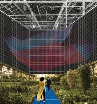
Program: Greenhouse, Mediateque, Incubator, Kitchen, Dining
Location: Omaha, NE
Year: Fall 2020
Course: Dsgn 410 - Collaborate - Salvador Lindquist
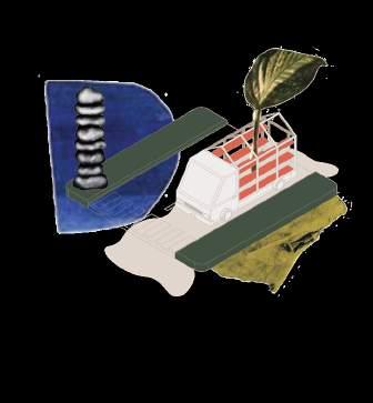
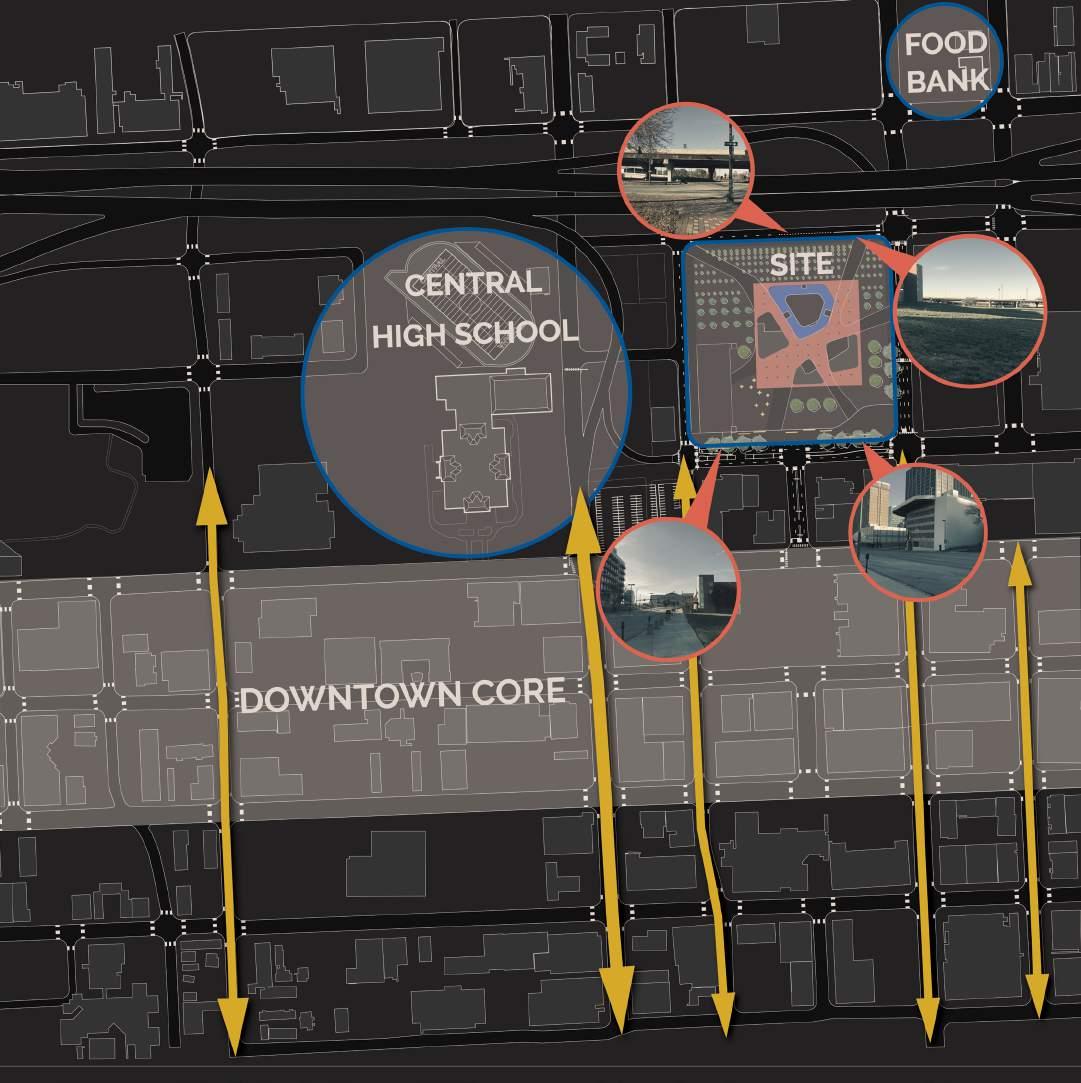
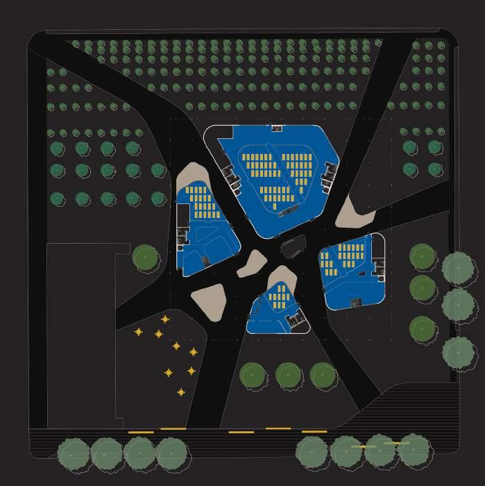
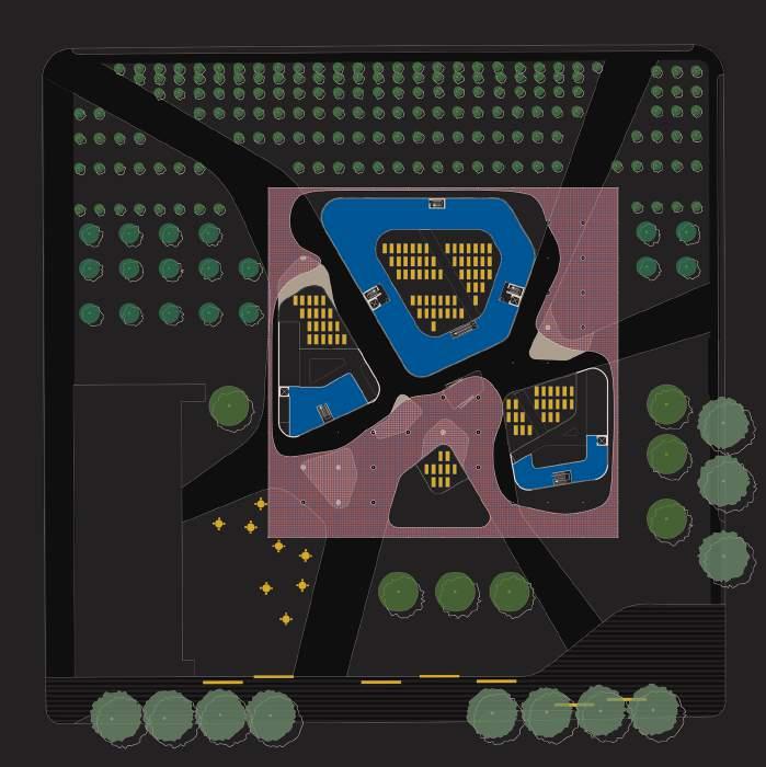
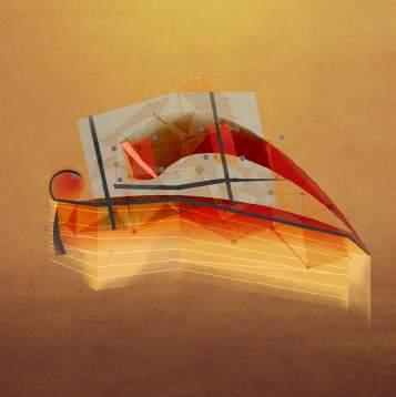
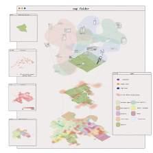
Interpose is a discovery of the inter and disconnected experiences found revolving around food insecurity within and around the realm of secondary education. It is an exploration of students and their daily itineraries and experiences. It is a conscious effort to bring hidden truths to visibility while highlighting a network of converging and diverging human experiences. It is a break from the rigidity of the school system and structure to articulate the notion of a network components and thresholds. The network and threshold are never fully stagnant but are in a state of being, where being is nothing more than the process of becoming.
Interpose is fluid to external parameters and users. The design provides a site with spaces, amenities, and fleets focusing on the pervasive issue of food insecurity allowing students access to healthy foods, social engagement, build cooking skills, transportation, awareness, and knowledge
Millieu Network Map (Image produced using Rhino 3D, Illustrator, and ArcGIS.)
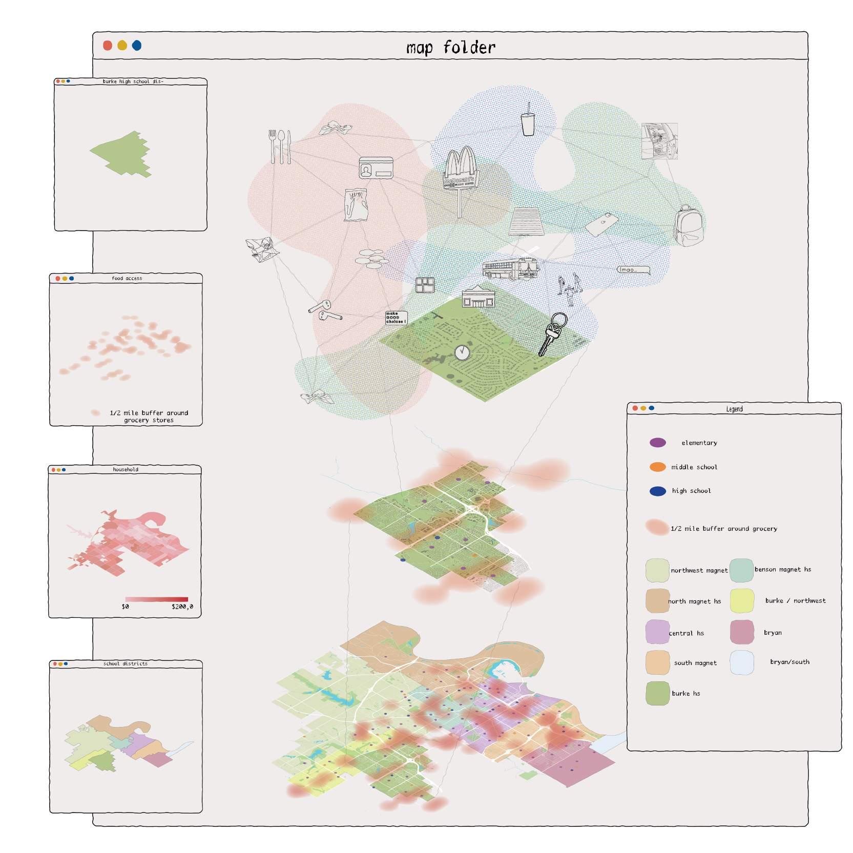
Threshold: A threshold separates opportunity and understanding. It must be acknowledged to be broken.

Exhibition: Raises awareness to people who do not experience or are not aware of food insecurity.
Invitation: Breaks the threshold from those who experience food insecurity and those who do not.

Cultivation: Physically addresses food insecurity through greenhouses, gardens, kitchens, and food trucks.
Convergence: People and experiences meet and dynamically engage with one another on the site.
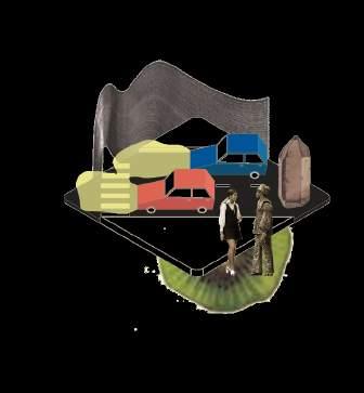
Cars: Mobile Exhibition
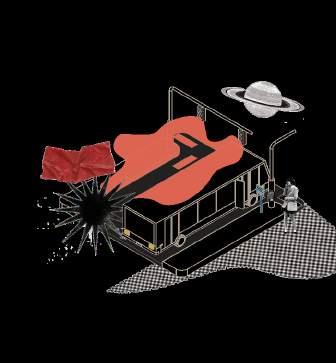
Semi-truck: Mobile Exhibition
The network converges on the site and diverges across the city through a series of programmatic fleets which serve as nodes of exhibition, invitation, and cultivation. There is a disparity of opportunity and understanding created by a threshold of those who experience food insecurity and those who do not.
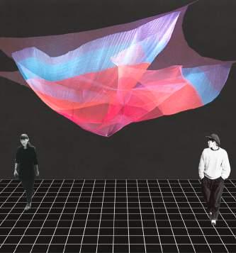
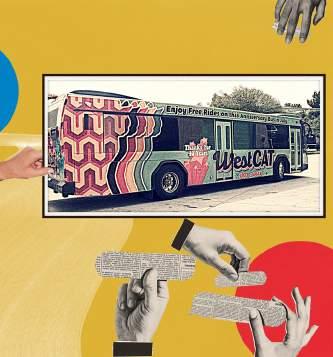
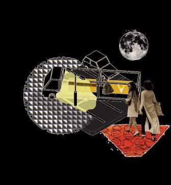
Top Row: Vignettes
Bottom Row: Fleets
Bus: Invitation
Food Truck: Incubator Cultivation
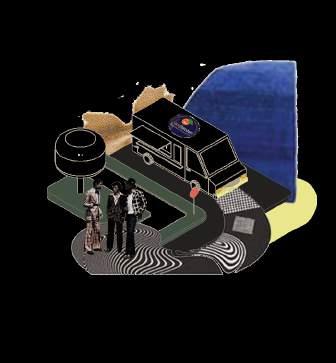
The fleet are pollinators of the network. Blending into the vehicular landscape but also intruding on settings and situations in a way that draws attention to itself and its agencies. The fleets are divided into 5 categories, all serving a different purpose within the network. The categories vary in scale and in intervention.
U-Haul Truck: Resource Cultivation