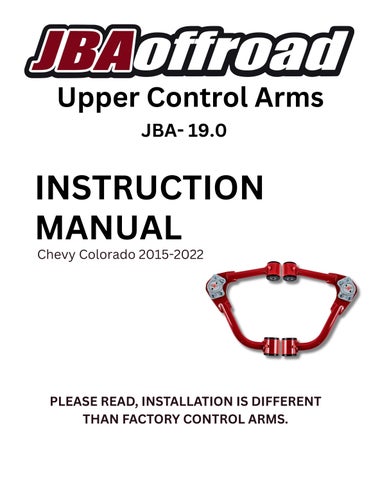
JBA-19.0 Chevy Colorado

Page 1

JBA- 19.0 Upper Control Arm Installation & Maintenance

Chevy Colorado 2015-2022 PLEASE READ, INSTALLATION IS DIFFERENT THAN FACTORY ARMS.


What will void your JBA WARRANTY •Adding ball joint spacers to the JBA upper control arms. •Adding bump stops that hit the JBA upper control arms. •Adding limiting straps attached to the JBA upper control arms. •Cutting, grinding, welding, or modifying the JBA upper control arms. •Using the JBA arms on a vehicle, and/or a lift kit they were not designed for. •JBA upper control arms are not designed to be used when stacking two lift kits together. NO EXCEPTIONS


Index A-Arm Removal............................................................................................1 A-Arm Installation................................................................2-3 Maintenance Procedure........................................................4 Bushing Replacement............................................................5-6 EZ Lube Bushing....................................................................7 JBA Ball Joint..........................................................................8 Front End Alignment............................................................9 Installation Notes..................................................................10 Merchandise...........................................................................11


We take pride in our work at JBA Offroad, but we are human and sometimes make mistakes. Please check our work and ensure we shipped the part number you ordered and that they are a matching set. If there is a mistake on our part, we will correct it as soon as possible. However, if you disassemble your vehicle before you check the parts you received with your order, JBA Offroad is not responsible for any inconvenience this may cause you. Our responsibility is to make sure you received the parts you ordered. Product Number, High Caster Passenger Side for USA vehicles.

No bump stops can contact the JBA upper control arms, or it voids our warranty!


Upper Control Arm Removal 1. Prior to installation, verify your part number ordered with the part number received, Driver Side and Passenger Side stamped in the arm by the ball joint. 2. Jack up vehicle and place a jack stand under the frame rail behind the front wheel. Remove wheel. 3. Remove 2 caliber mounting bolts. Hang caliber out of the way. 4. Remove nut from sway bar end link. 5. Then remove the tie rod end nut. With a hammer, strike the steering knuckle to release the tie rod. 6. Remove nut from ball joint stud. Separate the ball joint from the steering knuckle. Strike the steering knuckle with a hammer to release the grip of the ball joint tapered seat in the steering knuckle. 7. Remove lower and upper mounting bolts and nuts from shock tower. 8. Remove shock assembly. 9. Unbolt the control arm from the frame pockets and remove the upper control arm from the vehicle. Removal Video:

1


Upper Control Arm Installation 1. Grease the outer surface of the Ez Lube Bushings. 2. Hold UCA in place with 0.076" washers closest to the shock tower. Insert the mounting bolts from the outside of shock tower. Add Loctite to the UCA mounting bolts. Torque to 122ft-lbs (Factory specs)

Shock Tower

3. Reinstall shock assembly, torque lower mounting bolt to 66 ft-lbs (Factory specs) and torque upper mounting nuts to 50ft-lbs (Factory specs). 4. Put ball joint stud through the spindle. Install nut using a 3/8 open end wrench on the stud to keep it from spinning, then use a torque wrench and Torque nut to 60ft-lbs. 5. Connect the tie rod and torque the nut to 76ft-lbs (Factory Specs) 6. Reconnect the sway bar link, torque to 55ft-lbs (Factory specs) 7. Reconnect the caliber. 8. Check torque of ball joint bolts. (Torque to 13ft-lbs.)

2


Upper Control Arm Installation

9. Grease the ball joint with 3-4 pumps of lithium complex grease fortified with moly (molybdenum disulfide), until boot begins to swell. Grease the bushings with lithium complex grease fortified with moly (molybdenum disulfide) until you see grease pushing out from the bushing’s EZ lube ports. 10.

Mount the wheel and torque the lug nuts in a star pattern.

11.

Repeat on the other side.

12.

Lower vehicle off of jack stand.

Install Video:

3


Maintenance Procedure

Every 3,000-5,000 miles: (at the interval of every oil change) -Grease the ball joint with 3-4 pumps of lithium complex grease fortified with moly (molybdenum disulfide). -Grease the upper control arms with lithium complex grease fortified with moly (molybdenum disulfide), until you see grease consistently pushing out from the bushing’s EZ lube ports. -Perform a visual inspection of the ball joint boots. Ensure there are no large tears or damage to the rubber. If you see significant damage, we recommend replacing the boot with a new one. Replacement boots can be purchased through our website at: https://jbaoffroad.com/ball-joint-boots.html

4

Ball Joint Replacement Video:


Bushing Replacement Replacement instructions for bushing kit #JBA-TC-69000EZ-19.0 1. Press in the inner bushings first.

2. Open the grease packet, squeeze grease in the surface of the ¾” hole of all 8 bushings. 3. Put a thin coat of grease on the steel sleeves. 4. Squeeze the excess grease from the tube in on the center of the bong filling the gap between the black bushings with grease. 5. Press in the outside bushings.

6. Press in the steel sleeves.

5


Bushing Replacement 7. With the excess grease that squeezes out, apply it to the outsides of the bushings 8. Hold UCA in place and insert long shear bolt from the front of the vehicle towards the back.

The proper orientation: Shear bolt head, washer, black bushing, red bushing housing, black bushing, 0.076” washer, UCA tube mounted to the chassis, other side 0.076” washer, black bushing, red bushing sleeve, black bushing, and nut.

Shock Tower

6


JBA EZ Lube Bushings

JBA has a patent on our control arm bushings. The EZ lube bushings have grease ports with a check valve. There is no need to loosen the mounting bolts to release the grease pressure. The maintenance procedure is simple: Attach grease gun to the bushing valve, pump lithium complex grease fortified with moly (molybdenum disulfide) until you see grease pushing out from the bushing face. It builds up pressure and flows all around the ports in the bushing. Attach grease gun to the ball joint grease fitting, add 3-4 pumps of lithium complex grease fortified with moly (molybdenum disulfide). 1 grease cartridge will be more than sufficient.

7


JBA Ball Joint

We recommend using Mobilgrease XHP™ 222 Special lithium complex grease or lithium complex grease fortified with moly (molybdenum disulfide), it is intended for a wide variety of applications and severe operating conditions. These greases were designed to outperform conventional products by applying cutting edge, proprietary, lithium complex manufacturing technology. It is formulated to provide excellent high temperature performance with superb adhesion, structural stability, and resistance to water contamination. This grease has a high level of chemical stability and offer excellent protection against rust and corrosion. This grease feature high dropping points and maximum recommended operating temperature of 140º C (284°F). Mobilgrease XHP 222 Special grease available in NLGI grades 2 or 3 with an ISO VG 220 base oil viscosity. Mobilgrease XHP 222 Special grease is designed for a wide range of applications including the industrial, automotive, construction and marine sectors. Their performance features make them ideal choices for operating conditions including high temperature, water contamination, shock loading and extended re-lubrication operations. Mobilgrease XHP 222 Special is an extreme pressure grease fortified with 0.75% molybdenum disulfide that provides protection from wear under conditions pivoting and other conditions that lead to loss of oil film.

8


Front End Alignment

0.2

0.1

2.8

2.7

0.07

0.05

Factory alignment specs for basically all vehicles call for a certain degree of positive caster. This ensures good stability, helps maintain straight-ahead direction and promotes steering wheel self-centering. Camber is the inward or outward tilt of the front tires as viewed from the front. Toe-in is the amount the tires point in at each other from being parallel with each other. The higher you lift an IFS vehicle the less caster you will have, the JBA upper control arms will help replace the caster lost from lifting your vehicle.

9


Installation Notes Installation Date _________ Mileage on vehicle ____________ Lift Kit Installation Notes: Measure center of wheel to underside of fender flare. List ride height Before and After: Driver Side Front B____________ A____________

Passenger Side Front B____________ A____________

Driver Side Back B____________ A____________

Passenger Side Back B____________ A____________

Maintenance schedule grease every 3 Months or 3,000 to 5,000 Miles. Mileage____________

Date__________

Mileage____________

Date__________

Mileage____________

Date__________

Mileage____________

Date__________

Mileage____________

Date__________

Mileage____________

Date__________

Mileage____________

Date__________

Mileage____________

Date__________

Mileage____________

Date__________

Save your front end alignment sheet from your Tech with these notes.

10


Merchandise

11


855.533.7437 704 Forman Rd. Souderton, PA 18964 sales@JBAoffroad.com


Turn static files into dynamic content formats.

Create a flipbook
Issuu converts static files into: digital portfolios, online yearbooks, online catalogs, digital photo albums and more. Sign up and create your flipbook.