
ARRAY FACTOR IN CURVED MICROSTRIPLINE ARRAY ANTENNA FOR RADAR COMMUNICATION SYSTEMS
Putu Artawan
Yono Hadi Pramono
Mashuri
and Josaphat T. Sri Sumantyo3
1Physics Department, Faculty of Mathematics and Natural Sciences, Ganesha University of Education (Undiksha), Singaraja, Bali, Indonesia
2Physics Department, Faculty of Natural Sciences, Institut Teknologi Sepuluh Nopember (ITS), Surabaya, Indonesia
3Josaphat Microwave Remote Sensing Laboratory, Center for Environmental Remote Sensing (CEReS) Chiba University, 1 33 Yayoi cho, Inage ku, Chiba 263 8522 Japan
ABSTRACT
This paper presents the designed of varians array in curved microstripline antenna for radar communication. The antenna geometry comprises of three varians in matrics 2x2, 2x4 and 4x4 dimensions. The several array operates in C Band frequencies (4GHz 8GHz) and X Band frequencies (8GHz 12GHz) with a 1.82 VSWR, 18.72dB Return loss, 0.29 reflection coefficient, and 5.8dB gain for 2x2 array, 1.64 VSWR, 16.17dB Return loss, 0.24 reflection coefficient, and 5.4dB gain for 2x4 array, 1.04 VSWR, 37.70dB Return loss, 0.19 reflection coefficient, and 7.6dB gain for 4x4 array. All of the varians in array elements are feed using a direct feeding technique. This array antenna is suitable developed for use in radar communication systems.
KEYWORDS
Array, Curved microstripline, Radar communication, C Band, X Band
1. INTRODUCTION
Researches on Design of Antenna had conducted previously. The variation of design, the analysis, and the result obtained were not be optimal to be conducted in its application especially in radar communication systems. In this research, 2x2, 2x4, and 4x4 varian arrays in curved microstripline antenna was designed. In radar communications, there is a emphasizing need to minimize the size, weight and power requirments of antenna in array varians. The concept of array antennas with widely separated frequencies bands. Thus, in this research multiband frequencies antenna elements have been designed and fabricated that can potentially to develope radar communication systems. A novel design in microstrip antenna is one type of antenna that is designed using a PCB (Printed Circuit Board). Microstrip antennas are physically components that are designed to emit and or receive electromagnetic waves. In this antenna design also considerated the size of feeding stripline to reach the maximum results in antenna indicator parametric. As a goal of this research is to find the optimum indicator parametric results in S11, Voltage Standing Wave Ratio (VSWR), Return Loss, Reflection Coefficient and gain that can be develope in radar application communications.
THEORIES
Microstrip Antenna
Factor
low cost, easily fabricated
at various frequencies [1]. There
There is a rectangular,
design. The design of the
study designed novel curved
greater
so that it could be
also have


(b)
(c)
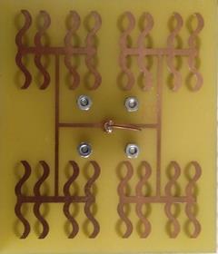
Figure 4. Curved microstripline array varians antenna prototype. (a). 2x2 Array Varians. (b) 2x4 Array Varians. (c) 4x4 Array Varians.


Curved microstripline array varians antenna prototype was fabricated by UV photoresist laminate. In our work, the antenna prototypes are fabricated on Flame Retardant 4 (FR4) material with 4.3 dielectric constant. The first step in the fabrication process is to generate the photo mask artwork by printing on stabline or rubylith negative film of the desired geometry on butter sheet. Using the precision cutting blade of a manually operated co ordino graph the opaque layer of the stabiline or rubylith film is cut to the proper geometry and can be removed to produce either a positive or negative film representation of the antenna sketches. The design dimensions and tolerances are verified on a cordax measuring instrument using optical scanning. Enlarged artwork should be photo reduced using a high precession camera to produce high resolution negative, which is later used for exposing the photo resist. The photographic negative must be now held in very close contact with the polyethylene cover sheet of the applied photo resist using a vacuum frame copy board or other technique, to assure the fine line resolution required. With exposure to proper wavelength of light, polymerization of the exposed photo resist occurs making it insoluble in the developer solution. Now, it is then coated with a negative photo resist and exposed to UV radiation and it is immersed in developer solution up to two minutes through the mask. The exposed photo resist hardens and those in the unexposed areas are washed off using a developer. The unwanted copper portions are now removed using Ferric Chloride (FeCl3) solution. FeCl3 dissolves the copper coating on the laminate except which is underneath the
International Journal of Antennas (JANT) Vol.7, No.1, January 2021
hardened photo resist layer after few minutes. Finally, the laminate is then washed with water and cleaned in acetone solution to remove the hardened negative photo resist. The fabrication process has shown in the following figure.


Figure 5. Fabrication Process.


The curved microstripline array varians antenna shown in Figure 6 has been modeled in CST programme to determine S11 parameter, Voltage Standing Wave Ratio (VSWR), Return Loss, Reflection Coefficient and Radiation Pattern.


International Journal of Antennas (JANT) Vol.7, No.1, January 2021
(a) S11 Parameter. (b) VSWR. (c) Radiation Pattern.


Figure 6. Curved microstripline 2x2 array varians antenna simulations. (a) S11 Parameter Simulation. (b) VSWR Simulation. (c) Radiation Pattern Simulation.

International Journal of Antennas (JANT) Vol.7, No.1, January 2021
(a) S11 Parameter. (b) VSWR. (c) Radiation Pattern.


Figure 7. Curved microstripline 2x4 array varians antenna simulations. (a) S11 Parameter Simulation. (b) VSWR Simulation. (c) Radiation Pattern Simulation.

International Journal of Antennas (JANT) Vol.7, No.1, January 2021
(a) S11 Parameter. (b) VSWR. (c) Radiation Pattern.


Figure 8. Curved microstripline 4x4 array varians antenna simulations. (a) S11 Parameter Simulation. (b) VSWR Simulation. (c) Radiation Pattern Simulation.
Antenna measurement using a Network Analyzer type device the Agilent 8510 Vector Network Analyzer. With result: (a)
International Journal of Antennas (JANT) Vol.7, No.1, January 2021
(b) (c)
(a) S11 Parameter. (b) VSWR. (c) Radiation Pattern.


Figure 9. Curved microstripline 2x2 array varians antenna measurements. (a) S11 Parameter Measurement. (b) VSWR Measurement. (c) Radiation Pattern Measurement. (a) (b)

International Journal of Antennas (JANT) Vol.7, No.1, January 2021
(c)
(a) S11 Parameter. (b) VSWR. (c) Radiation Pattern.


Figure 10. Curved microstripline 2x4 array varians antenna measurements. (a) S11 Parameter Measurement. (b) VSWR Measurement. (c) Radiation Pattern Measurement. (a) (b)

International Journal of Antennas (JANT) Vol.7, No.1, January 2021
(c)
(a) S11 Parameter. (b) VSWR. (c) Radiation Pattern.

Figure 11. Curved microstripline 4x4 array varians antenna measurements. (a) S11 Parameter Measurement. (b) VSWR Measurement. (c) Radiation Pattern Measurement.
In general, base on the simulation and the measurement results, curved microstripline array varians antenna has the optimal parametric characteristic as a good requirements antenna that can be develop in radar communication applications. The characteristics of Curved microstripline array varians antenna can be described in the following table.
Table 1. Curved microstripline array varians antenna characteristics.
Indicator Value Standard Parametric VSWR
Array 2 x 2 1.82 Array 2 x 4
1 < VSWR < 2 1.64 Array 4 x4 1.04
Return Loss Array 2 x 2 18.72 Array 2 x 4
< 10 dB 16.17 Array 4 x4 37.70
Reflection Coefficient Array 2 x 2 0.29 Array 2 x 4
Close to 0 0.24 Array 4 x4 0.19
Gain Array 2 x 2 5.8 Array 2 x 4
> 4dB 5.4 Array 4 x 4 7.6
International Journal of Antennas (JANT) Vol.7, No.1, January 2021
4. CONCLUSION
Adding Arrays to the Curved Microstripline Antenna gives more optimal results especially in the range of working frequencies (bandwidth) and also the resulting gain. The results indicate that the antenna is able to apply in multiband frequency. The radiation pattern produced in this design is Omnidirectional in linear polarization. The band frequencies array in this design is capable to develope in radar application communication systems.
ACKNOWLEDGMENT
The authors would like to thank the Indonesian Ministry of Research, Technology and Higher Education through LPDP and PKPI (Sandwich like) scholarships, Center for Environmental Remote Sensing (CEReS), Josaphat Tetuko Sri Sumantyo (JMRSL Chiba University), Promotor Yono Hadi Pramono and Mashuri (Physics Department, ITS Surabaya), and Ganesha University of Education (Undiksha), Singaraja Bali.
REFERENCES
[1] Artawan. Fabrikasi dan Karakterisasi Antena Mikrostrip Tapered Patch Untuk Aplikasi Antena Panel Pada Frekuensi 2,4GHz. Tesis Magister, Jurusan Fisika, Fakultas Matematika dan Ilmu Pengetahuan Alam, Institut Teknologi Sepuluh Nopember (ITS), Surabaya, 2011.
[2] Artawan, Hadi Pramono, Yono. Perancangan Antena Panel Mikrostrip Horn Array 2x2 Untuk Komunikasi Wi Fi Pada Frekuensi 2,4GHz. Prosiding Simposium Fisika Nasional (SFN), ITS, Surabaya, 2010.
[3] Balanis, C.A. Antena Theory Analysis and Design. Second Edition, John Wiley and Sons, New York, 1997.
[4] Edward, Terry. Foundation For Microstrip Circuit Design. Knaresborough England, 1991.
[5] Shafai. Microstrip Antena Design Handbook. Profesor University Of Manitoba, Wimmipeg, Canada, 2001.
[6] Kraus, John, D. Electromagnetics. Third Edition, McGraw Hill, New York, 1984.
[7] Ohri, V, Amin, O, Gebremariam, H Dubois, B. Microwave Mikrostrip Horn Antena Design and Test System. San Jose State University, 2003.
[8] Masduki, K. Desain, Fabrikasi dan Karakterisasi Antena Mikrostrip Biquad dengan CPW (Coplanar Waveguide) pada Frekuensi Kerja 2,4GHz. Program Magister Bidang Keahlian Optoelektronika Jurusan Fisika, FMIPA ITS: Surabaya. 2009.
[9] Hund, E. Microwave Communications, Component and Circuit. McGraw Hill, New York, 1989.
[10] Hadi Pramono, Yono. Karakterisasi Antena Mikrostip Patch 3GHz Secara Simulasi FDTD (Finite Difference Time Domain) Dan Eksperimen. Jurnal Fisika. Institut Teknologi Sepuluh Nopember. Surabaya, 2005.
[11] Hadi Pramono, Yono. Prototipe Antenna Bi Mikrostrip Tapered Patch dengan Dua Arah Pola Radiasi Dan Satu Feeding Monopole Beroperasi Pada Freq.2,4GHz. Prosiding T. Informatika, UPN. Yogyakarta, 2009.
International Journal of Antennas (JANT) Vol.7, No.1, January 2021
[12] Hidayah, Ifa. Desain dan Fabrikasi Antena Bi Mikrostrip Tapered Patch dengan Dua Arah Radiasi dan Satu Feeding Monopole Untuk Komunikasi Wi fi. Tesis Magister. Institut Tekologi Sepuluh Nopember. Surabaya, 2009.
[13] Naqiah, Hawaun. Fabrikasi dan Karakterisasi Antena Mikrostrip Loopline untuk Komunikasi Wireless Local Area Network (WLAN). Program Magister Bidang Keahlian Optoelektronika Jurusan Fisika FMIPA ITS: Surabaya, 2009.
[14] Risfaula, Erna. Antena Mikrostrip Panel Berisi 5 Larik Dipole dengan Feedline Koaksial Waveguide untuk Komunikasi 2,4GHz. Program Keahlian Optoelektronika Jurusan fisika FMIPA ITS: Surabaya, 2011.
[15] S. Gao, Q. Luo, F. Zhu, Circularly Polarized Antenna, John Wiley & Sons, Ltd, 2014.
[16] S. Murugan, V. Rajamani, “Study of Broadband Circularly Polarised Microstrip Antenna” Science Engineering and Management Research (ICSEMR), 2014 International Conference on. IEEE, 2014.
[17] Haider Raad, “An UWB Antenna Array for Flexible IoT Wireless System,” Progress In Electromagnetics Research, Vol. 162, 109 121, 2018.
[18] Kurniawan Farohaji, Sri Sumantyo, J. T, Gao Steven, Ito Koichi, Edi Santosa C. “Square Shaped Feeding Truncated Circularly Polarised Slot Antenna”. IET Microwaves, Antenna & Propagation Journals. ISSN 1751 8725, 2018.
[19] Edi Santosa C, Sri Sumantyo, J.T, Yam Chua Ming, Urata Katia, Ito Koichi, Gao Steven. “Subarray Design for C Band Circularly Polarized Synthetic Aperture Radar Antenna Onboard Airborne,” Progress In Electromagnetics Research, Vol. 163, 107 117, 2018.
[20] Xu Mao Chun, Gao Steven, Wang Yi, Sri Sumantyo, J.T. “Compact Broadband Dual Sense Circularly Polarized Microstrip Antenna/Array With Enhanced Isolation”. IEEE Transactions on Antennas And Propagation, Vol 65, No.12, 2017.
[21] Luo Qi, Gao Steven, Sobhy Mohammed, Sri Sumantyo, J.T, Li Jianzhou, Wei Gao, Xu Jiadong, Wu Changying. “Dual Circularly Polarised Equilateral Triangular Patch Array”. IEEE Transactions on Antennas And Propagation, Vol 64, No.6, 2016.
[22] Kumar Dwivedi M, Srivastava Pragati. “Microstrip Patch Array Antenna for X Band Application”. Antenna Test and Measurement Society (ATMS India 16), 01 03 Feb, 2016.