
OF MICROSTRIP
ABSTRACT
A Microstrip Patch Antenna is a type of radio antenna with a low profile, which can be mounted on a low surface. It is a narrow band, wide-beam fed antenna fabricated by etching the antenna element pattern in metal trace bonded to the dielectric Substrate such as a printed circuit board with a continuous metal layer bonded to the opposite side of the substrate which forms a ground plane. The main aim of this work is to design, develop and test the Printed Circuit antenna (Microstrip Patch antenna) suitable for use in L-band frequency range of 1-2GHz. This study also emphasizes on simulation of micro-strip patch antenna using IE3D software to simulate & study the radiation pattern & other radiation pattern parameters and comparison with specifications/requirements. Co-axial Feed technique was adopted and the location of the feed point was varied within the radiating patch to arrive at the point of minimum return loss. This work is also focused on characterization of fabricated antenna in view of parameters like VSWR, Antenna efficiency, Axial ratio, Gain and radiation pattern
KEYWORDS
1. INTRODUCTION
A rectangular microstrip patch antenna, suitable for use in L-band frequency range of 1-2 GHz was designed and modeled using IE3D software. The simulated antenna was analyzed using coaxial feed technique and various antenna parameters like S11, VSWR, Antenna Gain and Antenna Efficiency were determined for the random feed point location. Also, the feed point was varied within the radiating patch to arrive at the optimized feed location for minimum return loss. Further, a microstrip patch antenna was fabricated using the dimensions of the simulated antenna. The fabricated antenna was tested for obtaining the radiation pattern and other antenna parameters using standard anechoic chamber testing set up at ISAC/ISRO. The antenna parameters were compared between simulation results and experimental results and the antenna was qualified for use in L-band frequency range with minimum return loss and maximum bandwidth.
A microstrip patch antenna consists of a radiating patch on one side of a dielectric substrate and a ground plane on the other side [6].
InternationalJournalofAntennas(JANT)Vol.3,No.1/2/3,July2017 DOI:10.5121/jant.2017.3301 1
EVELOPMENT
PATCH ANTENNA Aishwarya Sudarsan and Apeksha Prabhu Department of Electronics and Communication Engineering, NHCE, Bangalore, India
Microstrip Patch Antenna, VSWR, Radiation Pattern, Co-axial feed
Figure1.BasicStructureofMicrostripPatchAntenna
Due to the fringing effects, the patch of the microstrip antenna looks greater than its physical dimensions as shown in Fig.2. Where the dimensions of the patch along its length have been extended on each end by ∆L.
Figure2.PhysicalandeffectivelengthsofRectangularMicrostrippatchAntenna

The length and width of the patch determines the characteristics of the antenna. The dimensions of a microstrip patch antenna depend on the resonant frequency and value of the dielectric constant.

2. LITERATURE STUDIES
A Micro strip antenna has drawn the attention of researchers over the past work because of their many attractive features. The micro strip patch structures are relatively easy to manufacture and have turned micro strip analysis into an extensive research problem. Research on micro strip antenna in the 21st century aimed at size reduction, increasing gain, wide bandwidth, multiple functionality and system-level integration. [2-3]. With the wide spread proliferation of wireless communication technology in recent years, the demand for compact, low profile and broadband antennas has increased significantly. To meet the requirement, the micro strip patch antenna have been proposed because of its low profile, light weight and low cost.[1] Micro strip Patch Antenna consists of a conducting rectangular patch of width "W" and length "L" on one side of dielectric substrate of thickness "h" and dielectric constant "εr". Common micro strip antenna shapes are square, rectangular, circular and elliptical, but any continuous shape is possible.
There are several techniques available to feed or transmit Electromagnetic energy to a micro strip patch antenna. The role of feeding is very important in case of efficient operation of antenna to
InternationalJournalofAntennas(JANT)Vol.3,No.1/2/3,July2017 2
improve the antenna input impedance matching. The feeding techniques used in the micro strip antenna are divided into two important classes as given below:-
Contacting Feed: - In this method, the patch is directly fed with RF power using the contacting element such as micro strip line or coaxial line. The most commonly used contacting fed methods are Micro strip Feed and Co-Axial Feed.
Non-Contacting Feed: - In this method, the patch is not directly fed with the RF power but instead power is transferred to the path from the feed line through electromagnetic coupling. The most commonly used non- contacting feed methods are Aperture Coupled feed and Proximity Coupled Feed.
The role of feeding is very important in case of efficient Operation of antenna to improve the antenna input Impedance matching. [7] The various types of feeding Techniques are:-
1. Microstrip Line Feed
2. Inset Feed
3. Co-axial Feed
4. Aperture Coupled Feed
5. Proximity Coupled Feed
A. Microstrip line Feed:-
In this type of feed technique, a conducting strip is connected directly to the edge of the Microstrip patch. The conducting strip is smaller in width as compared to the patch and this kind of feed arrangement has the advantage that the feed can be etched on the same substrate to provide a planar structure. [8]
B. Inset Feed
In is a type of microstrip line feeding technique, in which the width of conducting strip is small as compared to the patch and has the advantage that the feed can provide a planar structure. [2] The purpose of the inset cut in the patch is to match the impedance of the feed line to the patch input impedance without the need for any additional matching element. This can be achieved by properly adjusting the inset cut position and dimensions. [6]
C. Co-axial Feed technique
The coaxial probe feeding is a very common technique used for feeding Micro strip patch antennas. The inner Conductor of the coaxial cable extends through the dielectric and is soldered to the radiating metal patch, while the outer conductor is connected to the ground plane. The advantage of this feeding scheme is that the feed can be placed at any desired location on the patch in order to match cable impedance with the antenna input impedance.[4]The main aim to use probe feeding is it enhances the gain, provides narrow bandwidth and impedance matching. [5]
InternationalJournalofAntennas(JANT)Vol.3,No.1/2/3,July2017 3
D. Aperture coupled Feed
In this type of feed technique, the radiating patch and the microstrip feed line are separated by the ground plane. Coupling between the patch and the feed line is made through a slot or an aperture in the ground plane.
E. Proximity coupled Feed
This type of feed technique is also called as the electromagnetic coupling scheme. Two dielectric substrates are used such that the feed line is between the two substrates and the radiating patch is on top of the upper substrate. The main advantage of this feed technique is that it eliminates spurious feed radiation and provides very high bandwidth (as high as 13), due to overall increase in the thickness of the microstrip patch antenna.
3. ANTENNA DESIGN EQUATIONS
The initial microstrip patch antenna design parameters, Patch length L, Patch Width W, feed location (X,Y), from the centre of the patch, ground plane length and ground plane width were estimated using the following design equations with frequency fo=1.176GHz, Ɛr=2.33 and h=1.6mm.
3.1 Width of Antenna (W)
Where the light speed ‘c’ is taken as 3x10⁸ m/s. On Substitution, the width (W) of the antenna was calculated as 98.8mm.
3.2 Length of Antenna (L)
The effective dielectric constant is given by:
Where, h - height of the substrate W - Width of the antenna ɛr - Relative Permittivity
On substitution, the effective dielectric constant (Ɛreff) was calculated to be 2.273.
The extended length of the patch (∆L) is given by,
InternationalJournalofAntennas(JANT)Vol.3,No.1/2/3,July2017 4
obtained
4. ANTENNA SPECIFICATIONS
The Rectangular Microstrip Patch Antenna is designed on RT-5270(Glass Epoxy FR4 Grade) Substrate. The Parameter Specifications of Rectangular Strip Antenna are mentioned in the following table.
Table1:AntennaSpecifications
Sl. No Specification Design Values
Resonant Frequency
Band Width
Gain
Axial Ratio
Return Loss
10 GHz
5. MODELING OF ANTENNA USING IE3D SOFTWARE
The aim of the work is to investigate the minimum return loss point and axial ratio of 1(0db) for completely circular polarization. Accordingly, feed point was varied within the radiating patch and four cases are discussed for better axial ratio bandwidth and minimum return loss coefficient.
Co-axial Probe Technique is employed for feeding RF power to the antenna. Co- axial feed can be placed at any desired location in order to match with its input impedance. This feed method is easy to fabricate and has low spurious radiation. A rectangular Patch of length 'L' and Width 'W' is designed. The Location of probe is defined by the X- Coordinate and the Y-Coordinate. The Probe is in direct contact with the antenna and it is located at the point of minimum return loss.

InternationalJournalofAntennas(JANT)Vol.3,No.1/2/3,July2017 5 We
Leff = 84.6mm.
1
1.176GHz 2
fo ±
3
>5dB 4
<4dB 5
Better than 15dB
Figure3.RectangularMicrostripPatchAntennausingCoaxialFeed
6. SIMULATED RESULTS & DISCUSSION
The model is simulated and obtained results for the antenna parameters, S11, VSWR, Gain, Efficiency and Bandwidth, are compared with those required for the design Specifications. In the Initial run, the simulation results for the antenna Parameters do not match well with the antenna parameters of the design Specifications. Therefore, the antenna model is improved by changing any one of the antenna model parameters, the patch dimensions or ground dimensions or the feed location and the resulting model is simulated and obtained results are compared again with the antenna parameters required.
The final microstrip patch antenna model dimensions and feed location, obtained using the technique of iteratively improving antenna model, is given in the Table-2.
At dimensions L=81.8mm and W=82.7mm and at feed point X=11 and Y=-13
We obtained AR= 0.37 and S11 = -27.439dB, Gain = 6.25dB, Antenna Efficiency = 78.16%


InternationalJournalofAntennas(JANT)Vol.3,No.1/2/3,July2017 6
Figure4.S11VsFrequency Figure5.AxialRatioVsFrequency


InternationalJournalofAntennas(JANT)Vol.3,No.1/2/3,July2017 7 Figure6.TotalFieldGainVsFrequency Figure7.TotalFieldGainVsFrequency The following table contains the final Antenna design parameters obtained from simulated results. Table2:FinalAntennaParameters Sl.No ParameterName DesignValues 1 DielectricConstant 2.33 2 ResonantFrequency 1.176GHz 3 SubstrateHeight 1.6mm 4 WidthofAntenna 82.7mm 5 LengthofAntenna 81.8mm 6 Co-axialX-Coordinate 11mm 7 Co-axialY-Coordinate -13mm
7. FABRICATION OF MICROSTRIP PATCH ANTENNA
This section describes the fabrication of microstrip Patch Antenna designed and simulated in the earlier section. The dimensions of the designed Microstrip Patch Antenna are given in the Table1.
The Microstrip Patch Antenna dimensions obtained from the simulation used to fabricate the antenna. The antenna is fabricated using Etching Technique as per standard fabrication procedures adopted for the fabrication of Microstrip patch antennas. The Fabricated antenna is shown in the Fig11 & Fig12.
Materials used for the fabrication of Microstrip Patch antenna are

1. PCB (Glass Epoxy, FR-4)
2. Copper Sheet

3. N-connector
Initially, the FR-4 substrate was cleaned thoroughly using acetone and dried as the dust particles or impurities present on the substrate may alter the resonant frequency. Further, Copper sheet was bonded to the substrate using suitable adhesive and cured. Finally, copper cladded PCB board was drilled to provide the feed point and the drilled portion was provided with N-connector for feeding the RF power.
InternationalJournalofAntennas(JANT)Vol.3,No.1/2/3,July2017 8
Figure8.FrontView-FabricatedAntenna Figure9.RearView-FabricatedAntenna
8. TESTING AND MEASUREMENT
The return loss, bandwidth and VSWR
the fabricated patch antenna are measured using network analyzer. The E-plane and H-Plane patterns are measured in a far-field test set up (Anechoic Chamber) with a standard gain antenna (Horn Antenna) as a transmitting antenna and the antenna under test as a receiving antenna

on a pedestal. A typical measurement layout is as shown in the figure.
Figure11.RadiationPatternofFabricatedAntenna
The antenna was rotated by ±90 to obtain RHCP and LHCP and the radiation pattern obtained is as shown in the figure. A purely polarized antenna will have low cross polarized radiation. A measure of how purely polarized an antenna is, is the cross polarization level. It is defined as the difference in decibels between the maximum radiation intensity of the co and cross polarizations respectively.
The gain of the fabricated antenna was found out by comparing with standard Reference Horn antenna with the gain of 9.6dB.

InternationalJournalofAntennas(JANT)Vol.3,No.1/2/3,July2017 9
for
mounted
Figure10.TypicalMeasurementLayoutforAntennaRadiationPattern
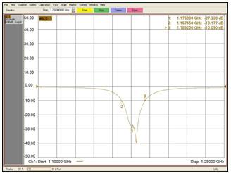
Figure12.S11VsFrequencyCurveofFabricatedAntenna
From the above curve, it is observed that the value for S11 Parameter is-29.752 dB at the resonant frequency of 1.176GHz.
Figure13.FrequencyBandwidthCurveofFabricatedAntenna
From the above curve, it is observed that the frequency bandwidth falls within the range of 1.167GHz to 1.186GHz.

InternationalJournalofAntennas(JANT)Vol.3,No.1/2/3,July2017 10
Figure14.VSWRVsFrequencycurveofFabricatedAntenna
From the above curve, it is inferred that the Voltage Standing Wave Ratio (VSWR) of1.03 is obtained at the frequency of 1.176GHz.
9. COMPARISON OF SIMULATION RESULTS VS EXPERIMENTAL RESULTS
For Patch dimensions of L=81.8mm and W=82.7mm and at feed point X=11 and Y=-13, the antenna parameters are compared between simulated results and experimental results.

Table3.ComparisonofSimulationResultsandExperimentalResults
Sl.No AntennaParameters
SimulatedResults ExperimentalResults
1 S11 -27.439dB -29.752dB
VoltageStanding WaveRatio(VSWR) 1.088 1.0327
AntennaGain 6.25dB 6.3dB
AxialRatio 0.37 3.95 5 Bandwidth 1.176GHzto 1.186GHz 1.167GHzto 1.186GHz
From the above table, it is observed that the Experimental values of fabricated antenna are in proximal to the simulated results.
10. CONCLUSION
A Rectangular Microstrip Patch Antenna, resonant at frequency fo = 1.176GHz, is designed and simulated on glass epoxy FR-4 substrate. The microstrip patch dimensions obtained from the simulation are used to fabricate the antenna. The simulation of rectangular Microstrip Patch antenna with coaxial feeding technique is performed by using IE3D software for the specific frequency of 1.176 GHz. The feed point was varied to arrive at the point of minimum return loss and at the feed location of X=11 and Y=-13, the S11 value of -27.439dB and axial ratio of 0.37dB was obtained and the same was compared to the measured values of the fabricated antenna.
InternationalJournalofAntennas(JANT)Vol.3,No.1/2/3,July2017 11
2
3
4
InternationalJournalofAntennas(JANT)Vol.3,No.1/2/3,July2017
REFERENCES
[1] N.Herscovici.1998.Newconsiderationsinthedesignofmicrostripantennas.IEEETransactionson AntennasandPropagation,AP-46,6(Jun.1998),807-812.
[2] D. Sanchez-Hernandez and I. D. Robertson. 1996. A Survey of Broad band Micro strip Patch Antennas.MicrowaveJournal,(Sep.1996),60-84.
[3] DipakK.Neog,ShyamS.Pattnaik,Dhruba.C.Panda,SwapnaDevi,BonomaliKhuntia,andMalaya Dutta, “Design of a Wideband Micro strip Antenna and the Use of Artificial Neural Networks in ParameterCalculation”,IEEEAntennasandPropagationMagazine,Vol.47,No.3,June2005.
[4] C.A.Balanis,AntennaTheory,AnalysisandDesign,JohnWileyandSons,NewYork.
[5] Prof. Mahesh M. Gadag, Mr. Dundesh S. Kamshetty, Mr. SureshL. Yogi “Design of Different Feeding Techniques of Rectangular Micro strip Antenna for 2.4GHz RFID Applications Using IE3D”,Proc.oftheIntl.Conf.onAdvancesinComputer,ElectronicsandElectricalEngineering.
[6] www.mtiwe.com
[7] Jagdish. M. Rathod, Member, IACSIT, IETE (I), IE (I), BES (I)“Comparative Study of Micro strip Patch Antenna for Wireless Communication Application”, International Journal of Innovation, ManagementandTechnology,Vol.1,No.2,June2010ISSN:2010-0248
[8] www.antennatheory.com
[9] Antennas(fromtheorytoPractice)-YiHuangandKevinBoyle
AUTHORS
Aishwarya Sudarsan is currently pursuing her Bachelor's degree in Electronic and communication Engineering in New Horizon College of Engineering at Bangalore, INDIA. Her research Interests include Antennas, VLSI, Embedded Systems and power electronics. She presented many papers in technical seminars andsymposiums.

12