
Inverted F Antenna (PIFA) For Mobile Handset Applications
K. Rama Krishna1, G Sambasiva Rao2, P.R.Ratna Raju.K3 V R Siddhartha Engineering college1, India Madanapalle Institute of Technology and Science2,3, IndiaABSTRACT
In this paper dual band Planar Inverted F Antenna (PIFA) is presented for mobile handset applications at dual frequencies. PIFA is a flat structure, simple and easy to fabricate. The idea of U-shaped slot technique is introduced into the basic rectangular patch antenna for higher GSM frequency. The impedance bandwidth covers GSM 900 and GSM 1900 bands. The PIFA covers a bandwidth of 31.9MHz (0.880.911GHz) or about 3.5% with respect to the resonance frequency at 0.89GHz. For the higher resonant mode the impedance bandwidth is 112.7MHz (1.873-1.985GHz) or about 5.83% with respect to resonance frequency of 1.93 GHz. The PIFA has a gain of 2.59dB and 5.12dB at lower and higher resonating frequencies respectively. PIFA is analyzed using High Frequency Structure Simulator (HFSS).
KEYWORDS
Planar Inverted F antenna, Return loss, GSM 900, GSM1900
1.INTRODUCTION
For rapid development of Cellular Communication an antenna which meets the requirement of a mobile phone user is very demanding. Monopole ß/2 antenna was used earlier to face these challenges. Half wavelength monopole antennas have high radiation towards user head, easy to physical damage and unable to produce multi resonance frequencies. Later monopole antenna is replaced by Planar Inverted F Antenna (PIFA). It has advantages of desired cross polarization in order to receive both horizontal and vertical polarization, easy feeding, simple to fabricate and easy to place in mobile terminal as its size is less (ß/4). It has less spurious radiation towards user head.Planar Inverted F antenna is a radiating element shorted at one end from patch to ground. This shorting plate makes the PIFA to resonate at ß/4. In present scenario minimum size of the antenna is challenging one. For PIFA with ß/4 resonance, same basic properties can be obtained as that of normal half wavelength patch antenna.
2.PLANAR INVERTED F ANTENNA (PIFA)
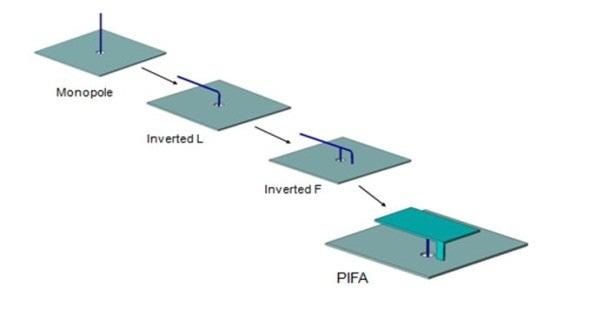
Planar Inverted F antenna is developed from mono pole antenna. Inverted L is realized by folding down the mono pole in order to decrease the height of the antenna at the same time maintaining identical resonating length. When feed is applied to the Inverted L, the antenna appears as
InternationalJournalofAntennas(JANT)Vol.1,No.1,October2015
37
DOI:10.5121/jant.2015.1104
Inverted F. The thin top wire of Inverted F is replaced by planar element to get the Planar Inverted F antenna. This sequence is clearly observable in Fig
thin wire Inverted planar to This in Fig1.
Fig1.PIFAfrommonopole
2.1 PIFA DESIGN

PIFA consists of ground plane, radiating patch coaxial probe feed is given between the ground plane is folded at one edge of a patch and length as shown in Fig 2. The size of the patch and resonating frequency can be determined by the following equations
PIFA plane, patch above the ground plane and shorting plane. A is the plane and patch element. Top radiating patch one of patch shorted to the ground plane to decrease the antenna 2. The (1)
Fig2. BasicPIFA (2) (3)
shorting element. radiating to the = Width the vertical


of patch, L2 = Width of the patch, C = Velocity of light, = dielectric = wavelength. PIFA has moderate (or) n. Generally of wireless systems use vertical polarization. Even if transmitter polarization is not still the strength. fixed, (greater than dB) is received and signal summing verticalcomponents.
Where L1 = length of the patch, constant,ß = wavelength. PIFA has moderate (or) high gain in both horizontal and vertical polarization. Generally most of the wireless antenna polarization is not known, still the signal is received with good strength. When antenna orientation is not fixed, a signal with good gain (greater than 10 dB) strength is calculated by summing up the horizontal and vertical
InternationalJournalofAntennas(JANT)Vol.1,No.1,October2015
38
InternationalJournalofAntennas(JANT)Vol.1,No.1,October2015
3.ANTENNA DESCRIPTION
The design of the proposed antenna is shown in Fig 3. It consists of patch plane, ground plane, shorting plate and feeding post connected to the ground plane. Between dielectric medium and patch plate, air is placed. Resonating frequency can be calculated if the initial patch and shorting pin sizes are known using Eq (3).
The dimensions of PIFA are 22mm × 40 mm and is located 5mm above the phone printed circuit board (PCB).The PCB layer has relative permittivity of 4.4 (FR4_epoxy ) with size 100×40×1.2 mm. To provide RF ground, PCB is metalized on its back surface. By using optimization, the PIFA is operated at resonant frequencies of 0.89GHz and 1.93GHz to cover the dual band of GSM900 and GSM1900. The proposed antenna is fed by microstrip feeding structure. U-shaped slot is introduced on patch plane in order to get dual resonance. Basically coaxial probe feed is used for PIFA. Here in this antenna Microstrip line feed of width 2mm is used as shown in Fig3.
Fig3. PIFAdesign
Two folded patches are introduced in order to get the high gain at resonant frequencies. First folded patch of dimension 17 mm × 4 mm is introduced along the width of the patch. Similarly second folded patch of dimension 18 mm × 3mm is introduced along the length side of rectangular patch.
Antenna geometry is shown in Table 1 and Antenna description is shown in Table2
Table1:PIFAparameters
Lengthofthepatch(L1) 40mm
Widthofthepatch(L2) 22mm
Widthoftheshortingpin(W) 6.7mm
Heightofthesubstrate(h sub ) 1.2mm
Lengthofthegroundplane 100mm Widthofthe groundplane 40mm
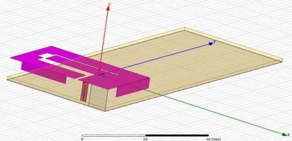
Table2:Antennadescription
Shape Rectangular Frequencyof operation
GSM900(880960)MHz GSM1900(18501990)MHz
Dielectricconstant ofthesubstrate FR4Epoxy(4.4)
39
InternationalJournalofAntennas(JANT)Vol.1,No.1,October2015
Heightofthe dielectricsubstrate 1.2mm Feedingmethod Microstripfeed VSWR 2:1 Gain (2-6)dB
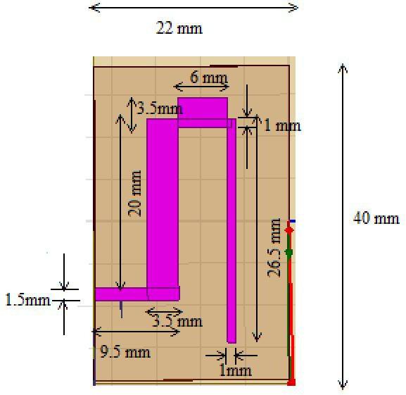
The dimensions of different slots are clearly mentioned in the top view of antenna as shown in Fig 4.
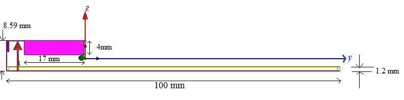
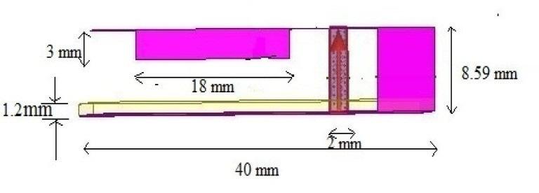
Fig4.TopviewofPIFA
Fig5.FrontView
4.SIMULATION RESULTS Fig6.SideView
The Planar Inverted F antenna was analyzed and optimized with the HFSS 13 simulator software. Since generally PIFA is a high frequency device driven model is used while designing antenna in HFSS software.
40
4.1The effect of slot on patch for PIFA
The U-shaped slot on patch plane makes the PIFA antenna resonating at dual frequencies. Initially U-shaped slot is introduced on patch plane. Dual resonating frequencies are generated out of GSM range. Using parametric analysis that is by varying the length and width of U-shaped slot dual resonating frequencies are obtained in the GSM range.
For dimensions as shown in Fig 5 (Top view) of PIFA, dual resonating frequencies are obtained at 0.89GHz and 1.93GHznin the GSM 900 and GSM 1900 standards with return loss of -33.36dB and -29.67dB respectively.
4.2 Return loss
The lesser return loss the more properly antenna radiating. -10dB value can be considered as the acceptable return loss. For bandwidth calculations -10db is considered as acceptable return loss. The return loss of a PIFA with normal microstrip feed is -33.36dB and -29.6dB at frequencies 0.89GHz and 1.93GHz respectively as shown in Fig 7.
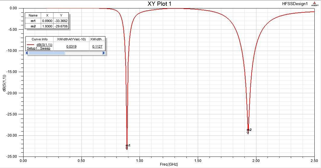
Fig7. ReturnlossofPIFA
The impedance bandwidth is 31.9MHz (0.88-0.911GHz) or about 3.5% with respect to the resonance frequency at 0.89GHz. For the higher resonant mode the impedance bandwidth is 112.7MHz (1.873-1.985GHz), or about 5.83% with respect to resonance frequency of 1.93 GHz. The acquired bandwidths can sufficiently cover the bandwidth requirement for GSM 900 and GSM 1900 standards.
4.3 VSWR
Voltage standing wave ratio (VSWR) should be 2:1 for good radiator. A maximum gain of 2.59 dB is achieved in lower band with VSWR value of 1.0439 indicating a good impedance matching (perfect matching VSWR=1) which implies that almost all input power could be transmitted to the patch. In the higher band, the peak gain reaches to 5.12dB with VSWR value of 1.06 indicating a good impedance matching. For both higher and lower bandwidths range the VSWR is 2:1 as shown in Fig 8.
InternationalJournalofAntennas(JANT)Vol.1,No.1,October2015 41
Fig8. VSWRofPIFA
4.4 The effect of shorting plane width
The effect of shorting plane (shorting pin) width can be analyzed using parametric analysis. As short plane width increases from 2mm to 6.7mm, the return loss increases at lower & higher bands and return loss curves are shifting right side of the graph or resonating frequencies are increased as shown in Fig 12. Resonating frequency of PIFA can be determined using Eq (3). Return loss variation for different short plane widths are as shown in Table4.
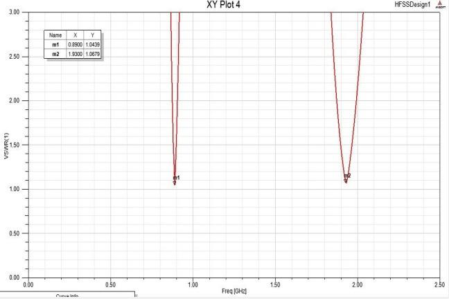
Fig9:Variationofreturnloss withfrequencyfordifferentshortplanewidth Table4:shortplane widthVS Returnloss
Shorting plane width(sh_w) Return Loss (dB) at lower band(0.89GHz)

Return Loss(dB) at higher band(1.93GHz)
2mm -12.29 -14.8 4mm -20.04 -20.211 6mm -21.8455 -25.6733 6.7mm -33.3652 -29.6705
42
InternationalJournalofAntennas(JANT)Vol.1,No.1,October2015
4.5 The effect of substrate height
The effect of substrate height can be analyzed using parametric analysis. As substrate height increases from 1.2mm to 4.4mm, impedance bandwidth and return loss at lower and higher bands are decreasing and the return loss curve moving left side of the graph. The variation of return loss and impedance bandwidth is tabulated as shown in Fig 10.
Fig10.Returnlosscorrespondingtosubstrateheightvariation
Table5:Returnloss&Band widthcorrespondingtosubstrateheightvariation
Substrat e height Sub_w (mm)
Return loss at (0.89GHz) dB
Return loss at (1.93GH) dB
Impedanc e band width at lower band (MHz)
Impedanc e band width at higher band (MHz)

1.2 -33.3652 -29.67 31.9 112.7
1.8 -24.1126 -24.337 30.5 106.5 2.8 -17.2341 -21.0618 25.5 95.8
3.8 -12.115 -17.633 16.6 83.5 4.4 -9.6 -16.56 0 75.5
4.6 The effect of change of dielectric constant ( )
When dielectric constant of the material increases, the lower bandwidth is approximately constant where as the higher bandwidth decreases as shown in Table 6. It is also observed that return loss increases as dielectric constant increases.
43
InternationalJournalofAntennas(JANT)Vol.1,No.1,October2015
InternationalJournalofAntennas(JANT)Vol.1,No.1,October2015
Table6:Theeffectofchange ofdielectricconstant
dielectric constant ( )
Return loss at 0.89GHz (dB)
Return loss at 1.93GHz (dB)
Impedance bandwidth at lower band(MHz)
Impedance bandwidth at higher band(MHz)
2.2 -20.33 -30.89 31.3 116
3.2 -26.31 -29.44 31.4 113.6
4.4 -33.36 -29.67 31.9 112.7
5.RADIATION PATTERN
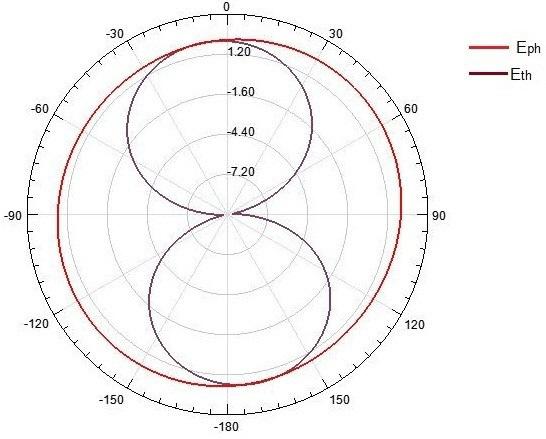
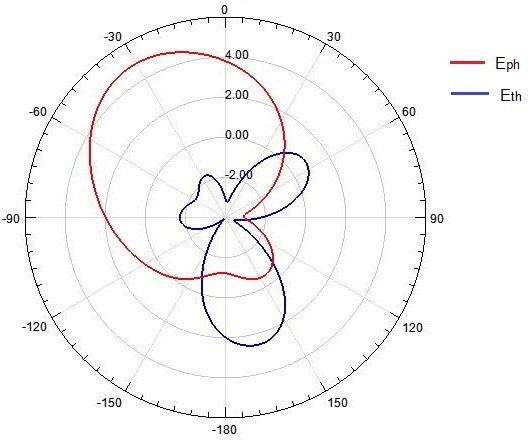
The radiation pattern refers to the directional (angular) dependence of the electric field (magnetic field) strength of the antenna. At lower resonating frequency radiation pattern is omni-directional i.e. radiation pattern is figure 8 pattern in elevation plane and uniform in azimuthal plane as shown in Fig 11 with a gain of 2.59 dB. At higher resonating, the radiation pattern is nearly uniform in azimuthal plane and directional in elevation plane as shown in Fig 12 resembles omni- directional pattern with a gain of 5.12 dB.
Fig11. Radiationpatternforfr = 0.89GHz
44
InternationalJournalofAntennas(JANT)Vol.1,No.1,October2015
Fig12.Radiationpatternforfr =1.93GHz
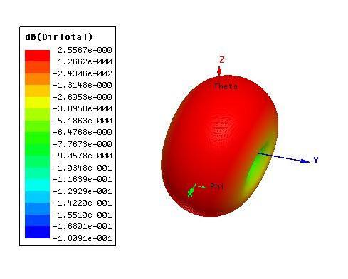
5.1 Directivity
Maximum gain in a given direction is called directivity. If antenna efficiency is one directivity and antenna gain are interchangeable. When resonance frequency is 0.89GHz, a directivity of 2.55dB is achieved as shown in Fig 13. When resonance is frequency 1.93GHz, a directivity of 4.882dB is obtained as shown in Fig 14.
Fig13. Directivityplotforfr =0.89GHz
45
Fig14. Directivityplotforfr =1.93GHz
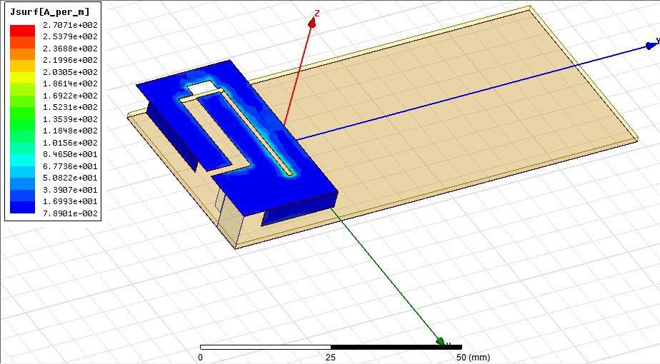
5.2 Surface current distribution
The simulated current distributions on the antenna body for both resonant frequencies are represented in Fig 15. At both resonating frequencies, the current distribution has a maximum close to the shorting pin similar to the standard PIFA. It is clearly observed from the Fig 15(a) that the radiation is more at the slots at 0.89 GHz with a maximum value of surface current distribution (A/m) of more than 0.27 X10³ A/m. For the higher resonant frequency, the magnitude of surface current is observed to be less than the current distribution at lower resonant frequency as shown in Fig 15(b).
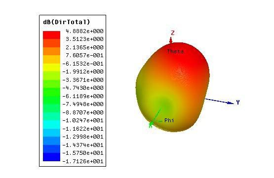
Fig15(a):Surfacecurrentdistributionat0.89GHz
46
InternationalJournalofAntennas(JANT)Vol.1,No.1,October2015
InternationalJournalofAntennas(JANT)Vol.1,No.1,October2015
Fig15(b):Surfacecurrentdistributionat1.93GHz
6.CONCLUSION
In this project Planar Inverted Antenna (PIFA) is designed and simulated. The PIFA covers a bandwidth of 31.9MHz (0.88-0.911GHz) and 112.7MHz (1.873-1.985GHz) and lower and higher bands with directivity of 2.55dB and 4.88dB at lower and higher resonating frequencies 0.89GHz and 1.93GHz respectively.

REFERENCES
[1] Saad Wasmi Luhaib, Kaydar M. Quboa and Bareq M. Abaoy "Design and Simulation Dual-Band PIFAAntennaforGSMSystems”9thinternational multiconferenceonsystems2012.
[2] Z. D. Liu, P. S.Hall, andD. Wake,"Dual-FrequencyPlanar Inverted-F Antenna", IEEE Trans. AntennasPropagation,Vol.45, No.10,pp.1451-1458,Oct.1997.
[3] M.Komulainen, M. Berg, H. Jantunen, E. T. Salonen," A Frequency Tuning Method for a Planar Inverted-F Antenna",IEEETrans. AntennasPropagat,Vol.56,No.4,April2008.
[4] P. Nepa, G. Manara, A.A. Serra, g. Nenna. “Multiband PIFA for WLAN mobile terminals”, IEEEAntennasWirelessPropagat Letters,2005,vol.4,pp.349–350.
[5] S.-H. Yeh, K.-L. Wong,T.-W. Chiou, and S.T. Fang, "Dual-band planar inverted F antenna for GSM/DCS mobile phones," IEEE Trans. Antennas Propagat, vol. 51, no. 5, pp. 1124-1126, May 2003.
[6] AdnanIftikhar,MuhammadNadeemRaftiq,"ADual bandbalancedplanarinvertedFantenna(PIFA) for mobile applications” IEEE Proc-Microwave, Antennas Propagation, Vol.149, No,2,pp. 8591,2013
[7] Dongsheng Qi, Binhong Li, and Haitao Liu "Compact triple-band planar inverted-F antenna for mobile handsets", Microwave and OpticalTechnologyLetters,Vol.41,No.6,June20,2004.
[8] P. Salonen, M. Keskilammi, and M. Kivikoski, "Single-Feed Dual-Band Planar Inverted-F Antenna withU-ShapedSlot",IEEETrans. AntennasandPropagat.,Vol.48,No.8,pp.1262-1264,Aug. 2000.
[9] N. Misran, M. M. Yunus and M.T. Islam, “Small Dual-Band Planar Antenna with Folded Patch Feed",JournalofAppliedSciencesResearch,6(12),2010.
[10] Sandeep K Veeravalli, K.Shambavi, Zachariah C Alex “Design of Multi band Antenna for Mobile Hand set”, Proceedings of 2013 IEEE conference on Information and Communication Technologies (ICT 2013).
[11] ”Antennas forallapplications”3rdeditionbyJohnDKrauss
[12]“Antennathoeryanalysis &Design”,3rdeditionbyConstantine A.Balanis
[13] Highfrequencystructure simulator(HFSS)13version.
47
Authors
G Sambasiva Rao was born in india, A.P in 1984. He received B.E(ECE) from Narasaraopeta Engineering College, Narasaraopeta. And M.Tech(Microwave Engg) from University of Kerala, Trivandrum. He has a 6 years of teaching experience. 4 International Journals, 02 International Conference in his credit. Presently working as an Assistant professorinMITS,Madanapalle,A.P

P.R.Ratna Raju.K was born in india, A.P in 1984. He received B.E(ECE) from Sir C.R.Reddy College of Engineering, Eluru. And M.Tech(Communication systems) SVNIT, Surat, Gujarat .He has a 6 years of teaching experience. Presently working as an Assis tant professorinMITS,Madanapalle,A.P
K Ramakrishna was born in india, A.P in 1988. He received B.E(ECE) and M.Tech(Microwave Engg) from VR Siddhartha Engineering College, Vijayawada. He has a 2 years of teaching experience. 1 International Journals, 02 International Conference in his credit. Presently working as an Assistant professorinSrinidhiinstituteTechnolog,Hyderabad,Telangana.

48
InternationalJournalofAntennas(JANT)Vol.1,No.1,October2015