Electric Circuits 10th Edition Nilsson Solutions Manual Visit to Download in Full: https://testbankdeal.com/download/electric-circuits-10th-editi on-nilsson-solutions-manual/

AP2.1
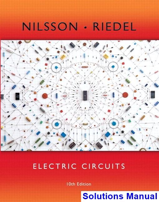
[a]Notethatthecurrent ib isinthesamecircuitbranchasthe8Acurrent source;however, ib isdefinedintheoppositedirectionofthecurrent source.Therefore,
ib = 8A
Next,notethatthedependentvoltagesourceandtheindependent voltagesourceareinparallelwiththesamepolarity.Therefore,their voltagesareequal,and
vg = ib 4 = 8 4 = 2 V
[b]Tofindthepowerassociatedwiththe8Asource,weneedtofindthe voltagedropacrossthesource, vi.Notethatthetwoindependentsources areinparallel,andthatthevoltages vg and v1 havethesamepolarities, sothesevoltagesareequal:
vi = vg = 2V
Usingthepassivesignconvention, ps =(8A)(vi)=(8A)( 2V)= 16W
Thusthecurrentsourcegenerated16Wofpower.
AP2.2
AP2.3
[a]Notefromthecircuitthat vx = 25V.Tofind α notethatthetwo currentsourcesareinthesamebranchofthecircuitbuttheircurrents flowinoppositedirections.Therefore
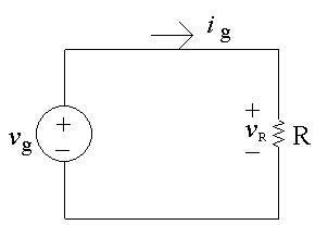
αvx = 15A
Solvetheaboveequationfor α andsubstitutefor vx,
α = 15A vx = 15A 25V =0.6A/V
[b]Tofindthepowerassociatedwiththevoltagesourceweneedtoknowthe current, iv .Notethatthiscurrentisinthesamebranchofthecircuitas thedependentcurrentsourceandthesetwocurrentsflowinthesame direction.Therefore,thecurrent iv isthesameasthecurrentofthe dependentsource:
iv = αvx =(0.6)( 25)= 15A
Usingthepassivesignconvention, ps = (iv )(25V)= ( 15A)(25V)=375W
Thusthevoltagesourcedissipates375W.
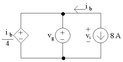
[a]Theresistorandthevoltagesourceareinparallelandtheresistorvoltage andthevoltagesourcehavethesamepolarities.Thereforethesetwo voltagesarethesame:
vR = vg =1kV
AP2.4
Notefromthecircuitthatthecurrentthroughtheresistoris ig =5mA. UseOhm’slawtocalculatethevalueoftheresistor:
R = vR ig = 1 kV 5mA = 200kΩ
Usingthepassivesignconventiontocalculatethepowerintheresistor,
pR =(vR)(ig)=(1kV)(5mA)=5W Theresistorisdissipating5Wofpower.
[b]Notefrompart(a)the vR = vg and iR = ig .Thepowerdeliveredbythe sourceisthus
psource = vgig so vg = psource ig = 3 W 75mA = 40V
Sincewenowhavethevalueofboththevoltageandthecurrentforthe resistor,wecanuseOhm’slawtocalculatetheresistorvalue:
R = vg ig = 40V 75mA = 533 33Ω
Thepowerabsorbedbytheresistormustequalthepowergeneratedby thesource.Thus,
pR = psource = ( 3W)=3W
[c]Again,notethe iR = ig.Thepowerdissipatedbytheresistorcanbe determinedfromtheresistor’scurrent:
pR = R(iR)2 = R(ig )2
Solvingfor ig ,
i2 g = pr R = 480mW 300Ω = 0.0016so ig = √0.0016=0.04A=40mA
Then,since vR = vg
vR = RiR = Rig =(300Ω)(40mA)=12Vso vg =12V
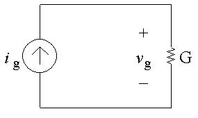
[a]Notefromthecircuitthatthecurrentthroughtheconductance G is ig , flowingfromtoptobottom,becausethecurrentsourceandthe
conductanceareinthesamebranchofthecircuitsomusthavethesame current.Thevoltagedropacrossthecurrentsourceis vg,positiveatthe top,becausethecurrentsourceandtheconductancearealsoinparallel somusthavethesamevoltage.FromaversionofOhm’slaw,
vg = ig G = 0 5 A 50mS = 10V
Nowthatweknowthevoltagedropacrossthecurrentsource,wecan findthepowerdeliveredbythissource:
psource = vgig = (10)(0.5)= 5W
Thusthecurrentsourcedelivers5Wtothecircuit.
[b]Wecanfindthevalueoftheconductanceusingthepower,andthevalue ofthecurrentusingOhm’slawandtheconductancevalue:
[c]Wecanfindthevoltagefromthepowerandtheconductance,andthen usethevoltagevalueinOhm’slawtofindthecurrent:
= 40,000=200V
AP2.5 [a] Redrawthecircuitwithallofthevoltagesandcurrentslabeledforevery circuitelement.
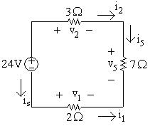
WriteaKVLequationclockwisearoundthecircuit,startingbelowthe voltagesource:
24V+ v2 + v5 v1 =0
Next,useOhm’slawtocalculatethethreeunknownvoltagesfromthe threecurrents:
AKCLequationattheupperrightnodegives i2 = i5;aKCLequationat thebottomrightnodegives i5 = i1;aKCLequationattheupperleft nodegives is = i2.Nowreplacethecurrents i1 and i2 intheOhm’slaw equationswith i5:
v2 =3i2 =3i5; v5 =7i5; v1 =2i1 = 2i5
Nowsubstitutetheseexpressionsforthethreevoltagesintothefirst equation:
24= v2 + v5 v1 =3i5 +7i5 ( 2i5)=12i5 Therefore i5 =24/12=2A
[b] v1 = 2i5 = 2(2)= 4V
[c] v2 =3i5 =3(2)=6V
[d] v5 =7i5 =7(2)=14V
[e]
AKCLequationatthelowerleftnodegives is = i1.Since i1 = i5, is = 2A.Wecannowcomputethepowerassociatedwiththevoltage source:
p24 =(24)is =(24)( 2)= 48W
Therefore24Vsourceisdelivering48W.
AP2.6Redrawthecircuitlabelingallvoltagesandcurrents:
Wecanfindthevalueoftheunknownresistorifwecanfindthevalueofits voltageanditscurrent.Tostart,writeaKVLequationclockwisearoundthe rightloop,startingbelowthe24Ωresistor:
120V+ v3 =0
UseOhm’slawtocalculatethevoltageacrossthe8Ωresistorintermsofits current:
v3 =8i3
Substitutetheexpressionfor v3 intothefirstequation:
120V+8i3 =0so i3 = 120 8 = 15A
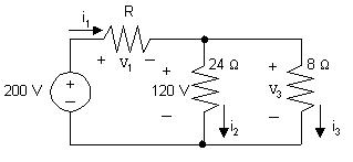
AlsouseOhm’slawtocalculatethevalueofthecurrentthroughthe24Ω resistor:
i2 = 120V 24Ω = 5A
NowwriteaKCLequationatthetopmiddlenode,summingthecurrents leaving:
i1 + i2 + i3 =0so i1 = i2 + i3 =5+15=20A
WriteaKVLequationclockwisearoundtheleftloop,startingbelowthe voltagesource:
200V+ v1 +120V=0so v1 =200 120=80V
Nowthatweknowthevaluesofboththevoltageandthecurrentforthe unknownresistor,wecanuseOhm’slawtocalculatetheresistance:
R= v1 i1 = 80 20 = 4Ω
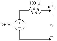
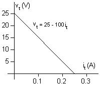
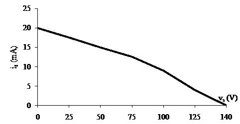
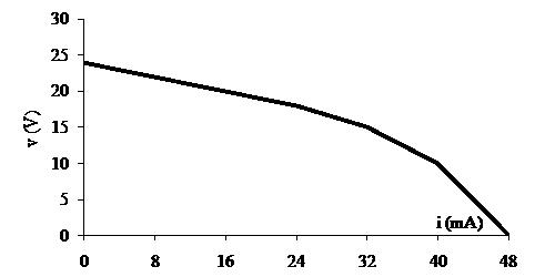
AP2.7 [a] Plottingagraphof vt versus it gives
Notethatwhen it = 0, vt =25V;thereforethevoltagesourcemustbe25 V.Sincetheplotisastraightline,itsslopecanbeusedtocalculatethe valueofresistance:
R = ∆v ∆i = 25 0 0 25 0 = 25 0 25 =100Ω
Acircuitmodelhavingthesame v i characteristicisa25Vsourcein serieswitha100Ωresistor,asshownbelow:
AP2.8 [a]
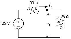
Drawthecircuitmodelfrompart(a)andattacha25Ωresistor:
Tofindthepowerdeliveredtothe25Ωresistorwemustcalculatethe currentthroughthe25Ωresistor.DothisbyfirstusingKCLtorecognize thatthecurrentineachofthecomponentsis it,flowinginaclockwise direction.WriteaKVLequationintheclockwisedirection,starting belowthevoltagesource,andusingOhm’slawtoexpressthevoltage dropacrosstheresistorsinthedirectionofthecurrent it flowingthrough theresistors:
25V+100it +25it =0so125it =25so it = 25 125 = 0 2A
Thus,thepowerdeliveredtothe25Ωresistoris
p25 =(25)i2 t =(25)(0.2)2 =1W.
FromthegraphinAssessmentProblem2.7(a),weseethatwhen vt =0, it =0.25A.Thereforethecurrentsourcemustbe0.25A.Sincetheplot isastraightline,itsslopecanbeusedtocalculatethevalueofresistance:
R = ∆v ∆i = 25 0 0.25 0 = 25 0.25 =100Ω
Acircuitmodelhavingthesame v i characteristicisa0.25Acurrent sourceinparallelwitha100Ωresistor,asshownbelow: [b]
Drawthecircuitmodelfrompart(a)andattacha25Ωresistor:


NotethatbywritingaKVLequationaroundtherightloopweseethat thevoltagedropacrossbothresistorsis vt.WriteaKCLequationatthe topcenternode,summingthecurrentsleavingthenode.UseOhm’slaw
tospecifythecurrentsthroughtheresistorsintermsofthevoltagedrop acrosstheresistorsandthevalueoftheresistors.
0.25+ vt 100 + vt 25 = 0, so5vt =25, thus vt =5V
p25 = v2 t 25 = 1W
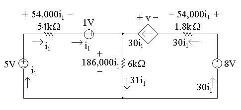
AP2.9Firstnotethatweknowthecurrentthroughallelementsinthecircuitexcept the6kΩresistor(thecurrentinthethreeelementstotheleftofthe6kΩ resistoris i1;thecurrentinthethreeelementstotherightofthe6kΩresistor is30i1).Tofindthecurrentinthe6kΩresistor,writeaKCLequationatthe topnode:
i1 +30i1 = i6k =31i1
WecanthenuseOhm’slawtofindthevoltagesacrosseachresistorinterms of i1.Theresultsareshowninthefigurebelow:
[a] Tofind i1,writeaKVLequationaroundtheleft-handloop,summing voltagesinaclockwisedirectionstartingbelowthe5Vsource:
5V+54,000i1 1V+186,000i1 =0
Solvingfor i1
54,000i1 +186,000i1 =6Vso240,000i1 =6V
Thus, i1 = 6 240,000 =25 µA
[b] Nowthatwehavethevalueof i1,wecancalculatethevoltageforeach componentexceptthedependentsource.ThenwecanwriteaKVL equationfortheright-handlooptofindthevoltage v ofthedependent source.Sumthevoltagesintheclockwisedirection,startingtotheleftof thedependentsource:
+v 54,000i1 +8V 186,000i1 =0
Wenowknowthevaluesofvoltageandcurrentforeverycircuitelement. Let’sconstructapowertable:
[c] Thetotalpowergeneratedinthecircuitisthesumofthenegativepower valuesinthepowertable:
Thus,thetotalpowergeneratedinthecircuitis6150 µW.
[d] Thetotalpowerabsorbedinthecircuitisthesumofthepositivepower valuesinthepowertable:
Thus,thetotalpowerabsorbedinthecircuitis6150 µW.
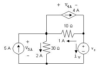
AP2.10Giventhat iφ =2A,weknowthecurrentinthedependentsourceis 2iφ =4A.WecanwriteaKCLequationattheleftnodetofindthecurrentin the10Ωresistor.Summingthecurrentsleavingthenode,
5A+2A+4A+ i10Ω =0so i10Ω =5A 2A 4A= 1A
Thus,thecurrentinthe10Ωresistoris1A,flowingrighttoleft,asseenin thecircuitbelow.
[a] Tofind vs,writeaKVLequation,summingthevoltagescounter-clockwise aroundthelowerrightloop.Startbelowthevoltagesource.
vs +(1A)(10Ω)+(2A)(30Ω)=0so vs =10V+60V=70V
[b] ThecurrentinthevoltagesourcecanbefoundbywritingaKCLequation attheright-handnode.Sumthecurrentsleavingthenode
4A+1A+ iv =0so iv =4A 1A=3A
Thecurrentinthevoltagesourceis3A,flowingtoptobottom.The powerassociatedwiththissourceis
p = vi =(70V)(3A)=210W
Thus,210Wareabsorbedbythevoltagesource.
[c] Thevoltagedropacrosstheindependentcurrentsourcecanbefoundby writingaKVLequationaroundtheleftloopinaclockwisedirection:
v5A +(2A)(30Ω)=0so v5A =60V
Thepowerassociatedwiththissourceis
p = v5Ai = (60V)(5A)= 300W
Thissourcethusdelivers300Wofpowertothecircuit.
[d] Thevoltageacrossthecontrolledcurrentsourcecanbefoundbywritinga KVLequationaroundtheupperrightloopinaclockwisedirection:
+v4A +(10Ω)(1A)=0so v4A = 10V
Thepowerassociatedwiththissourceis
p = v4Ai =( 10V)(4A)= 40W
Thissourcethusdelivers40Wofpowertothecircuit.
[e] Thetotalpowerdissipatedbytheresistorsisgivenby (i30Ω)2(30Ω)+(i10Ω)2(10Ω)=(2)2(30Ω)+(1)2(10Ω)=120+10=130W
P2.1 [a] Yes,independentvoltagesourcescancarrythe5Acurrentrequiredbythe connection;independentcurrentsourcecansupportanyvoltagerequired bytheconnection,inthiscase5V,positiveatthebottom.
[b] 20Vsource:absorbing
15Vsource:developing(delivering)
5Asource:developing(delivering)
[c] P20V =(20)(5)=100W(abs)
P15V = (15)(5)= 75W(dev/del)
P5A = (5)(5)= 25W(dev/del)
Pabs = Pdel =100W
[d] Theinterconnectionisvalid,butinthiscircuitthevoltagedropacrossthe 5Acurrentsourceis35V,positiveatthetop;20Vsourceisdeveloping (delivering),the15Vsourceisdeveloping(delivering),andthe5A sourceisabsorbing:
P20V = (20)(5)= 100W(dev/del)
P15V = (15)(5)= 75W(dev/del)
P5A =(35)(5)=175W(abs)
Pabs = Pdel =175W
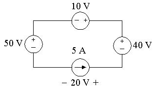
P2.2Theinterconnectisvalidsincethevoltagesourcescanallcarry5Aofcurrent suppliedbythecurrentsource,andthecurrentsourcecancarrythevoltage droprequiredbytheinterconnection.Notethatthebranchcontainingthe10 V,40V,and5Asourcesmusthavethesamevoltagedropasthebranch containingthe50Vsource,sothe5Acurrentsourcemusthaveavoltage dropof20V,positiveattheright.Thevoltagesandcurrentsaresummarize inthecircuitbelow:
P50V =(50)(5)=250W(abs)
P10V =(10)(5)=50W(abs)
P40V = (40)(5)= 200W(dev)
P5A = (20)(5)= 100W(dev)
Pdev =300W
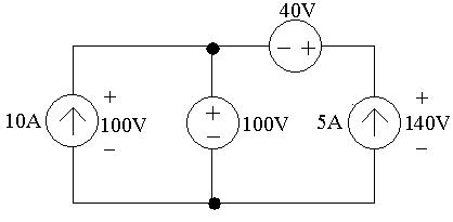
P2.3Theinterconnectionisvalid.The10Acurrentsourcehasavoltagedropof 100V,positiveatthetop,becausethe100Vsourcesuppliesitsvoltagedrop acrossapairofterminalssharedbythe10Acurrentsource.Therighthand branchofthecircuitmustalsohaveavoltagedropof100Vfromtheleft terminalofthe40Vsourcetothebottomterminalofthe5Acurrentsource, becausethisbranchsharesthesameterminalsasthe100Vsource.This meansthatthevoltagedropacrossthe5Acurrentsourceis140V,positiveat thetop.Also,thetwovoltagesourcescancarrythecurrentrequiredofthe interconnection.Thisissummarizedinthefigurebelow:
Fromthevaluesofvoltageandcurrentinthefigure,thepowersuppliedbythe currentsourcesiscalculatedasfollows:
P10A = (100)(10)= 1000W(1000Wsupplied)
P5A = (140)(5)= 700W(700Wsupplied)
Pdev =1700W
P2.4Theinterconnectionisnotvalid.Notethatthe3Aand4Asourcesareboth connectedinthesamebranchofthecircuit.Avalidinterconnectionwould requirethesetwocurrentsourcestosupplythesamecurrentinthesame direction,whichtheydonot.
P2.5Theinterconnectionisvalid,sincethevoltagesourcescancarrythecurrents suppliedbythe2Aand3Acurrentsources,andthecurrentsourcescan carrywhatevervoltagedropfromthetopnodetothebottomnodeisrequired bytheinterconnection.Inparticular,notethethevoltagedropbetweenthe topandbottomnodesintherighthandbranchmustbethesameasthe voltagedropbetweenthetopandbottomnodesinthelefthandbranch.In particular,thismeansthat
Henceanycombinationof v1 and v2 suchthat v1 + v2 = 4Visavalid solution.
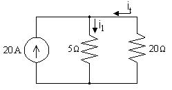
P2.6 [a] Becausebothcurrentsourcesareinthesamebranchofthecircuit,their valuesmustbethesame.Therefore,
v1 50 = 0 4 → v1 =0 4(50)=20V
[b]
p = v1(0 4)=(20)(0 4)=8W(absorbed)
P2.7 [a] Thevoltagedropfromthetopnodetothebottomnodeinthiscircuit mustbethesameforeverypathfromthetoptothebottom.Therefore, thevoltagesofthetwovoltagesourcesareequal:
αi∆ =6
Also,thecurrent i∆ isinthesamebranchasthe15mAcurrentsource, butintheoppositedirection,so
i∆ = 0.015
Substituting,
α( 0.015)=6 → α = 6 0 015 =400 Theinterconnectionisvalidif α =400V/A.
[b] Thevoltageacrossthecurrentsourcemustequalthevoltageacrossthe6 Vsource,sincebothareconnectedbetweenthetopandbottomnodes. Usingthepassivesignconvention,
p = vi =(6)(0.015)=0.09=90mW
[c] Sincethepowerispositive,thecurrentsourceisabsorbingpower.
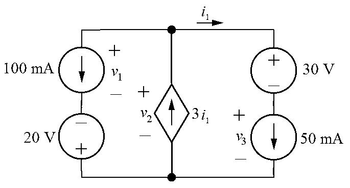
P2.8 [a] Yes,eachofthevoltagesourcescancarrythecurrentrequiredbythe interconnection,andeachofthecurrentsourcescancarrythevoltage droprequiredbytheinterconnection.(Notethat i1 =50mA.)
[b] No,becausethevoltagedropbetweenthetopterminalandthebottom terminalcannotbedetermined.Forexample,define v1, v2,and v3 as shown:
Thevoltagedropacrosstheleftbranch,thecenterbranch,andtheright branchmustbethesame,sincethesebranchesareconnectedatthesame twoterminals.Thisrequiresthat
v1 20= v2 = v3 +30
Butthisequationhasthreeunknownvoltages,sotheindividualvoltages cannotbedetermined,andthusthepowerofthesourcescannotbe determined.
P2.9Theinterconnectionisinvalid.Inthemiddlebranch,thevalueofthecurrent ix mustbe50mA,sincethe50mAcurrentsourcesuppliescurrentinthis branchinthesamedirectionasthecurrent ix.Therefore,thevoltagesupplied bythedependentvoltagesourceintherighthandbranchis1800(0 05)=90
V.Thisgivesavoltagedropfromthetopterminaltothebottomterminalin therighthandbranchof90+60=150V.Butthevoltagedropbetweenthese sameterminalsinthelefthandbranchis30V,duetothevoltagesourcein thatbranch.Therefore,theinterconnectionisinvalid.
P2.10
First,10va = 5V,so va =0.5V.Thenrecognizethateachofthethree branchesisconnectedbetweenthesametwonodes,soeachofthesebranches musthavethesamevoltagedrop.Thevoltagedropacrossthemiddlebranch is5V,andsince va =0.5V, vg =0.5 5= 4.5V.Also,thevoltagedrop acrosstheleftbranchis5V,so20+ v9A =5V,and v9A = 15V,where v9A ispositiveatthetop.Notethatthecurrentthroughthe20Vsourcemustbe 9A,flowingfromtoptobottom,andthecurrentthroughthe vg is6Aflowing fromtoptobottom.Let’sfindthepowerassociatedwiththeleftandmiddle branches:
p9A =(9)( 15)= 135W
p20V =(9)(20)=180W
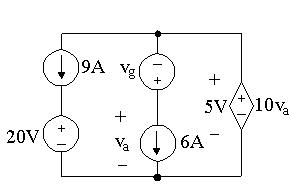
pvg = (6)( 4.5)=27W
p6A =(6)(0.5)=3W
Sincethereisonlyonecomponentleft,wecanfindthetotalpower:
ptotal = 135+180+27+3+ pds =75+ pds =0
so pds mustequal 75W.
Therefore,
P2.11 [a] UsingthepassivesignconventionandOhm’slaw, v = Ri =(3000)(0 015)=45V
[b] PR = v2 R = 452 3000 = 0 675=675mW
[c] Usingthepassivesignconventionwiththecurrentdirectionreversed, v = Ri = (3000)(0.015)= 45V
PR = v2 R = 452 3000 = 0 675=675mW
P2.12 [a] UsingthepassivesignconventionandOhm’slaw, i = v R = 40 2500 = 0.016= 16mA
[b] PR = Ri2 =(2500)( 0.016)2 =0.64=640mW
[c] Usingthepassivesignconventionwiththevoltagepolarityreversed, i = v R = 40 2500 = 0.016=16mA
PR = Ri2 =(2500)(0 016)2 =0 64=640mW
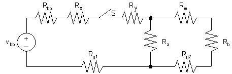
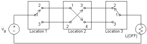
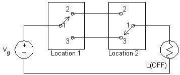
P2.13 [a]
[b] Vbb =no-loadvoltageofbattery
Rbb =internalresistanceofbattery
Rx =resistanceofwirebetweenbatteryandswitch
Ry =resistanceofwirebetweenswitchandlampA
Ra =resistanceoflampA
Rb =resistanceoflampB
Rw =resistanceofwirebetweenlampAandlampB
Rg1 =resistanceofframebetweenbatteryandlampA
Rg2 =resistanceofframebetweenlampAandlampB
S =switch
P2.14Sinceweknowthedeviceisaresistor,wecanuseOhm’slawtocalculatethe resistance.FromFig.P2.14(a),
P2.15Sinceweknowthedeviceisaresistor,wecanusethepowerequation.From
P2.16Theresistorvalueistheratioofthepowertothesquareofthecurrent:
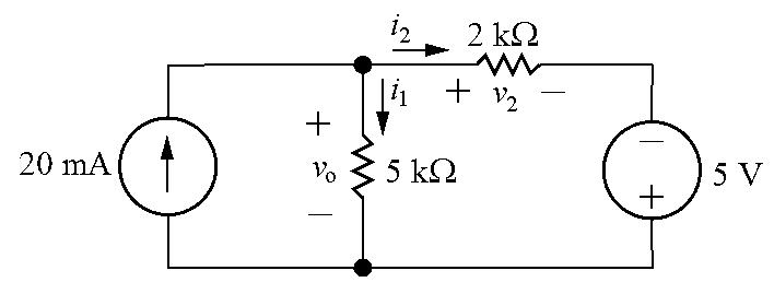
P2.17Labeltheunknownresistorcurrentsandvoltages:
[a]
KCLatthetopnode:0 02= i1 + i2

KVLaroundtherightloop: vo + v2 5=0
UseOhm’slawtowritetheresistorvoltagesinthepreviousequationin termsoftheresistorcurrents:
MultiplytheKCLequationby
Solving,
1 = 35 7000 =0.005=5mA Therefore,
P2.19
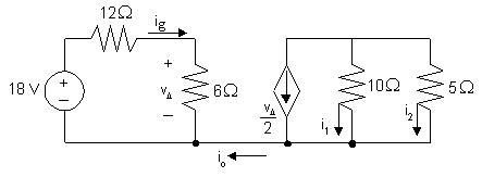
[d] p4Ω = i2 g (4)=6.25(4)=25W
p20Ω = i2 a(20)=(4)(20)=80W
p80Ω = i2 b(80)=0 25(80)=20W
[e] p50V (delivered)=50ig =125W
Check:
Pdis =25+80+20=125W
Pdel =125W
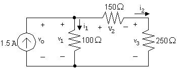
[a] WriteaKCLequationatthetopnode:
1.5+ i1 + i2 =0so i1 + i2 =1.5
WriteaKVLequationaroundtherightloop:
v1 + v2 + v3 =0
FromOhm’slaw,
v1 =100i1 ,v2 =150i2,v3 =250i2 Substituting, 100i1 +150i2 +250i2 =0so 100i1 +400i2 =0
Solvingthetwoequationsfor i1 and i2 simultaneously, i1 =1 2Aand i2 =0 3A
[b] WriteaKVLequationclockwisearoundtheleftloop:
vo + v1 =0but v1 =100i1 =100(1.2)=120V
So vo = v1 =120V
[c] Calculatepowerusing p = vi forthesourceand p = Ri2 fortheresistors:
psource = vo(1 5)= (120)(1 5)= 180W
p100Ω =1 22(100)=144W
p150Ω =0 32(150)=13 5W
p250Ω =0.32(250)=22.5W
Pdev =180W Pabs =144+13 5+22 5=180W
P2.20Labeltheunknownresistorvoltagesandcurrents:
[a] ia = 3.5 175 = 0 02A(Ohm’slaw)
i1 = ia =0.02A(KCL)
[b] vb =200i1 =200(0.02)=4V(Ohm’slaw)
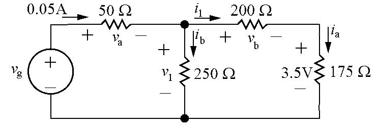
v1 + vb +3.5=0so v1 =3.5+ vb =3.5+4=7.5V(KVL)
[c] va =0.05(50)=2.5V(Ohm’slaw)
vg + va + v1 =0so vg = va + v1 =2 5+7 5=10V(KVL)
[d] pg = vg(0 05)=10(0 05)=0 5W
P2.21 [a] UseKVLfortherightlooptocalculatethevoltagedropacrossthe right-handbranch vo.Thisisalsothevoltagedropacrossthemiddle branch,soonce vo isknown,useOhm’slawtocalculate io:
vo =1000ia +4000ia +3000ia =8000ia =8000(0 002)=16V
16=2000io
io = 16 2000 = 8mA
[b] KCLatthetopnode: ig = ia + io =0.002+0.008=0.010A=10mA.
[c] Thevoltagedropacrossthesourceis v0,seenbywritingaKVLequation fortheleftloop.Thus,
pg = voig = (16)(0.01)= 0.160W= 160mW. Thusthesourcedelivers160mW.
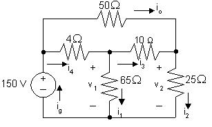
v2 = 150 50(1)=100V
i2 = v2 25 = 4A
i3 +1= i2,i3 =4 1=3A
v1 =10i3 +25i2 =10(3)+25(4)=130V
i1 = v1 65 = 130 65 = 2A
Notealsothat
i4 = i1 + i3 =2+3=5A
ig = i4 + io =5+1=6A
[b] p4Ω =52(4)=100W
p50Ω =12(50)=50W
p65Ω =22(65)=260W
p10Ω =32(10)=90W
p25Ω =42(25)=400W
[c] Pdis =100+50+260+90+400=900W
Pdev =150ig =150(6)=900W
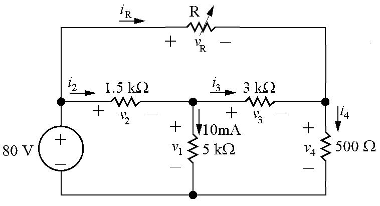
P2.23Labelallunknownresistorvoltagesandcurrents:
Ohm’slawfor500Ωresistor: i4 = v4/500=20/500=0 04=40mA
KCLforrightnode:
i3 + iR = i4 → iR = i4 i3 =0 04 0 01=0 03=30mA
KVLforouterloop:
80+ vR + v4 =0 → vR =80 v4 =80 20=60V
Therefore, R = vR iR = 60 0.03 =2000=2kΩ
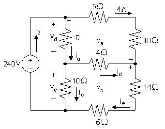
P2.24 [a]
va = (5+10)(4)=60V
240+ va + vb =0so vb =240 va =240 60=180V
ie = vb/(14+6)=180/20=9A
id = ie 4=9 4=5A
vc =4id + vb =4(5)+180=200V
ic = vc/10=200/10=20A
vd =240 vc =240 200=40V
ia = id + ic =5+20=25A
R = vd/ia =40/25=1.6Ω
[b] ig = ia +4=25+4=29A pg (supplied)=(240)(29)=6960W
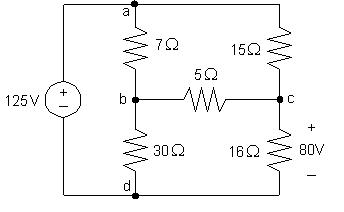
P2.25 [a]
icd =80/16=5A
vac =125 80=45so iac =45/15=3A
iac + ibc = icd so ibc =5 3=2A
vab =15iac 5ibc =15(3) 5(2)=35Vso iab =35/7=5A
ibd = iab ibc =5 2=3A
Calculatethepowerdissipatedbytheresistorsusingtheequation
pR = Ri2 R:
p7Ω =(7)(5)2 =175W p30Ω =(30)(3)2 =270W

p15Ω =(15)(3)2 =135W p16Ω =(16)(5)2 =400W
p5Ω =(5)(2)2 =20W
[b] Calculatethecurrentthroughthevoltagesource:
iad = iab iac = 5 3= 8A
Nowthatwehaveboththevoltageandthecurrentforthesource,wecan calculatethepowersuppliedbythesource:
pg =125( 8)= 1000Wthus pg (supplied)=1000W
[c] Pdis =175+270+135+400+20=1000W
Therefore, Psupp = Pdis
P2.26 [a] v2 = 100+4(15)=160V; v1 =160 (9+11+10)(2)=100V
[b] Calculatepowerusingtheformula p = Ri2:
p9Ω =(9)(2)2 =36W; p11Ω =(11)(2)2 =44W
p10Ω =(10)(2)2 =40W; p5Ω =(5)(6)2 =180W
p30Ω =(30)(3)2 =270W; p4Ω =(4)(5)2 =100W
p16Ω =(16)(5)2 =400W; p15Ω =(15)(4)2 =240W
[c] vg =190V
[d] Sumthepowerdissipatedbytheresistors:
pdiss =36+44+40+180+270+100+400+240=1310W
Thepowerassociatedwiththesourcesis
pvolt source =(100)(4)=400W
pcurr source = vg ig =(190)( 9)= 1710W
Thusthetotalpowerdissipatedis1310+400=1710Wandthetotal powerdevelopedis1710W,sothepowerbalances.
P2.27 [a]
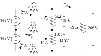
Startbycalculatingthevoltagedropsduetothecurrents i1 and i2.Then useKVLtocalculatethevoltagedropacrossand35Ωresistor,and Ohm’slawtofindthecurrentinthe35Ωresistor.Finally,KCLateach ofthemiddlethreenodesyieldsthecurrentsinthetwosourcesandthe currentinthemiddle2Ωresistor.Thesecalculationsaresummarizedin thefigurebelow:
p147(top) = (147)(28)= 4116W
p147(bottom) = (147)(21)= 3087W
Thereforethetopsourcesupplies4116Wofpowerandthebottom sourcesupplies3087Wofpower. [b]
Psup =4116+3087=7203W
Therefore, Pdis = Psup =7203W
P2.28 [a] Plotthe v i characteristic
Fromtheplot: R = ∆v ∆i = (130 50) (10 0) =8Ω
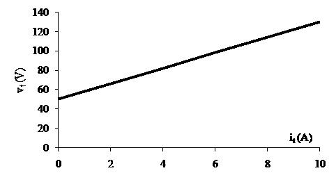
When it =0, vt =50V;thereforetheidealvoltagesourcehasavoltage of50V.

When vt = 0,it = 50 8 = 6 25A
Notethatthisresultcanalsobeobtainedbyextrapolatingthe v i characteristicto vt =0.
P2.29 [a] Plotthe v i characteristic:
Problems 2–25
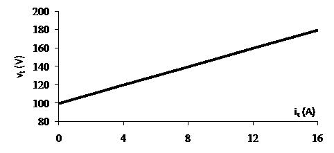
Fromtheplot:
R = ∆v ∆i = (180 100) (16 0) =5Ω
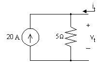
When it =0, vt =100V;thereforetheidealcurrentsourcemusthavea currentof100/5=20A
[b]
Weattacha20Ωresistortothedevicemodeldevelopedinpart(a):
WriteaKCLequationatthetopnode:
20+ it = i1
WriteaKVLequationfortherightloop,inthedirectionofthetwo currents,usingOhm’slaw:
5i1 +20it =0
Combiningthetwoequationsandsolving, 5(20+ it)+20it =0so25it = 100;thus it = 4A
Nowcalculatethepowerdissipatedbytheresistor:
p20Ω =20i2 t =20( 4)2 =320W
[b] ∆v =25V;∆i =2.5mA; R = ∆v ∆i = 10kΩ
[c] 10,000i1 =2500is ,i1 =0.25is 0.02= i1 + is =1.25is,is =16mA
[d] vs(opencircuit)=(20 × 10 3)(10 × 103 )=200V
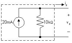
[e] Theopencircuitvoltagecanbefoundinthetableofvalues(orfromthe plot)asthevalueofthevoltage vs whenthecurrent is =0.Thus, vs(opencircuit)=140V(fromthetable)
[f] Linearmodelcannotpredictthenonlinearbehaviorofthepractical currentsource.
P2.31 [a] Beginbyconstructingaplotofvoltageversuscurrent:
[b] Sincetheplotislinearfor0 ≤ is ≤ 24mAamdsince R =∆v/∆i,wecan calculate R fromtheplottedvaluesasfollows:
R = ∆v ∆i = 24 18 0.024 0 = 6 0.024 =250Ω
Wecandeterminethevalueoftheidealvoltagesourcebyconsideringthe valueof vs when is =0.Whenthereisnocurrent,thereisnovoltage dropacrosstheresistor,soallofthevoltagedropattheoutputisdueto thevoltagesource.Thusthevalueofthevoltagesourcemustbe24V.
Themodel,validfor0 ≤ is ≤ 24mA,isshownbelow:
[c]
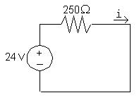
Thecircuitisshownbelow:
[d]
WriteaKVLequationintheclockwisedirection,startingbelowthe voltagesource.UseOhm’slawtoexpressthevoltagedropacrossthe resistorsintermsofthecurrent i:
24V+250i +1000i =0so1250i =24V
Thus, i = 24V 1250Ω = 19.2mA
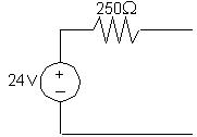
Thecircuitisshownbelow:
[e]
WriteaKVLequationintheclockwisedirection,startingbelowthe voltagesource.UseOhm’slawtoexpressthevoltagedropacrossthe resistorsintermsofthecurrent i: 24V+250i =0so250i =24V
Thus, i = 24V 250Ω = 96mA

Theshortcircuitcurrentcanbefoundinthetableofvalues(orfromthe plot)asthevalueofthecurrent is whenthevoltage vs =0.Thus, isc =48mA(fromtable)
[f]
Theplotofvoltageversuscurrentconstructedinpart(a)isnotlinear(it ispiecewiselinear,butnotlinearforallvaluesof is).Sincetheproposed circuitmodelisalinearmodel,itcannotbeusedtopredictthenonlinear behaviorexhibitedbytheplotteddata.
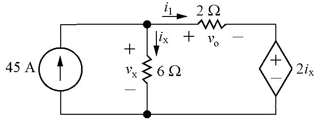
P2.32Labelunknownvoltageandcurrent:
vx + vo + 2ix =0(KVL)
vx =6ix (Ohm’slaw)
Therefore 6ix + vo +2ix =0so vo =4ix
Thus ix = vo 4 Also, i1 = vo 2 (Ohm’slaw)
45= ix + i1 (KCL)
Substitutingforthecurrents ix and i1:
45= vo 4 + vo 2 = 3vo 4
Thus vo =45 4 3 = 60V
Theonlytwocircuitelementsthatcouldsupplypowerarethetwosources,so calculatethepowerforeachsource:
vx =6ix =6 vo 4 = 6(60/4)=90V
p45V = 45vx = 45(90)= 4050W
pd s =(2ix)i1 =2(vo/4)(vo/2)=2(60/4)(60/2)=900W
Onlytheindependentvoltagesourceissupplyingpower,sothetotalpower suppliedis4050W.
P2.33Labelunknowncurrent:
1 = (4000)(0.01)=40V(Ohm’slaw)

v1 2 = 2000io +6000io =8000io (KVL)
Thus,
Calculatethepowerforallcomponents:
Thusthepowerinthecircuitbalances. P2.35 [a] io =0becausenocurrentcanexistinasingleconductorconnectingtwo partsofacircuit.
P2.36 [a]
Therefore,
vo =40iσ =80V
[b] ig =currentoutofthepositiveterminalofthe50Vsource
( 0 015625)=0; i1 =3 125mA
vg =60i1 +260i1 =320i1
Therefore, vg =1V
P2.38 iE iB iC =0
therefore
P2.39HereisEquation2.25:
Therearethreeradiators,sothetotalpowerforthisheatingsystemis
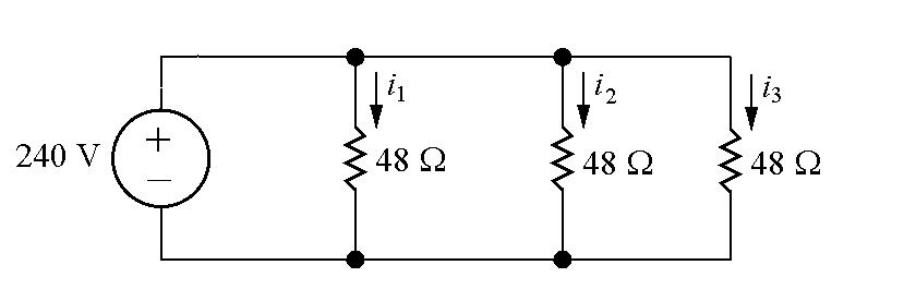
P2.42Eachradiatorismodeledasa48Ωresistor:
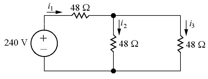
WriteaKVLequationfortheleftandrightloops: 240+48i1 =0 → i1 = 240 48 = 5A 48i1 +48i2 +48i2 =0 → i2 = i1 2 = 5 2 = 2 5A
Thepowerforthecenterradiatoris
pcen =48i2 1 =48(5)2 =1200W
Thepowerforeachoftheradiatorsontherightis
pright =48i2 2 =48(2 5)2 =300W
Thusthetotalpowerforthisheatingsystemis
ptotal = pcen +2pright =1200+2(300)=1800W
Thecenterradiatorproduces1200W,justlikethethreeradiatorsinProblem 2.41.Buttheothertworadiatorsproduceonly300Weach,whichis1/4thof thepoweroftheradiatorsinProblem2.41.Thetotalpowerofthis configurationis1/2ofthetotalpowerinFig.2.41.
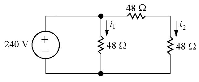
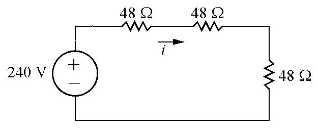
P2.43Eachradiatorismodeledasa48Ωresistor:
WriteaKVLequationfortheleftandrightloops: 240+48i1 +48i2 =0
Calculatethepowerforeachradiatorusingthecurrentforeachradiator:
Thusthetotalpowerforthisheatingsystemis
Allradiatorsinthisconfigurationhavemuchlesspowerthantheir counterpartsinFig.2.41.Thetotalpowerforthisconfigurationisonly22 2% ofthetotalpowerfortheheatingsysteminFig.2.41.
P2.44Eachradiatorismodeledasa48Ωresistor:
WriteaKVLequationforthisloop:
Calculatethepowerforeachradiator:
Calculatethetotalpowerforthisheatingsystem:
EachradiatorhasmuchlesspowerthantheradiatorsinFig.2.41,andthe totalpowerofthisconfigurationisjust1/9thofthetotalpowerinFig.2.41.