
NON CYCLONICN2 & N3
ITI SPEC FRAME R LVL E11.7

SPECFRAME 11.7

ISSUE 2.0 - OCTOBER 2023
SPECIFICATION GUIDE

NON CYCLONICN2 & N3
ITI SPEC FRAME R LVL E11.7
SPECFRAME 11.7

Since establishment in 1987 in Five Dock, NSW, Independent Timber Importers has been on a mission to redefine the timber industry wholesale/distribution landscape. ITI has worked closely with industry suppliers, customers and associations to promote the strength, beauty and environmental benefits of using timber. At the same time ITI redefined the role of the wholesaler with its distribution and service models. With its large investments in distribution centres, product development, people and service standards; in early 2002 ITI dropped the name Independent Timber Importers and replaced this with ITI and introducing the new logo with the “Innovative Timber Ideas” phrase which more accurately describes the attitude of the company.
Today ITI consists of 9 distribution sites across Australia with over 130,000m2 of undercover storage, a state of the art re-manufacturing, treating and priming plant in Chile, an office in Indonesia, 3 distribution locations in New Zealand and growing sales in the USA.
True to its name, the success of ITI lies in its commitment to innovation in both service and product development. This commitment has led to premier brands such as Design Pine, EziTrim Plus, Spec LVL products along with the distribution of market leading products such as Pacific Woodtech, Metsa Wood, Weathertex and Modwood. ITI has also led the way with service standards winning countless industry awards for its service.
ITI source Engineered Wood Products from leading manufacturers to ensure the needs of building designers through to the end users are met with the best available product.
ITI Engineered Wood Products offering is comprised of 3 major products with each intended on complimenting the next. Laminated Veneer Lumber (LVL), I-Joists and Glue Laminated Timber Beams (GL). These products along with innovated construction details and dedicated support staff form an innovative platform which set ITI Engineered Wood Products apart from the rest.

Available from ITI Australia is ITI Design Spec. A single member design software developed to assist industry professional with the specification of ITI’s vast range of structural timber products. Free licences are available to suit builders, timber merchants, frame & truss professionals and engineers. Head to www.itiaustralia.com.au to download for free.
ITI Spec Frame® E11.7 is a versatile laminated veneer lumber product which is ideal for general residential timber framing such as rafters, under-purlins, struts, lintels, rafters and sub-floor joists.
The E11.7 grade is positioned noticeably above MGP10 but has all the benefits of being and engineered timber product; such as being available in lengths up to 12.0m long which allows for wider continuous spans. It’s light weight and easy to use.
ITI Spec Frame® R is made from 3mm rotary peeled from radiata pine logs which are ultrasonically graded and laid up, glued and pressed together using an marine grade, A-Bond type, adhesive. An inspect repellent is added to the glue line to prevent attack for termites and borer insects south of the Tropic of Capricorn.
Raw wood material comes from FSC-certified forests ensuring that the origin of the raw material is sustainably managed and traceable to its origins.
Over 70 unique types of quality control data points are recorded throughout the production process along with an independent 3rd party quality assurance program undertaken by NATA accredited testing laboratories. All ITI Spec LVL products are supported by the JAS-ANZ recognized Bureau Veritas S-Mark product certification program.
It is a requirement of the Australian standard for manufacturing Laminated Veneer Lumber that an external A bond be achieved between the veneers by using a phenolic type adhesive.


150mm
NAIL LAMINATION NOTES:
1. Minimum 2 Rows for Depths up to 305mm
2. Minimum 3 Rows for Depths up to 450mm
Nail Lamination - 2-Ply & 3-Ply Members
Minimum Nail Sizes
45mm Members - 2.80x75mm
3. Drive opposing nail pattern to opposite side of member
4. Nails to penetrate second member by at least 50%
5. First nails to be located approx. 135mm from the edge
6. Additional nails added under point loads and over supports
7. Repeat nailing to nailing pattern to each lamination
2 Ply Lamination requires
2 Row of Bolts
600mm
BOLT LAMINATION NOTES:
3 Ply Lamination requires
3 Row of Bolts
600mm
1. M12 (8.8/S) bolts with 55mm washers at 600mm centres staggered in 2 rows for 2 ply beams
2. M12 (8.8/S) bolts with 55mm washers at 600mm centres staggered in 3 rows for 3 ply beams
3. Minimum 60mm edge clearance required
4. Ensure pre-camber of Glue Laminated Beams is set in the upward direction
5. Apply an additional 2, or 3 M12 bolts directly under any point points
6. Bolt members together prior to applying loads
D/2 max.
D/2 max.
D/3 max.
D/8 or 25mm max.
6 x B min. B/4 max. D
D/8 max. D min. D/8 max. No min.
D
D/2 or 100mm max. D/6 min.
Notes:
1. No more than 2 holes are permitted within an 1800mm length
2. For more information refer to Section 4.1.6 of AS 1684.
Single Span Continuous Span
A continuous span only applies when the smaller of the spans is no less than half the larger span. Where this does not apply; both spans are to be treated as singles spans or further design analysis is required. Measure spans between internal faces of the supports.
(a) Block skew nailed to beam and support with 3/75mm framing nails to each member
(b) Minimum 35x32mm tie nailed to the top of the beam and to the support with 2/75mm framing nails at each end
(c) G.I. Strap looped over beam with 2/30x2.8mm nails at either end and into the beam
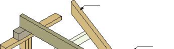
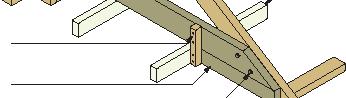
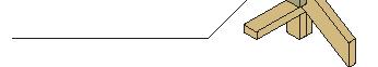
Rafter / Taper Cut to Counter, Hanging and Strutting Beams
17.5o Minimum cut angle
The greater of ‘D’/3 or 100mm ‘D’
Roof beam ends may be taper cut to avoid interference with roof coverings. It may be necessary to cantilever roof battens and butt into the side of these members. This detail may be used for Counter, Hanging, Strutting Beams as well as combination Strutting / Counter and Strutting / Hanging Beams.
Ridge Beam / Board
Rafter
Underpurlin
Strutting Beam
Ceiling Joist
Roof Strut
Rafters are members positioned parallel to each other designed to support, and fix, the roof covering. Rafters may also be designed to support the ceiling for cathedral type roofs.
Considerations for rafter centres should include; performance of the rafter, the span of roof battens and the plasterboard or ceiling joists.
Rafters are to be fixed and tied-down at all supports to accommodate any uplift generated by wind loads. Rafters are to be supplied in a single length or joined over a support.
Birdsmouth
Rafter Support Types
Wedge or Tapered Plate
‘D’
‘D’/3 Max.
Maximum allowable birds-mouth to be no greater than 1/3 the rafter depth
Wedge or Tapered Plate
Edges to be fixed down to the support without any splitting. Tie-down the rafters directly to supports
Simpson Strong-Tie VPA Connector
VPA25 - Supporting 45mm Spec Beam Rafter Fixings
Max. Loads Uplift Dead
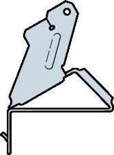
To Support
8x 75x3.75 Nails 1.58 kN 2.88 kN
To Supported Member 2x 40x3.75 Nails
Simpson Strong-Tie VPA connector with additional tie-down to rafters as required. 1.58 kN
maximum tie-down supplied by VPA connector.
Capacities shown apply to the VPA being fixed to a plate with a minimum joint group of JD4 using all connections as indicated in the table above.
Installation of VPA Connectors
1: Install top and face 3.75x75
Step 2: Seat rafter with a hammer, adjusting the “B” flange to the required pitch
Rafter
Roof Beam
Ceiling Joist
Underpurlin
Roof Strut
Strutting Beam
UnderpurlinSpan
Underpulins are compact, lightweight intermediate roof members used to support rafters while being concealed in the roof cavity. Underpurlins bear down onto Strutting Beams or other supports via Roof Struts. Underpurlin’s span tables accommodate loads from the rafters and roof covering only. No ceiling loads are accounted for.
Roof Struts are used to provide support to roof members, such as Roof Struts include Underpurlins, Hip Rafters and Ridge Boards and transfer loads to Walls, Strutting Beams, Strutting / Hanging Beams and Strutting / Counter Beams.
Roof Struts may be installed perpendicular to the overlying Rafters, perpendicular to the support or as Fan / Flying Struts. Refer to Australian Standard AS1684 for more information.
Roof Struts - Vertical
Rafter
Underpurlin
Roof Strut
Strutting Beam
Roof Struts - Perpendicular to Rafters (Max 350 Pitch)
Rafter
Underpurlin
Roof Strut
Block
Strutting Beam
Notes:
1. Roof Strut designs governed by AS1720.3 Table 4, Table 3.2.2.3, Load Case 4 (1.2D + Wind Down)
2. For comparison value against Load Case 1 (1.35D) multiple the above values by 2.72
Ridge Beam
Rafter
Intermediate Roof Beam
Roof Beams are members designed to support Rafters. Rafters may be supported by butting into the face of Roof Beams or supported over Roof Beams. Roof Beams can be designed to transfer either just roof or roof and ceiling loads supported by the rafters.
Care should be taken to ensure the correct supports are applied to each Roof Beam support and that sufficient tie-down has been applied. Refer to Australian Standard AS1684 for more information.
Ceiling Joists are members which support the ceiling lining only. Ceiling Joists spacing shall be governed by the maximum allowable span of the supported ceiling lining.
Ceiling Joists may free span between internal supports or be supported intermediately by Hanging Beams. Ceiling Joists are to be fixed to Hanging Beams via either 35x32mm timber cleats / droppers with 2/ 75x3.15 framing nails to each member, 25x1.6mm galvanized strap, ceiling joist hangers or Simpson Strong-Tie TCP clips.
Hanging Beams are designed to support loads transferred via the ceiling joists only. Hanging Beams are generally positioned perpendicular to the Ceiling Joists which are then hung from the underside of the member.
Where Hanging Beams are supported by external walls which also support Rafters; provisions are required to the end of the member to prevent extrusion through the roof covering. A premanufactured Splayed Beam or Jack Trimmer Joist will be required.
Timber Cleat fixed to with 2/75x3.15 Nails to both Hanging Beam and Block
Block the same depth as Ceiling Joists and same width as Hanging Beam
2x M10 Bolts through Hanging Beam and paired rafter
Counter Beams run parallel to ceiling joists and are designed to support Hanging Beams. The supported Hanging Beam will be supporting underlying ceiling joists. The spans published for Counter Beams have been determined by supporting the Hanging Beam in the worst case scenario.
Determining Ceiling Area supported by Counter Beam
Support to Counter Beam
Counter Beam Hanging Beams supporting Ceiling Joists
Ceiling Joists
Support to Counter Beam Supported Ceiling Area
Roof Battens are members which span over and across rafters. They are designed to support the roof covering only. Roof Battens are installed on the flat and are to span across a minimum of 3 rafters.
Roof Batten Cantilever to be the lesser of the Cantilever Span shown above or half the actual roof Batten Span used onsite.
1. Refer to page 3 of this guide to check product availability in your area
2. Refer to page 4 of this guide for span and span type definitions
3. All members to be installed per AS1684.2 and good building practice
4. Member sizes specified are based on serviceability criteria outlined in AS170.3
5. Beam details shown are based on the Floor Joist or Rafter being supported continuously over
6. Where members are supporting roof loads a maximum roof pitch of 35 degrees has been accounted for in calculations
7. Rafter and Ceiling joist spacings / centres should be selected as such to obtain adequate support for Roof sheeting or Ceiling Material respectively. Refer to product manufacturer for details
8. Always confirm the required roof batten centres against the roofing manufacturers recommendations
9. Roof Batten Cantilever to be the lesser of the value shown above and the Roof Batten Span
10. Member sizes nominated are based on the product being fully protected from moisture and maintains an average moisture content of 15%, or less, over a period of 12 months i.e. K4 = 1.0 per AS1720.1 clause 2.4.2.3.
11. Member sizes nominated are based on construction in coastal areas south of latitude 250 and south of latitude 160 in all other areas i.e. k6 = 1.0 per AS1720.1 clause 2.4.3
Minimum Bearing Length Requirements
* Minimum 70mm Bearing Length
# Minimum 90mm Bearing Length
** Minimum 120mm Bearing Length
ITI Spec LVL products – like all other engineered wood products – must be handled and stored properly and carefully. Incorrect handling and storage may introduce defects on product’s surfaces, edges or corners. Furthermore, the dimensional stability of the product may suffer.
While transporting or storing the product, increased moisture caused by rain or splashing must be avoided. If ITI Spec LVL products products are moved with a forklift truck, wide enough forks must be used in order to avoid damaging the product. When lifting several packs at a time, the distance between forks must be wide enough to ensure safe lifting. Surface-treated products should be delivered direct to site without additional, unnecessary off-loading during delivery.
ITI Spec LVL products must be stored under cover. When storing the products temporarily on site, a solid, straight and dry platform should be used. The height of ground bearers must be at least 300 mm. To avoid twisting of the product, the bearers between packs must be aligned vertically with the ground bearing timbers.
The plastic wrapping of each pack must be cut open from underneath to enable moisture to evaporate from the bundles. If the products are stored on site for longer than one week, the bundles must be covered with an additional protective covering. Conditions of the products and protective cover must be monitored regularly during storage.
ITI Spec LVL product packs may be unloaded on site with either a forklift or a crane. Approved webbing slings must be used if unloading with crane. It is forbidden to use chains or wires. If unloading is done manually, the pack is opened and the products are carried one-by-one. While cutting the banding, beware of band’s ends. ITI Spec LVL products should not be dragged or dropped.
ITI Spec LVL is a light-weight material and is easy to shape, which means notable time and cost savings in construction. ITI Spec LVL products can be processed with conventional wood working and power tools. There is no need for separate specialist tools.
ITI Australia has a reputation of providing customers with a diverse range of products. By stocking a wide range of structural, outdoor and decorative building products ITI can add value without overheads to our loyal customer base. Some other products on offer include the following.
ITI Spec Chord LVL is a traditionally sized, high grade E16 product developed to give specifiers and builders peace of mind. Spec Chord LVL has been specifically developed to be used as high performance components in the manufacture of timber roof trusses. Spec Chord LVL can be found as an approved product in all propriety roof truss manufacturing software.

Design Pine is a range of exterior structural and decorative timber products coated with a genuine primer. Impregnated with a preservative to prevent the onset of decay and resist insect attack in all above ground applications, Design Pine is finger jointed and / or laminated for increased dimensional stability to give a reliable product for years to come. Don’t be fooled by blue imitations, ask for Design Pine by name.

EziTrimPlus is a range of elite primed internal mouldings manufactured from sustainable plantation grown Radiata Pine. The Radiata Pine has been milled, kiln dried and docked to remove all knots and visible imperfections. This is then finger-jointed to produce a product which has no defects whilst also having the superior finish that you have come to expect from the EziTrim Brand.

ProLam is a range of finger jointed and laminated merbau products for use in external structural and decorative applications. ProLam merbau offers a dimensionally stable and high strength building product which has been developed specifically for the outdoors. ProLam is beautiful, durable and strong.

Need exterior grade performance from a sustainable source?
Experience the Extreme Timber range. Extreme Timber provides you with the products which have been missing from the traditional outdoor softwood range. The range includes Extreme Post and Extreme Beam. Extreme Post is a pine post with hazard class 4 treatment making it capable of being installed directly into the ground. Extreme Beam is glue laminated GL8 grade beams in the same widths as traditional treated pine. Extreme beam offers additional flexibility for treated pine outdoor structure design.
The worlds first treated pine product that exceeds BAL-40 requirements as set out in the Australian Standard AS3959-2018. Currently available in 45mm structural MGP10, decking and screening, FLAMEfixx dFx® products also offer protection against fungal decay and insect (termite) attack to hazard level 3 (H3).
ITI LOCATIONS:
ITI Technical Support Centre
68-80 Kirkham Road West, Keysborough, Victoria 3173
E || ewp@iti.net.au
P || 03 9392 8400
ITI Queensland (Brisbane)
63 Creek Street, Bundamba, Queensland 4034
P || 07 3436 8400
E || ewpqld@iti.net.au
ITI New South Wales (Sydney) 59 Dunheved Circuit, St Marys, New South Wales 2760
P || 02 8805 5000
E || ewpnsw@iti.net.au
ITI South Australia (Adelaide) 82-94 Grand Trunkway, Gillman, South Australia 5013
P || 08 8447 0400
E || ewpsa@iti.net.au
John Cook & Sons (Sydney)
116 Links Road, St Marys, New South Wales 2760
P || 02 9833 0355
E || ewp@johncook.net.au
ITI Victoria (Melbourne) 68-80 Kirkham Road West, Keysborough, Victoria 3173
E || ewpvic@iti.net.au
P || 03 9394 8400
ITI Queensland (Townsville) 46-50 Perkins Street West Railway Estate
P || 07 4724 5509
E || ewpqld@iti.net.au
ITI New South Wales (Newcastle) 19 Nelson Road, Cardiff, New South Wales 2285
P || 02 4953 7666
E || ewpnsw@iti.net.au
ITI Western Australia (Perth) 102-108 Bannister Road, Canning Vale, Western Australia 6155
P || 08 9256 5700
E || ewpwa@iti.net.au