International Research Journal of Engineering and Technology (IRJET) e-ISSN:2395-0056

Volume: 09 Issue: 09 | Sep 2022 www.irjet.net p-ISSN:2395-0072
International Research Journal of Engineering and Technology (IRJET) e-ISSN:2395-0056
Volume: 09 Issue: 09 | Sep 2022 www.irjet.net p-ISSN:2395-0072
Arunendra Nath Tripathi1, Raj Kumar
1Research Scholar, Department of Physics & Electronics, Dr. Rammanohar Lohiya Avadh University, Ayodhya. 2 Professor, Department of Physics & Electronics, Dr. Rammanohar Lohia Avadh University, Ayodhya. ***
Abstract- In this paper, survey has been done on low pass filter used in biomedical devices having low power consumption, low weight and good linearity. Different types of low pass filters with their respective technologies have been described in this paper. It is found that low pass filter with low noise low power consumption and low weight is necessary part of portable biomedical instrument. Our future work will be based on the implementation of RKTG pair in low pass filter circuits by changing aspect ratio of MOSFETsat45nm,90nmand180nmtechnologies
Key words- Low pass filter, Biomedical devices, RKTG pair, CMOS,Lowpower
1. Introduction:-
Theshrinkingfeaturesizehasalways attractedthecircuit designers to look forwards to the overlapping future of semiconductor technology [1] Continuous Technology feature size scaling has enabled denser and faster digital circuitreducessuccessivelywiththesupplyvoltage,which hasbeendriventhedigitalindustrytomoveforwardslow supply voltage [2] In the recent years due to growing marketoftheportableandwearablebiomedicaldevicesto low voltage and low power supply need archiving a long battery life and light weight of the devices [3].The necessary requirement in portable biomedical devices for achieving the low cut-off frequency at the same time of lowpowerconsumptionsandlowarea [4] LPFswithvery low cut-off frequencies are heart of biomedical signal processing[4]-[5]. Modification of already existing technology to achieve the needed target of low voltage operation means saving in cast as well as resecures [6]. Digital and Analog circuit coexist of SOC circuit, power consumedbydigitalcircuitisrequiredquadraticallywitha low voltage and capture this advantage are forced to design Analog circuit operating at low supply [7]. MOSFETs provided better option for above requirement becauseMOSFETare usuallybiased in the weak inversion as they must conducted current in the ranged of few nanoampere [8]. A feasible solution for designing low power circuit is to operate MOS devices in SUB-Threshold
region [9]. Metal oxide semiconductor (MOS ) devices biased in the sub-threshold region are exploited to maximize power efficiency and achieve very low power consumption, and a switched resistor approach is used to keepthesiliconarea[10]
Mostly systems mentioned above have pre-processing blocks such as low noise preamplifier and filters for the possession of low frequency signals are employed [31]. These blocks should not have any type of distortion that can explode the necessary signal. To meet these requirements, the pre-processing blocks must have presenthighperformanceoverthegainandfrequencyfor low frequency signal processing. To achieve the required parametersforsignalprocessing,differenttopology-based filters like: Switched-Capacitor Based Topology for Voice BandApplications,gm-cFilters,FeedbackandCancellation topology has been designed. But these offers some disadvantages like clock feed-through, aliasing problem, temperature dependent etc. To avoid the above problems, wehavedesignedahighfrequencyrangeatlowfrequency second order active low pass filter using complementary compound pair [32]-[40]. It provides very high current gain in case of BJT (Bipolar Junction Transistor) and very high voltage gain in case of MOS (Metal Oxide Semiconductor) to avoid the dependency of temperature and provide low frequency signal amplifications with low power consumption. It is a monolithic filter for IC fabrication.
2.1. Low Pass Filter- If an ideal low pass filter existed, it wouldcompletelyblockoreliminatesignalsabovethecutoff frequency, and perfectly pass signal below the cut-off frequency.inanidealfiltervarioustradesoffsaremadeto gate optimum performance for given application[10] The design of very low frequency filter (10Hz) is not straight forward especially for integrated circuit implementations where chip realization of larger time constant are needed [4].Low pass filter with very cut-off frequencies are key blocks in biomedical devices[11].[12] Filter are networks
International Research Journal of Engineering and Technology (IRJET) e-ISSN:2395-0056
Volume: 09 Issue: 09 | Sep 2022 www.irjet.net p-ISSN:2395-0072
thatpreparessmallsignalsinafrequencydependantway, Filtercanbemakingusetoseparatesignal,passingtheone ofintriguedandputbyternstheunwantedfrequencies.In the design of analog filters the number of active devices used are reduces because of the concerns like power consumptions and noise distribution[13].Integrated LPF are basic building blocks for analog signals processing whiletheyaretypicallyimplementedusingeitheranactive RC or a gm c architecture. The performance of such filters depends on the OTA (operational transconductance amplifier)[14]. Operational Transconductance Amplifier is usedforlowpoweranalogfilteringapplication,becauseof its linear input-output characteristics. IN analog circuit applicationOTAisfundamentalblock.ThefunctionofOTA issameasOP-AMPbecausebothcontaindifferentialinput buttheyarevaryasinOTAwheretheoutputisdifference incurrentbutinOP-AMPisinvoltage.[15]
2 2. Types of Filter Circuits-Fourtypesoflowpassfilter wereexaminedduringthedesignphaseofthecircuit
Butterworthtype Chebyshev,Itype ChebyshevIItype Ellipticaltype
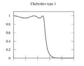
2.2.1. Butterworth filters: Butterworth filters in 1930 it was first designed by British engineer and Physicist Stephen Butterworth in his paper entitled “On the theory of filter Amplifiers”. Butterworth filter is a type of filter designed to have a frequency response that is as possible in pass band. Butterworth filters stays maximally flat in passbandwiththeexpansesmuchslowerrealofatcut-off frequencyasshowninfig.1
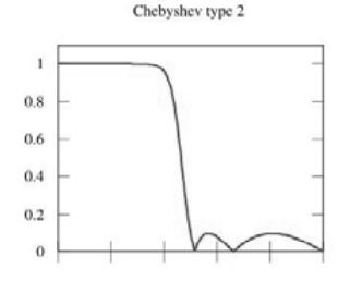
2.2.2. Chebyshev I: Chebyshev filters are mostly used to separate one band frequencies from another. Chebyshev filtertypeIhaveequal rippleinpassbandandmonotonic in stopband but its rolls off very fast but at expense of grater pass band ripple i.e. It has ripples in pass band but itsrollsoffveryfastasshowninfig.2
Fig.2-ChebyshevItypefilterfrequencycurve
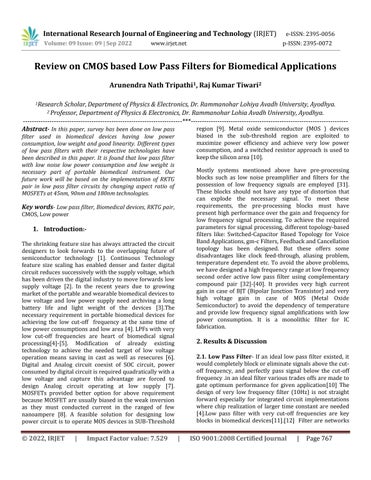
2.2.3. Chebyshev II: ChebyshevIItypesfilterismaximally flat in the passband and has an equal amplitude ripple in stopband.IntheChebyshevIIfilterspecifythefrequencies at which the stopband begins and the maximum ripple amplitude.ChebyshevIItypesfilterhasinripplestopband has the same roll off as type I and has no ripple in pass band as shown in below figure i.e.It has ripple stop band has the same roll off as type I and has no ripple in pass bandasshowninbelowfigure3
Fig.1-Butterworthfrequencycurve
Fig.3-frequencyresponsecurveChebyshevTypeIIfilter
International Research Journal of Engineering and Technology (IRJET) e-ISSN:2395-0056
Volume: 09 Issue: 09 | Sep 2022 www.irjet.net p-ISSN:2395-0072
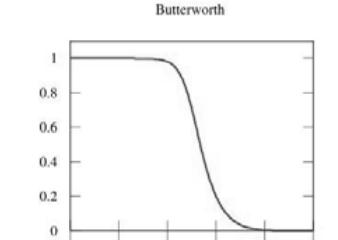
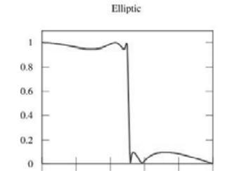
2.2.4. Elliptic filter: TheellipticfiltersmixbyChebyshevI andChebyshevIIithasripplesinbothstopbandandpass band but has the steepest roll off at cut- off frequency as showninfig.4.Theellipticfiltercanachieveasharpercut off than the Chebyshev but has a reduced stopband performance.ThisfiltertypeisbestusedwherethePAhas toworkoverawidefrequencyrangeandthereforethereis a requirement for a filter that cuts off sharply above the maximum operating frequency to give good rejection of the harmonics of the minimum operating frequency. The otherapplicationwhereanellipticfiltermaybesuitableis asasimplefiltertoreducethesecondandthirdharmonics of a PA stage that already has a fair degree of harmonic filteringproducedbyahigh Q outputmatchingcircuit.The design method is similar to that of the Chebyshev being basedonstandardcurvesandtablesofnormalizedvalues.
Fig.4-frequencyresponsecurvebyellipticfilter
2.3. Comparison table of low pass filter in use of biomedical devices – Table 1 summarizes the different work done on low pass filters with their respective parameters.
Year Reference Types of filers Technology Order Power supply Band width Power consumption Dynamic rang Active area
2000 [4] Elliptical 0.18 6th 1.5v 2.4Hz 10 >60dB 1mm2
2005 [17] Mixmode 0.35 - 3-4v 175Hz 0.3mv -2006 [18] SC 0.35 1.5v 15Hz 90.6nW -3dB2009 [19] ChebyshevI 0.5 3rd 5v 1.75Hz 30mW -70dB 1.5mm2
2010 [20] ChebyshevII 0.18 6th 1.8v 95Hz - 30dB2012 [21] - 65 - 1.2v 15Hz - 37dB 0.01
2012 [1] Butterworth 0.18 4th 0.5v 1.7Hz 36 -
2012 [22] Butterworth 0.25 5th 0.8v 17Hz 26 53.5dB2013 [23] - 0.18 1.8v 88Hz 594 0.042
2014 [24] Differential 0.13 5th 47.7Hz 125 44.7dB
2014 [5] Realpols 65 7th 1.2v 142Hz >100dB 0.42
2015 [6] Butterworth 180 2nd 0.5v 100Hz 225 70dB
2016 [14] Chebyshev 0.18 4th 37Hz 30.8dB 0.1mm2
2017 [25] Butterworth 90 4th 0.6v 98Hz 2 51dB
2020 [12] Chebyshev 0.35 4th 1.5v 7Hz 5.2 13
2020 [3] Chebyshev 90 2nd 0.35v 58Hz 13.46
2020 [13] Chebyshev 90 4th 0.2v 90Hz -53.7dB
2021 [26] Papoulis 22 10 1v 72Hz 0.35 0.1816mm2
2022 [34] Chebyshev 0.18 5th 0.5v 250Hz 50-60nw 57.6-60.4dB 0.036mm2
International Research Journal of Engineering and Technology (IRJET) e-ISSN:2395-0056
Volume: 09 Issue: 09 | Sep 2022 www.irjet.net p-ISSN:2395-0072
Intheliteraturesurvey,itisclearthatlowpassfilterwith low noise low power consumption and low weight is necessary part of portable biomedical instrument. CMOS low pass filter gm-c based provided better opportunity to researchertoworkonit.
Our future work will be based on the implementation of RKTG pair (Complementary compound pair) in low pass filter circuits by changing aspect ratio of MOSFETs at 45nm, 90nm and 180nm technologies This pair is combination of two CMOS inverter connected in the form of darlington pair and behave as a complementary compound pair. This RKTG pair (Complementary Compound Pair) has become a popular pair for different applications like delay system, amplifier designing, filter designing, etc. due to wide band frequency, low power consumption, low output noise, large current /voltage gain.
[1] Harishchandra, Vasantha Moodabettu and Tonse Laxminidhi. “0.5 V, 3 6µW Gm-C Butterworth low passfilterin0.18µmCMOS process.” 2012 4th Asia Symposium on Quality Electronic Design (ASQED) (2012):82-85.
[2] S. S. Rajput and S. S. Jamuar, “Low Voltage Analog Circuit Design Techniques,” IEEE Circuits and Systems Magazine, Vol. 2, No. 1, 2002, pp. 24-42. doi:10.1109/MCAS.2002.999703
[3] G.K. Soni,“Biomedical ECG /EEGApplication,” no. Icisc,pp.558–561,2020.
[4] S. Solís-bustos, J. Silva-martínez, S. Member, and F. Maloberti, “Low-Pass Filter for Medical Applications,”vol.47,no.12,pp.1391–1398,2000.
[5] P.I.I.R.L.Filter,M.Tohidian,S.Member,I.Madadi, S. Member, and R. B. Staszewski, “Analysis and Design of a High-Order Discrete-Time,” vol. 49, no. 11,pp.2575–2587,2014.
[6] S. Naik, S. Bale, T. R. Dessai, G. Kamat, and M. H. Vasantha,“CMOSprocess,”pp.590–593,2015.
[7] G. Scotti, P. Tommasino, F. Centurelli, A. Fava, P. Monsurr,andA.Tri,“HeliyonLowpowerswitchedresistor band-pass fi lter for neural recording channelsin130nmCMOS,” vol.6,no.May,pp.4–9, 2020,doi:10.1016/j.heliyon.2020.e04723.
[8] C. Sawigun and S. Thanapitak, “A 0.9-nW, 101-Hz, and 46.3-μVrms IRN Low-Pass Filter for ECG Acquisition Using FVF Biquads,” IEEE Trans. Very Large Scale Integr. Syst.,vol.PP,pp.1–9,2018, doi:10.1109/TVLSI.2018.2863706.
[9] J. R. M. K, S. Polineni, and T. Laxminidhi, “91dB Dynamic Range 9 . 5 nW Low Pass Filter for BioMedical Applications,” 2018 IEEE Comput. Soc. Annu. Symp. VLSI, no. 1, pp. 453–457, 2018, doi: 10.1109/ISVLSI.2018.00088.
[10] J. Karki, “Active Low-Pass Filter Design,” no. September,pp.1–24,2002.
[11] M. T. Sanz, “A 1V-1 . 75 P W Gm-C Low Pass Filter forBio-sensingApplications,”no.May2019,pp.1–5,2018,doi:10.1109/LASCAS.2018.8399960.
[12] B.A.Vincent,R.Krishnamoorthy,A.Devi,C.Donald, C. Bharatiraja, and M. S. Kamalesh, “Materials Today : Proceedings A self compensated low pass gain circuit for biomedical applications,” Mater. Today Proc., no. xxxx, 2020, doi: 10.1016/j.matpr.2020.10.692.
[13] P. G. Scholar, “A Design of Cmos based 4 th Order Low Pass Biquad Filter for Biomedical Applications,”vol.1,pp.1152–1155.
[14] Y. Xu, S. Leuenberger, P. K. Venkatachala, and U. Moon,“SourceFollowerBasedBiquadsin0.18µm CMOS,”pp.9–10,2016.
[15] C. Engineering and C. Engineering, “Design of TelescopicOTAbased6thorderButter-worthLow Pass Filter using 0 . 18μm CMOS Technology,” pp. 18–19,2020.
[16] A. Timár and M. Rencz, “Design issues of a low frequency low-pass filter for medical applications usingCMOStechnology,”pp.1–4,2007.
[17] M. Shojaei-baghini, R. K. Lal, and D. K. Sharma, “A Low-Power and Compact Analog CMOS Processing Chip for Portable ECG Recorders,” pp. 473–476, 2005.
[18] C. Hsu, M. Ho, Y. Wu, and T. Chen, “Design of LowFrequency Low-Pass Filters for Biomedical Applications,”vol.00,pp.690–695,2006
[19] L.Acosta,M.Jiménez,R.G.Carvajal,S.Member,A.J. Lopez-martin, and J. Ramírez-angulo, “Highly
© 2022, IRJET | Impact Factor value: 7.529 | ISO 9001:2008 Certified Journal | Page770
International Research Journal of Engineering and Technology (IRJET) e-ISSN:2395-0056
Volume: 09 Issue: 09 | Sep 2022 www.irjet.net p-ISSN:2395-0072
Linear Tunable CMOS Gm - C Low-Pass Filter,” vol.56,no.10,pp.2145–2158,2009.
[20] I. Applications, H. Shin, Y. Kim, and S. Member, “A CMOS Active- RC Low-Pass Filter With SimultaneouslyTunableHigh-andLow-Cutoff,”vol. 57,no.2,pp.85–89,2010.
[21] F. Houfaf, M. Egot, A. Kaiser, A. Cathelin, and B. Nauta, “Time Low-pass Filter for High-Data-Rate,” no.7,pp.132–133,2012.
[22] S. A. Mahmoud, A. Bamakhramah, and S. A. Altunaiji, “Digitally Programmable OTA-C Low Pass Filter for ECG Detection Systems,” no. Ic, pp. 350–353,2012.
[23] S.Lee,J.Hong,C.Hsieh,M. Liang,J.Kung,andA.A. C. Rf, “A Low-Power 13 . 56 MHz RF Front-End CircuitforImplantableBiomedical Devices,”pp.5–14,2012.
[24] K. Wang, C. Chang, and M. Onabajo, “A FullyDifferential CMOS Low-Pass Notch Filter for Biosignal Measurement Devices with High InterferenceRejection,”pp.1041–1044,2014.
[25] M. B. Elamien and S. A. Mahmoud, “Analysis and design of a highly linear CMOS OTA for portable biomedical applications in 90 nm CMOS,” Microelectronics J., vol. 70, no. September, pp. 72–80,2017,doi:10.1016/j.mejo.2017.10.009.
[26] D. Cracan, “Filter in 22nm CMOS FDSOI,” no. 1, pp. 5–9,2021.
[27] W.M.C.SansenandP.M.VanPeteghem,“Anareaefficient approach to the design of very-large time constants in switched-capacitor integrators,” IEEE, Solid-State Circuits, Vol. SSC-19, No. 5, pp. 772–780,Oct.1984.
[28] Haidong Liu, Xiaohong Peng and Wuchen Wu, “Designofa Gm-CLow Pass Filter withLowCutoff frequency,” IEEE Microelectronics & Electronics , pp.125-128,January2009.
[29] Andras Timar and Marta Rencz , “Design issues of a low frequency low pass filter for medical applicationsusingCMOStechnology”.
[30] PreetiR.LawhaleandProf.SomuluG,“CMOSBased Low Pass Filter for Biomedical Applications,” International Journal of Engineering Research and Applications(IJERA),ISSN:2248-9622,April2014.
[31] Raj Kumar Tiwari and Gaya Prasad, “A New Circuit Model Of Low Voltage High Gain CMOS Compound Pair Amplifier” Published in International Journal of Electronics and Communication Engineering & Technology (IJECET), ISSN 0976 –6464(Print), ISSN0976–6472(Online),Volume5,Issue4,April (2014), pp. 65-71 © IAEME, Journal Impact Factor (2014):7.2836(CalculatedbyGISI).
[32] Raj Kumar Tiwari, Gaya Prasad, “CMOS Compound Pair Wide Band Bio-Amplifier” Published in InternationalJournalofComputationalEngineering Research(IJCER),Vol.04,Issue6,June2014,pp.5762 ISSN (e): 2250-3005. Impact Factor: 1.145, (ComputedbyAfricanQualityCentreforJournals).
[33] Gaya Prasad, Raj Kumar Tiwari, Shiksha Jai n and Ganga Ram Mishra, “Simulation Study of CMOS CompoundPairAmplifier,”InternationalJournalof Advance Research in Science and Engineering, Volume No. 07, Special Issue No. 01, April 2018, Impact Factor (2018): 2.83. ISSN No.(o) 23198354,(P)2319-8346.
[34] PreetiR.Lawhale,Prof.SomuluG,“CMOSBasedLow Pass Filter for Biomedical Applications”, Research Article, International Journal of Engineering Research and Applications (IJERA,) ISSN: 22489622,2014.
[35] PreetiR.Lawhale,MayuriM.Soni,“DesignofCMOS BasedLowPassFilter”,SatelliteConferenceICSTSD 2016 International Conference on Science and Technology for Sustainable Development, Kuala Lumpur,MALAYSIA,May24-26,2016
[36] M.Renuka, B.Divya and B.Preethi, “Active Low Pass Filter for Biomedical Applications,” International Journal of Engineering Sciences & Research Technology, ISSN: 2277-9655, December, 2017, DOI:10.5281/zenodo.1116616.
[37] Puneet Kaushik, Mohit Jain, “Design of Low Power CMOSLowPassFilterForBiomedicalApplication,” International Journal Of Electrical Engineering & Technology (IJEET), Volume 9, Issue 5, SeptOct 2018.
International Research Journal of Engineering and Technology (IRJET) e-ISSN:2395-0056 Volume: 09 Issue: 09 | Sep 2022 www.irjet.net p-ISSN:2395-0072
[38] Raj Kumar Tiwari, Shiksha Jain, Gaya Prasad, “Complementary Compound Push Pull Power amplifier for Wide Frequency Band Aapplications Using CMOS nanotechnology,” International Conference On Electrical and Electronics Engineering (ICE3-2020), 978-1-72814/20/$31.00©2020IEEE.
[39] RajKumarTiwari,ShikshaJain,“SecondOrderLow Pass RC Active Filter for Low Frequency Signal Processing,” International Journal for Research in Engineering Application & Management (IJREAM), Vol-06,Issue-03,June2020
[40] ShikshaJain,RajKumarTiwari“Ultralowfrequency wide band low pass active filter for bio-medical applications simulated on cadence tool" International Journal for modern trends in Science and technology (IJMTST), Vol-07, Issue-05, pp.8488,June2020,DOI:10.46501/IJMTST0705013
[41] Khateb,Fabian,PipatPrommee,andTomaszKulej. "MIOTA-BasedFiltersforNoiseandMotionArtifact Reductions in Biosignal Acquisition." IEEE Access 10(2022):14325-14338.