
International Research Journal of Engineering and Technology (IRJET) e-ISSN:2395-0056
Volume: 12 Issue: 04 | Apr 2025 www.irjet.net p-ISSN:2395-0072
International Research Journal of Engineering and Technology (IRJET) e-ISSN:2395-0056
Volume: 12 Issue: 04 | Apr 2025 www.irjet.net p-ISSN:2395-0072
Dr. V. Rajya Lakshmi1, P. V. S.R Mudita Kovida2, P. Chakrapani3 , Dhamaruknaath Dora4 , B. Anil Kumar5
1 Professor , Department of ECE , Anil Neerukonda Institute of Technology and Sciences , Visakhapatnam , India 2345 UG student , Department of ECE , Anil Neerukonda Institute of Technology and Sciences , Visakhapatnam , India
Abstract - As unmanned aerial and ground vehicles (UAVs and UGVs) are increasingly used in areas such as defense, research, and disaster response, having a robust and reliable communication link to ground control is more crucial than ever. Static antennas just won't fulfill the duty as they can't keep up with moving vehicles, resulting in lost signals, delays, and poor control.
To address this, we built a smart, stationary antenna tracker (SAT) that tracks the vehicle's motion in real-time automatically. Our system takes GPS information and UAV or UGV telemetry to compute its precise position, then pivots a high-gain directional antenna directly towards the vehicle. The core of the system is a Pixhawk flight controller in conjunction with an Arduino UNO. They both drive servo motors that rotate the antenna smoothly in both the horizontal and vertical directions. We've also included a custom filter that disregards minor signal fluctuations generated by electrical noise which prevents the antenna from making unnecessary turns and keeps it locked on target.
This integration creates a much stronger, more consistent and focused signal, especially when the vehicle is travelling in undesired or challenging situations. This is a real-world solution which helps in real world applications like military operations, environmental monitoring, logistics, and beyond wherever dependable UAV/UGV communications are needed.
Key Words: UAV, UGV, Antenna Tracker, Pixhawk, Servo Motor, GPS, Telemetry, Autonomous Tracking.
1.
Unmanned Ground Vehicles (UGVs) and Unmanned Aerial Vehicles (UAVs) are rapidly transforming how we defend, research, respond to disasters, and manage industry. Since they can access distant, hazardous, or inaccessible areas, they are ideally designedforuseinsurveillance,mapping,monitoring,and package delivery. Since autonomous vehicles now increasingly fill key mission functions, it has become crucial to their operation to be able to maintain secure, real-time communications with Ground Control Stations (GCS).
Withagoodcommunicationlink,however,things get progressively harder as the vehicles travel across broad or blocked terrain. Static antennas, while inexpensiveandsimple,arerange-constrainedandcannot dynamicallyfollowamovingtarget.Therefore,theysuffer from signal dropouts, weak transmission power, and high delay, especially when UAVs or UGVs move beyond the antenna range or make sharp turns within a very short time frame. Even operator-controlled directional antennas, while offering improved range and gain, need constant operator monitoringand are inefficient for highspeedormulti-vehicleoperations.
To combat this, we used a Stationary Antenna Tracker(SAT), an intelligent,autonomoussystemactively following the trajectory of unmanned vehicles. SAT uses currentGPSandtelemetrycoordinatestocalculatevehicle position and drive a high-gain directional antenna using servo motors powered by a Pixhawk flight controller and ArduinoUNO[2][3][4].Thisallowsunbrokenline-of-sight (LOS) links even though the vehicle crosses complex terrain. Our SAT system can operate automatically and require no human adjustment, significantly improving tracking speed, signal stability, and communication reliability [5][7]. Its broad applications from defense operations to agricultural monitoring make it a key milestone in autonomous system communication development[6].
Havingandkeepingastronglinkbetweenground stations and unmanned vehicles has been a challenge for years, particularly in dynamic operational environments. Various techniques have been debated over the years, from simple static antennas to more sophisticated autonomoustrackingsystems.
Static antennas are the simplest to use and are widely used in initial UAV communication systems because they are inexpensive and easy to use. Their fixed position,however,restrictstheirusesignificantlyasUAVs or UGVs travel out of the line of sight of the antenna. Balanis[1]statesthatomnidirectionalantennasradiatein all directions but possess a weak range and are also
International Research Journal of Engineering and Technology (IRJET) e-ISSN:2395-0056
Volume: 12 Issue: 04 | Apr 2025 www.irjet.net
susceptibletointerferenceand,therefore,arenotidealfor useinapplicationslikelongrangeormobile.
To counter this, manually controlled directional antennas were created. Directional antennas are more directional, have greater gain, and therefore a more powerful signal over a greater distance. However, their requirement for human control to position them [6] also comeswitha setofissues.Therequirementforoperators to constantly monitor and reposition the antenna in relation to vehicle position is both time and error intensive especially when working with high-speed UAVs ormulti-vehicleoperations[2].
Semi-automatic tracking systems were the compromise.Inthesesystems,telemetrydata ismanually fed into the tracking system to re-point the antenna direction. Although this is superior to static systems, the partial automation still introduces delays in response times and lower flexibility. For instance, Alemania and Huda [3] designed a bi quad antenna-based tracker that could track UAVs following a disaster, but had a 2–3 seconddelayinre-pointingtheantennadirection.
Recent advancements have led to fully autonomous tracking systems where real-time GPS and telemetry data are used to dynamically and automatically adjust the antenna without the need for human intervention[6].NugrohoandDectaviansyah[7]proveda GPS-based Yagi-Uda antenna tracker with an average angular error of only 5.62° in azimuth. Riyandi et al. [5] further enhanced accuracy using fuzzy logic-based tuning to ensure stable tracking at vehicle speeds of up to 60 km/h.Thesesystemsofferedtheviabilityandimportance ofusingsmartcontrolalgorithmswithreal-timetelemetry toensurestablelinksoverlongdistances.
We take the design of the SAT system one step further in our approach by integrating autonomous tracking [5][6][7] with real-time servo control and noise filtering to establish a stable, responsive, and low-latency communication link for a broad scope of unmanned vehicleapplications.
3.1 System Overview
The Stationary Antenna Tracker (SAT) system is intendedtoautomaticallypointadirectionalantennaatan approaching unmanned vehicle to create an assured and uninterruptible communications link. The system is constructedona modulararchitecture based on real-time GPS and telemetry information, rugged signal processing, andhigh-resolutionmotorcontrol.
p-ISSN:2395-0072
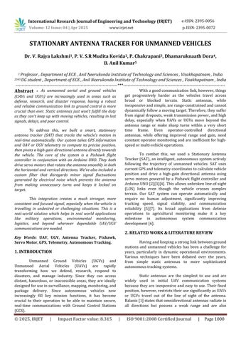
Central to the system is the Pixhawk v2.4.8 flight controller[2],whichisprovidedwithGPScoordinatesand telemetrydatafromtheUAVorUGV[3].Itissentthrough a 433 MHz telemetry module and processed in real time. The Pixhawk determines the relative position and orientation of the vehicle with respect to the ground station and provides pulse-width modulation (PWM) signals for the target azimuth (horizontal angle) and elevation(verticalangle)oftheantenna.
But PWM outputs from the Pixhawk in raw form can contain noise or jitter due to rapid vehicle position changes or electrical noise. To mitigate this, we inserted an Arduino UNO as a middleware processor. The Arduino takes the PWM input, removes the small, insignificant oscillations with a custom deadband filter, and converts thedatatosmoothservomotorcontrolsignals.
There are two MG995 servo motors used for mechanicalmotionoftheantenna:panning(azimuth)and tilting (elevation). The servos are powered by a buck converter to provide safe and controlled voltage levels. This allows the system to switch antenna orientation continuouslywithlowlatencyandhighprecision.
The overall configuration is scheduled, tracked, and visualized by utilizing the Mission Planner software thatprovidesaninteractiveinterfacetothecalibration,inflight telemetry monitoring, and firmware integration usingMAVLinkprotocol.Thisintegrationofhardwareand software maintains the antenna in proper alignment with the UAV/UGV, no matter the high-speed and volatile motion.
The functional flow of the system is illustrated in the following block diagram of the Antenna Tracker system. It highlights the coordination of the basic hardware modules and the data and power flow of the system.
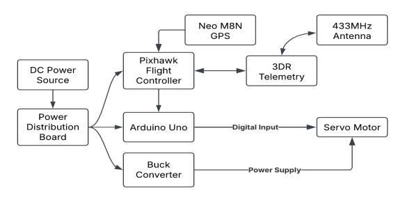
Fig3.2.1Blockdiagramoffunctionalantennatracker system
International Research Journal of Engineering and Technology (IRJET) e-ISSN:2395-0056
Volume: 12 Issue: 04 | Apr 2025 www.irjet.net
4.1 Hardware
Theantennatrackersystemisimplementedusing a set of pre-manufactured and custom modules that have been thoroughly tested for reliability, compatibility, and performanceinreal-timetrackingsituations.
1. Power Source (4-cell 5200mAh LiPo Battery): The system is powered by a 14.8V lithium-polymer battery, which hasa high capacityfor long operation. The powersourceisidealforfieldapplicationswheremobility and endurance are essential. The battery is input to a power distribution board, which feeds the necessary voltagerailstoothersubsystems.
2. Pixhawk v2.4.8 Flight Controller: Pixhawk is the primary controller for receiving the telemetry, processing GPS data, and issuing movement commands. The device features a 32-bit ARM Cortex-M4 processor operating at 168MHz, which provides real-time functionality and supports open-source firmware such as ArduPilot. The Main Output (PWM) pins on the Pixhawk areusedtosendservocontrolsignals.
3. MG995 High-Torque Servo Motor: These servo motors [9] are used to change the antenna azimuth (and possiblyelevation)angles. Withtheability toprovide 10–12kgcm of torqueand rotate180°, the MG995 offersthe power and responsiveness needed to drive directional antennas smoothly and precisely in outdoor environments.
4. Arduino UNO (ATmega328P): Arduino [5] acts as an intermediary between the Pixhawk and the servo motors. Arduino receives PWM signals from the Pixhawk, filters for noise with a deadband filter, scales the PWM signals into the motor's working range, and sends clean commands to the motor. All this filtering allows for smoothmotionwithoutjitter.
5. Buck Converter: To protect the servo motors from over-voltage, a buck converter drops the 14.8V supplytoasecurelevelof5–6V.Thiscomponentprovides stablepower supply and avoidsservo malfunctioning due tovoltagespikesordrops.
6. UBLOX NEO M8N GPS Module: On the tracker, the Neo M8N captures satellite signals and delivers highprecision real-time coordinates. It features multi-GNSS capability (GPS, GLONASS, Galileo) to support quick satellite lock and better accuracy. The information is supplied to the Pixhawk to be used in calculation of orientation.
p-ISSN:2395-0072
7. 433 MHz Telemetry Module with Antenna (3DR): A long-distance telemetry system is used to provide a bi-directional communication path between the ground tracker and the UAV. The module operates in the 433MHzfrequencybandandensurestelemetrydatasuch as position, heading, and status are transmitted in real time in a reliable way. The provided high-gain antenna providesagreatersignalreachandreadability.
When combined, these elements produced an agile, powerful and extensible system, enabling it to operate reliably in dynamic environments where timely communicationsareessential.
A combination of open-source and purpose-built software tools were unified to run and integrate the antennatrackingsystem.
1. ArduPilot Antenna Tracker Firmware (v1.1.0): This firmware enables the Pixhawk to act as a tracker antenna. It captures GPS and telemetry information, calculates the required azimuth and elevation angles, and sendscorrespondingPWMsignals.Thisrelease,published by the ArduPilot team in the year 2019, incorporates improvements in support for continuous rotation servos aswellasinbatterymonitoringcapabilities[1].
2. Arduino IDE: TheArduinoUNOwasprogrammed using the Arduino Integrated Development Environment (IDE), which is based on C/C++ semantics and allows simple uploading of control logic. A custom script was created that incorporates a deadband filter to eliminate low-level signal noise, preventing jerky servo motion. For smooth running and to achieve more accurate tracking, thedeadbandfilterisnowinitsfinalform.
3. Mission Planner (v1.3.80): MissionPlannerisan open-sourcesoftwaregroundcontrolstationforWindows that configures and monitors Pixhawk-based systems. It was utilized during this project for loading firmware, calibrating, live tracking, and system diagnostics. This softwarehasabuilt-ininterfaceforMAVLinkprotocolthat displays live UAV positioning, antenna orientation, and telemetryhealthandstatusofthesystem.
4. Shapr3D (v5.830.8600.0): Shapr3D was used to developthephysicalbodyfortheantennatracker.The3Dprinted body was made using Hyper PLA. The design development was accomplished using Shapr3D software and was exported in STL format for 3D printing using Creality-brand 3D printers. The images of the 3D models designedinShapr3Dandthe3Dprintedtrackerframecan befoundbelow.
International Research Journal of Engineering and Technology (IRJET) e-ISSN:2395-0056
Volume: 12 Issue: 04 | Apr 2025 www.irjet.net p-ISSN:2395-0072
3D Models of Tracker Frame:
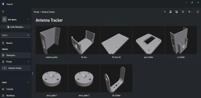
3D Printed Tracker Frame:
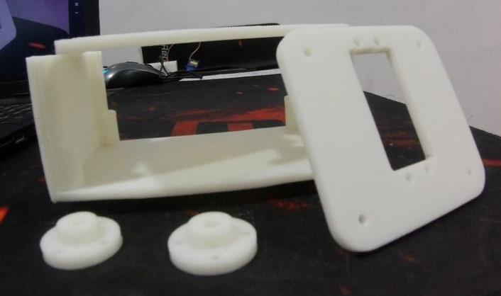
Thesetoolsnotonlyenabledstrongfirmwareand hardware integration but also provided a solid interface for control and customization. Their open-source nature allowsthemtobereadilyupdated,community-supported, and future-proofed, for example, the addition of multivehicletrackingorAIpredictionmodels.
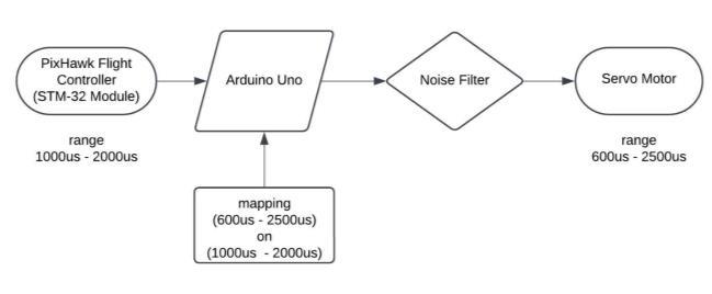
Fig5.1.1:Blockdiagramofsignalfilteringandservo controlprocessusingArduinoUNO
Oneofthemajordifficultieswithreal-timeservocontrolled systems is maintaining stable motor behavior in response to noisy signals. In the case of our antenna tracker, we use a Pixhawk flight controller, which transmits PWM (Pulse Width Modulation) signals to control the position of the directional antenna [5]. However, these signals are susceptible to rapid fluctuations caused by minor variations in telemetry or GPSdata,aswellaselectricalnoise.Ifleftunfiltered,these fluctuations lead to small, unnecessary servo movements, also known as "jitter," which degrade the stability of antennatracking.
In order to help mitigate this problem, we used a deadband filter using the Arduino UNO microcontroller. The purpose of this filter is to ignore smaller changes in input PWM values - in our case within a designated limit (e.g., ±4 units) - and allow only positive changes to pass through. This will stop the servo from reacting to every little change - hence the motion of the antenna will be smootherandthemechanicalpartwilllastlonger.
TheArduinowilltakethePWM[5]inputfromthe Pixhawk and compare it with the last value and only update the servo position if the difference is greater than the deadband range. This not only minimizes mechanical wear, but also enhances the responsiveness and accuracy ofthetrackerwhentheUAVorUGVactuallyturns.
Thecontrolflowadherestothissequence:
1. Pixhawk generates a PWM signal ranging from approximately1000-2000µs.
2. Arduino UNO captures the signal through a PWM capturelibrary.
International Research Journal of Engineering and Technology (IRJET) e-ISSN:2395-0056
Volume: 12 Issue: 04 | Apr 2025 www.irjet.net
3. It passes the value to the deadband filter to see whetherornotthechangeissubstantial.
4. If significant, the value is mapped to a 0–180° range,suitableforservocontrol.
5. ThisvalueisconvertedtotheMG995servomotor usedfortheantennamovement.
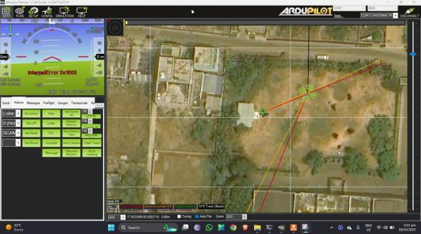
The Stationary Antenna Tracker (SAT) system that was planned was assessed for servo responsiveness, tracking stability, communication reliability, and future upgradeability. The testing was mainly qualitative due to limited availability of a higher degree of accuracy testing equipment, but the system performed satisfactorily in real-worldapplicationstypicalforthesystem.
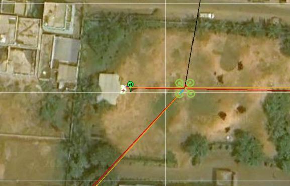
The Mission Planner software was utilized as a live interface to monitor performance in real-time and validatethetracking performance. Thesoftware provided telemetry feedback in real-time, like UAV position and direction, signal level, and antenna direction. One could seetheGPSpositionmoveasitrespondedtotheheadings, andtherewasanobservabledelayonthescreen.
p-ISSN:2395-0072
1. Stability Tracking: The system maintained a continuouslyalignedcommunicationlinkwiththemoving UAV.Dynamicallyadjusting theazimuthoftheantenna in real-time through GPS and telemetry inputs, the system was able to remove the signal dropouts typically encountered with static or manually aligned antennas. Incorporating a deadband filter within the Arduino UNO added yet another layer of smoothness, removing small jitter-induced movement and allowing the servo to operatesmoothly.
2. Servo Motion and Angular Accuracy: The MG995 servo motor was seen to track UAV heading updates with an estimated average accuracy ±3° of azimuth. This accuracy is comparable to other similar systemsdescribedintheliterature.Nugrohoetal.[1]have achieved an average tracking error of 5.62° in azimuth using a Yagi-Uda antenna [7], thereby confirming the efficacy of our filtering and control logic. The servo movement was also very responsive and fluid when switchingtargets,plusdeadbandlogicmitigatedexcessive movement due to small variations in the PWM signal. Overall, the antenna maintained a good lock on the UAV andcausedlittletimelagorovershoot.
3. Communication Range and Signal Reliability:
The high-gain omnidirectional antenna in the 433 MHz telemetry system ensuredsuccessful communication over a range of approximately 1–1.5 kilometers in an open environment. This would depend on interference and terrain but the omnidirectional antenna with a high-gain greatly reduced the chances of the signal getting weakened. This system in comparison to a simple omnidirectional system has an improved range and improvedsignalintegrity.
4. Response Time and Delay: Thesystemwasable to process GPS inputs and control the direction of the antenna with minimal latency. End-to-end latency, from thereceptionofthenewcoordinatestoservoadjustment, wastypicallybelow200milliseconds,whichwassufficient for line-of-sight maintenance with most UAV applications. There were no cases of perceivable lag encountered at normaloperatingspeeds.
5. Scalability and Future Enhancements: While thecurrentiterationoftheSATsystemisdesignedtotrack onevehicleonly,theSATsystemisadaptableandscalable. With software-based switching logic or a multi-channel controller, the SAT system can be configured to track multiple UAVs or UGVs at once. Furthermore, there are expansive opportunities for the incorporation of predictive tracking models using AI because evidence shows these models would track the UAV's flight path usingarchivaltelemetrydataandenvironmentalvariables that will allow for timely servo positioning and
International Research Journal of Engineering and Technology (IRJET) e-ISSN:2395-0056
Volume: 12 Issue: 04 | Apr 2025 www.irjet.net
confinement of the tracking latency. The results indicate theSATsystemcanbedeveloped,optimized,andusedasa practical and efficient system for real-time UAV communicationtracking.
Following future re-engineering and improvements, the SAT system may be developed for moredemandingapplicationssuchasmulti-droneswarms or autonomous delivery systems in and out of obstacles, and ultimately to assist ground field monitoring purposes withUAV-UGVcollaboration.
The Stationary Antenna Tracker (SAT) system implemented in this project is generally applicable in the majority of industries with the requirement for extended, stable, and long-range communication with unmanned ground vehicles. With the capability to accurately track real-time UGVs and UAVs, the system enhances operationalefficiencyinbothcivilianandmilitaryuses.
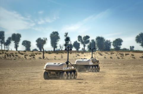
In defense and tactical scenarios, prompt data transfer and situation perception are critical. SAT technology delivers faultless command centers to unmanned surveillance drone or ground robot connectivity, providing real-time connectivity. It enables round-the-clockvideostreaming,remotesensing,andlive coordination,eveninextremeorcontestedenvironments. The tracker provides a secure, two-way directive communication capability when loss of signal may compromise mission accomplishment for border monitoringorbattlefieldreconnaissance.
Illustration: Utilizing flying drones for survey border areas or UGVs across rugged terrain using covert operationmode.
TheresearchcommunitycommonlyusesUAVsfor analyzingclimatetrends,trackinganimals,orundertaking
p-ISSN:2395-0072
geospatial studies in remote areas. Satellite-based (SAT) technologyallowsforcontinuouscommunicationbetween a drone and ground station, which allows high-definition data to come in "live". An antenna link is essential if you want to avoid the risk of losing data in a long mission, when tracking animal movements, or changes in forest cover.
Illustration: UAVs gathering air quality data in mountainousareas,withtheantennatrackerinsynceven withenvironmentalinterference.
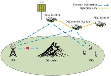
Fig7.2.1SAT-enabledantennatrackingUAVtelemetry overobstructedterrain.
7.3
In contemporary agriculture, UAVs are being increasingly employed to scan crop health, soil moisture, and irrigation regimes. The drones tend to traverse extensive areas of farmland, where fixed antennas are unable to provide coverage. Farmers can have good telemetrylinksacrosslongstretchesoflandwiththehelp of the SAT system, improving the reliability of UAV data andallowingforlesshumaninteractioninflight.
Example: Antenna-tracking drones flying above agricultural fields providing NDVI (Normalized Difference Vegetation Index) information to assess the crop condition.
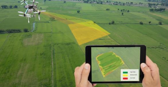
Fig7.3.1SAT-enableddronesmonitoringcrophealthusing NDVIdataoveragriculturalfields.
International Research Journal of Engineering and Technology (IRJET) e-ISSN:2395-0056
Volume: 12 Issue: 04 | Apr 2025 www.irjet.net
UAVs are deployed on search and rescue operations, and in disaster zones to assess damage, aerial mapping, victim location; SAT ensures communication withtheseUAVsisreal-time,allowinglivefeedsandrapid data transfer to rescue teams. Autonomous delivery drones used by logistics firms can also utilize the tracker to provide real-time telemetry connections along their delivery routes. Example: Disaster relief drones with live video over earthquake zones, or package-delivering UAVs overcitystreetswithlivegroundcomms.
In any of these situations, the SAT system is an importantenablerofmissioncapability,dataintegrity,and operational security. With its plug-and-play functionality, and autonomous tracking, it has the potential to enable future upgrades such as AI-based trajectory prediction andtrackingofmultipleaircraft.
The Stationary Antenna Tracker (SAT) system developed in this project is efficient in offering low-cost, fault-resistant, and autonomous methods for unbroken communication with moving UAVs and UGVs. Through utilization of real-time GPS and telemetry data and implementation of a servo-controlled tracking system through Pixhawk and Arduino, the system ensures uninterrupted directional alignment among the moving unmannedvehiclesandthegroundantenna.
In comparison to conventional stationary or manually operated antenna systems, SAT very much improved reliability of signal, accuracy of signal positioning, range of operation, and functionality. Additionally, the deadband filter stabilizes operation by eliminating standard fluctuation or jitter of servo movementthusprovidingsmoothandaccuratetrackingof the antenna while minimizing the impact of wear on mechanicalhardware.
Since the system's modularity and extensibility provide room for any number of upgrades, many possibilitiesarelaidaheadforthefuture.Theseinclude:a multi-UAVtrackingcapabilitythroughadvancedtelemetry switching or through coordination of a network, usage of AItechnologyforpredictivecontrolthatcanpreemptively direct the antennas direction based on anticipated movement of vehicles, and solar power for increased endurancewhileoperatingawayfromapowersupply.
Inshort,theSATsystembridgestheperformance and affordability gap in antenna tracking solutions, and has the potential to scale up to defense, research, agriculture, and disaster relief applications. Its practical
p-ISSN:2395-0072
applicationandupgradabilitypotentialarereasonswhyit is a highly promising platform for future development of autonomoustrackingtechnology.
[1] C. A. Balanis, Antenna Theory: Analysis and Design, 4th ed.Hoboken,NJ,USA:Wiley,2016.
[2] ArduPilot, “AT1.1.0_tracker.apj Firmware Release,” Aug.3,2019.[Online].Available:
https://firmware.ardupilot.org/Tracker/
[3] u-blox AG, “NEO-M8 Series GNSS Modules,” Datasheet, 2019.[Online].Available:https://www.u-blox.com
[4] ArduPilot, “Mission Planner Documentation.” [Online]. Available: https://ardupilot.org/planner/
[5] A. Riyandi, S. Prakoso, “PID Parameters Auto-Tuning on GPS-Based Antenna Tracker Control Using Fuzzy Logic,” Jurnal Teknologi dan Sistem Komputer, vol. 6, pp. 122–128,2018.
[6] F. Almetania, Y. Huda, “Rancangan Sistem Antenna Tracker pada Ground Station UAV sebagai Media Pantau Pasca Bencana,” Jurnal Vocational Teknik Elektronika dan Informatika,vol.10,no.3,pp.102–107,2022.
[7] G. Nugroho, D. Dectaviansyah, “Design, Manufacture and Performance Analysis of an Automatic Antenna Tracker for a UAV,” J. Mechatronics, Electrical Power, and Vehicular Technology,vol.9,no.1,pp.32–40,2018.
10. BIOGRAPHIES


DrRajyaLakshmiValluri ProfessorinECE,Head-Academics CoOrdinator,IQAC Nodalofficer,Womencell(ICC) AnilNeerukondaInstituteofTechnology andSciences.
P.V.S.R.MuditaKovida Student,DepartmentofECE AnilNeerukondaInstituteofTechnology andSciences.
P.Chakrapani Student,DepartmentofECE AnilNeerukondaInstituteofTechnology andSciences.
International Research Journal of Engineering and Technology (IRJET) e-ISSN:2395-0056
Volume: 12 Issue: 04 | Apr 2025 www.irjet.net p-ISSN:2395-0072


DhamaruknaathDora
Student,DepartmentofECE
AnilNeerukondaInstituteofTechnology andSciences.
B.AnilKumar
Student,DepartmentofECE
AnilNeerukondaInstituteofTechnology andSciences.