International Research Journal of Engineering and Technology (IRJET)

Volume: 09 Issue: 07 | July 2022 www.irjet.net
Auto Retreat Side Stand
e ISSN: 2395 0056 p ISSN: 2395 0072
1,2,3Student, Department of Mechanical Engineering, Rajiv Gandhi College Of Engineering Research and Technology, Chandrapur, Maharashtra, India
4Associate Professor, Department of Mechanical Engineering, Rajiv Gandhi College Of Engineering Research and Technology, Chandrapur, Maharashtra, India ***
Abstract - The side stand is used for supporting a parked motorcycle. Side stand in two wheeler’s function the entire weight of the vehicle when it is parked. They are perfect on quick stop when one need to leave the vehicle for short while. If the rider forget to retract the side stand before riding, then the chance of stand hitting the ground and affecting the riders control during the turn increases. In this paper the system of Auto Retreat Side Stand is designed to reduce the possibility of accident. The presented mechanism consists of 12 V geared motor powered by motorcycles battery. The system is comprised of spring loaded piston cylinder mechanism with the cam and follower mechanism. The motor is actuated by the pulse signal from reed switch sensor and magnet which is assembled to either sprocket or wheel.
Key Words: Side stand, Automatic stand, Sensor, Safety, Twowheelersidestand
1. INTRODUCTION
In modern developing world, automobile plays important role in passenger transport on land. Especially twowheeler’splayamajorroleonroad.Eventhoughthey are helpful there are some events of accidents due to careless nature of motorcyclists. A substantial number of motorcyclists suffer injuries in crashes each year for the reason of forgetting the side stand left deployed while driving on the road. However, there is no simple way to identify what percentage of motorcyclists get into accidents. This is due to the fact that many accidents go unreported. Motorcycles are generally provided with side stand for supporting them when they are not in use. Its standard form usually comprises a bar or rod which is pivoted to the lower portion of the motorcycle frame and is movable to a laterally downward extending position so thatthemotorcyclecanbetiltedagainstandrestuponthe bar. When the motorcycle is in use, the bar is swung upward and along the frame so that it will not interfere with the running of the motorcycle. Often the motorcyclists neglect to move the stand to its raised position and when a bike is tilted left while riding, the stand strikes the ground and causes the motorcycle to be thrown to the ground, generally with serious
consequences to both motorcyclists and his companion. Now a day’s sensors are used for ensure that the standis inretractedconditionbutoftenduetosomemistakesofa personsometimesstandisdeployedwithoutknowledgeof rider and the engine is suddenly stops in mid of the road andinmidofthetraffic,thisagainputthedriverinapanic situation. To avoid such risks we have designed Auto RetreatSideStand.
1.1 Aim
1) Toreducetheaccidentsofmotorcycleriderfromside standintwowheeler’s.
2) To study the method of fabrication of side stand liftingsystem.
3) Tofabricateaccordingtoselectedmethod. 4) Tostudythefutureimplementationonthesystem
1.2 Objective
1) Autoliftingthesidestand. 2) Minimizingtherisk. 3) Minimummovingcomponents. 4) Minimumbatterypoweruse. 5) The system should not interfere with manual use of sidestandbytherider
1.3 Need of Project
The side stand should lift automatically when driver forgets to lift it.. Minimizing the risk of accidents by side standwhilecorneringandobstacles.
2. METHODOLOGY
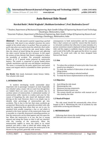
Followingchartshowsthemethodologyusedtodesign andfabricateautoretreatsidestand.
Harshal Butle1 , Mohit Waghade2 , Shubham Govindwar3 , Prof. Shailendra Zaveri4International Research Journal of Engineering and Technology (IRJET)
Volume: 09 Issue: 07 | July 2022 www.irjet.net
2.1 3D Modeling
Fig 1 : FlowChart
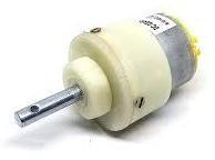
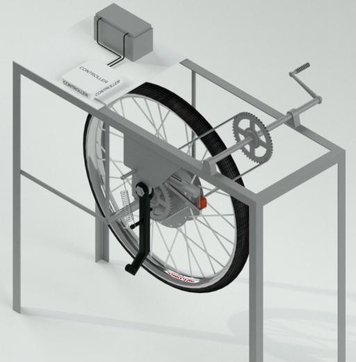
The virtual model is created by using 3D Modeling software to analyze the model. The dimensions are consideredasperthephysicalmodelandaroughdiagram oftheAutoRetreatSideStandisdrawn.
2.2 Material Selection
e ISSN: 2395 0056 p ISSN: 2395 0072
After doing research on the several material properties, the most feasible material is selected for the spring loaded piston, cylinder and other working components.Weinvestigatedforthecharacteristicswhich are taken into account, which including machinability, durability,strength,weight,availability,andmaterialcost. Amaterialwithsufficientstrengthischosentoensurethat the fabricated frame of the side stand lifter mechanism does not fail under the strain exerted. We have used cylindricalshapeforframecylinderforthisproject.
2.3 Components
2.3.1
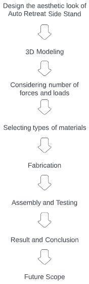
Electric Gear Motor
Fig 3 : ElectricGearMotor
A DC gear motor is a electrical motor coupled to the gear box with output of low speed high torque arrangement. A small motor is one kind of electric motor, andthemainfunctionofthisistochangetheenergyfrom
electrical to mechanical. The uses of small/mini motors involveinseveralmanyapplicationslikedesigningsample mini motor projects, CD/DVD players, hard drives, fans, pumps, coffee machines, robotic vacuum cleaners, hairdryers, mixers, bread cutters & spindle drives within modifiableorchangeablespeedapplications.
2.3.2 Wheel and Tyre
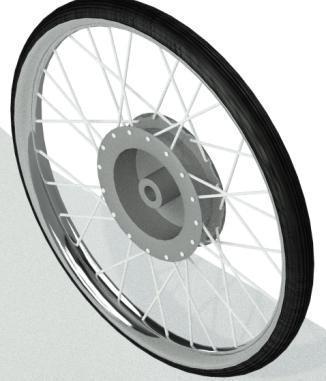
Fig 4 : Wheelrimwithtire
Fig 2 : 3DModeling(IsometricViewStandDown)
International
Research Journal of Engineering and Technology (IRJET)
Volume: 09 Issue: 07 | July 2022 www.irjet.net
The rim is the outer edge of a wheel holding the tire onit.Itmakesuptheoutercirculardesignofthewheelon which the inside edge of the tire is mounted on vehicles such as automobiles. In cross section, the rim is deep in the center and shallow at the outer edges, thus forming a "U"shapethatsupportsthebeadofthetirecasing.Wheels are used which are connected with help of axle and bearings. Spokes of wheels are made of stainless steel or high carbonsteel.
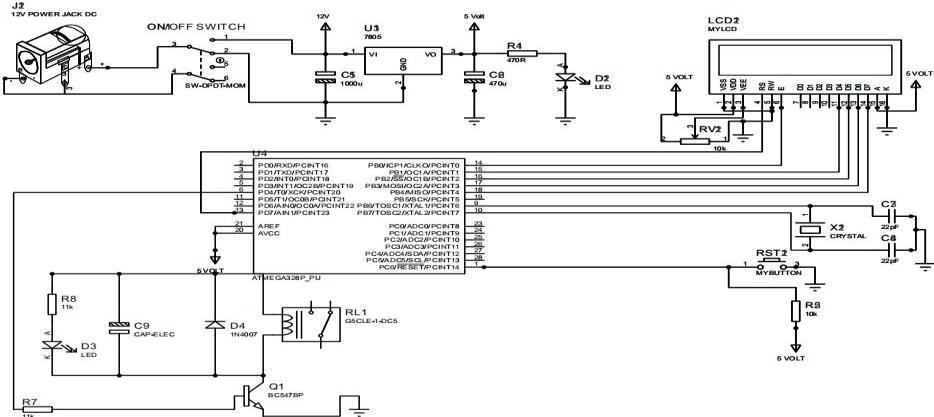
2.3.3 Controller Circuit
Fig 5 : ControlUnitCircuit
A controller circuit is used to connect all electrical and electronic components including sensors and actuators together. The controller basically acts as the “heart”forthesystem.
2.3.4 Frame Angles
e ISSN: 2395 0056
p ISSN: 2395 0072
shapeandusefulmechanicalproperties.Angleironcanbe manufactured in different steel and metal alloys, in both smaller bar sizes and larger L shape sizes. Ideal for high strength applications, L shaped angle iron is available in equalorunequalanglesteel.
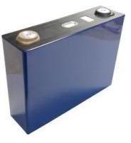
2.3.5 Lithium Ion Battery
Fig 6 :FrameAngle
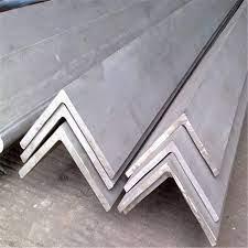
ThisisaLsectionangleframeusedforfabricationof frame structure on which components are mounted. Steel angle (also known as angle iron), is one of the most commonly used steel structural shapes due to its 90° L
Fig 7 : Lithium IonBattery
Lithium ion (Li ion) batteries are used in many products such as electronics, toys, wireless headphones, handheld powertools,small andlargeappliances, electric vehicles and electrical energy storage systems. Lithium batteries can be smaller and lighter than other types of batterieswhileholdingthesameamountofenergy
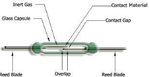
2.3.6 Reed Sensor and Magnet
Fig 8 : ReedSensor
Reed sensors use a magnet or electromagnet to create a magnetic field that opens or closes a reed switch within the sensor. This deceptively simple device reliably controls circuits in a wide range of industrial and commercialgoods.
A reed switch is a pair of electrical contacts that createaclosedcircuitwhentheytouchandanopencircuit when separated. Reed switches form the basis for a reed sensor. Reed sensors have a switch and a magnet that powertheopeningandclosingofthecontacts.Thissystem iscontainedwithinahermeticallysealedcontainer.
International Research Journal of Engineering and Technology (IRJET)
Volume: 09 Issue: 07 | July 2022 www.irjet.net
2.3.7 Chain, Sprocket, Bearing
Fig - 9 :
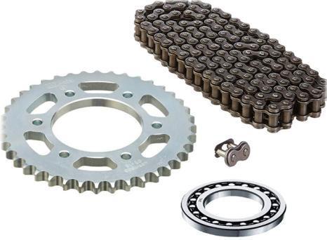
Chain,Sprocket,Bearing
Sprocketteethorcogsthat meshwithachain.These transmit rotary motion between two shafts or impart linear motion to a track,tape etc. Widelyusedin bicycles, motorcycles, cars, tracked vehicles and machinery. It is made up of Stainless steel. Ball bearing is a machine element which constrains relative motion to only desired motionandreducesfrictionbetweenmovingparts.
3.2.8 Spring
Therearetwotypesofspringsusedinthisproject.
1) Compression spring It is placed inside the cylinder. It is the key component to lift the stand up when pistonisreleased.Itstorestheenergyin,whenrider lowersthesidestand.
2) Tension spring It hold stable the side stand in both thepositions.
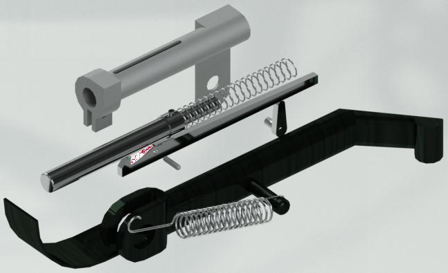
2.3.9 Other Components in Mechanism
Fig 10 : Components
inthemechanism
e ISSN: 2395 0056 p ISSN: 2395 0072
A cylindrical housing with key way slot is provided withpistonhavingsingledegreeoffreedomandspring.A lever is pivoted on the cylinder to catchlock the piston. A verticalstripwithcircularholeisweldedtowardstherear sideofthecylinderwheregearedmotorisattached.
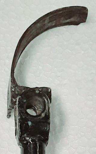
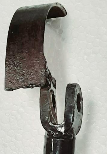
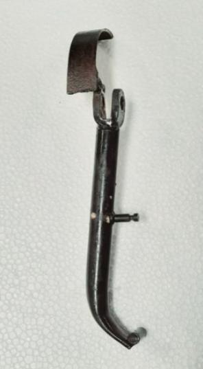
2.3.10 Modified Side Stand
A Side stand is a device on a bicycle or motorcycle that allows the bike to be kept upright without leaning against another object or the aid of a person. A stand is usuallyapieceofmetalthatflipsdownfromtheframeand makes contact with the ground. It is generally located in themiddleofthebikeortowardstherear.
Fig - 11 : ModifiedSideStand
Fig - 12 : ModifiedPartViews
In this system the side stand is modified as to be in partially contact with the piston head. A curved strip is attachedto thestand.Whenthestand isindownward
International Research Journal of Engineering and Technology (IRJET)
Volume: 09 Issue: 07 | July 2022 www.irjet.net
position the curved strip makes contact with the piston head.Whenthestandisin upwardpositionthestandwill not be in contact with piston. This curved strip also helps tolockthepistonincylinder.
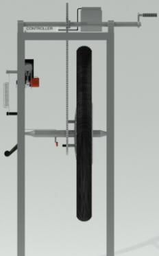
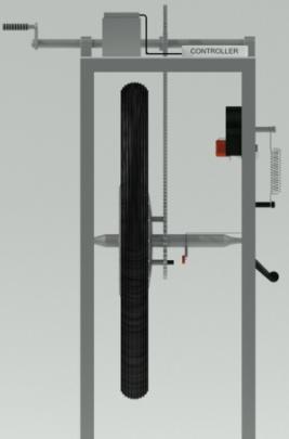
3. ASSEMBLY VIEWS
Thefollowingfiguresshowstheassemblyviewsof theAutoRetreatSideStand.
e ISSN: 2395 0056 p ISSN: 2395 0072
Fig 16 : LHSVandRHSV(StandDown)
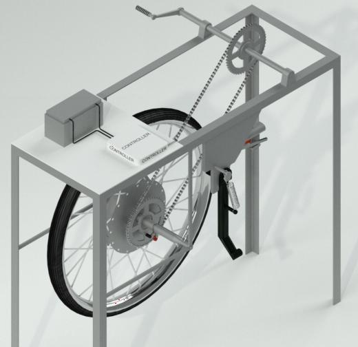
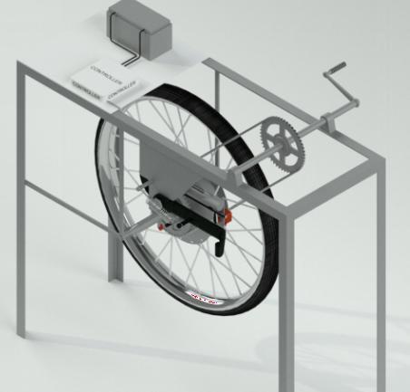
Fig - 17 : IsometricView(StandDown)
4. CONSTRUCTION AND WORKING
The project is using sensors, microcontroller and an actuator as a 12V DC geared motor to control the mechanismsofautomaticretreatofthesidestandsystem. The sensor will constantly monitor the rotation of wheel. The main control unit is connected with the sensor to receive signal. The control unit is also connected to the actuator which is connected to side stand assembly. Initially when the wheel is in the rest position, the side stand is in the deployed downward position. At this time the reed switch will not generate any pulses. The pulse generation of reed switch is dependent on rotation of wheel as magnet isattached withthe wheel arrangement. When the wheel starts to rotate the magnet also rotate alongwithit.Asthemagneticfieldpassesnearthesensor it generate a pulse and sends it to the control unit. The controlunitreceivesthesignalfromsensor.Thecontroller will send the signal to relay based on the pulses received fromsensor.TherelayclosesthecircuitfortheDCgeared motor. The cam attached to the shaft of motor lifts the follower which is pivoted to the cylinder by a pin. The follower also acts as a locking arrangement to the piston. Initially the piston is in locked position and the spring inside the cylinder is in the compressed position. As the
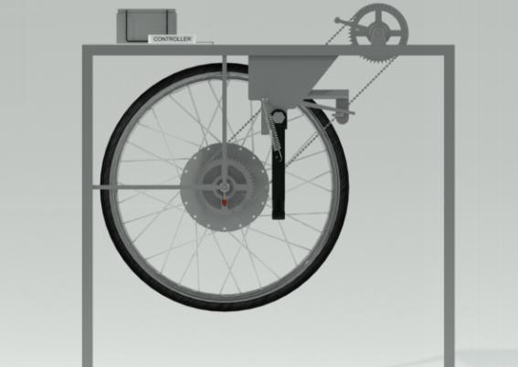 Fig 13 : IsometricView(StandUp)
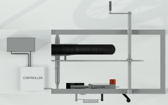
Fig 14 : FrontView(StandDown)
Fig - 15 : TopView(StandUP)
Fig 13 : IsometricView(StandUp)
Fig 14 : FrontView(StandDown)
Fig - 15 : TopView(StandUP)
International Research Journal of Engineering and Technology (IRJET)
Volume: 09 Issue: 07 | July 2022 www.irjet.net
follower rotates, it unlocks the piston. The spring forces the piston and piston further forces the metal strip attached to the modified stand. This action will result in the lifting of the stand upward The tension spring will holdthesidestandinitsupposition.
6. ADVANTAGES
1) Providessafetytotherider.
2) Automaticoperation.
e ISSN: 2395 0056
p ISSN: 2395 0072
3) Minimumpowerrequiredforworking.
4) Standcanoperatedmanuallyaswellasautomatically. 5) When battery runs out of charge it can be operated manually.
6) Itdoesnotchangeoriginalworkingsetupforside stand.
7) Costeffectiveascomparedtoothermethods.
8) Shorterresponsetime.
9) Simpleindesign.
10) Easyformaintenance.
11) Cheapincost. 12) Userfriendly. 13) Lowmaintenancecostrequired
7. DISADVANTAGES
1) To operate automatically it needs charging when batteryrunsout.
2) Needperiodicmaintenance.
3) The system may fail when sensor failed to sense the rotationofthewheel.
4) Need extra attachment to implement in non battery twowheeler's.
8. APPLICATIONS
1) Itcanbeimplementedintwowheelervehicles.
2) Thetwowheelervehiclesegment includesgeared andnongearedbikes.
3) EVbikesarealsogreattoimplementthissystem.
4) It can also be implemented in bicycle with the additionofsomeelectroniccomponentsandbattery
9. FUTURE SCOPE
1) The system can implemented in both the vehicle by makingsomechangesinarrangements.
2) Space can be minimized with the help of using small solenoidinstantofmechanicalplunger.
3) The system can be more effective and efficient, if the all electrical components are designed in single unit ofsystem.
4) The system can be implemented in another sector wherethemoreresponsivesystemisneeded.
3. CONCLUSION
As the setup is compact it takes less space than side stand itself. In future further modification can be done. When the rider forgets to lift the side stand this system will definitely help save his life. The possibilities of the accidents will definitely be reduced. This system requires
International Research Journal of Engineering and Technology (IRJET)
Volume: 09 Issue: 07 | July 2022 www.irjet.net
lowmaintenanceduetolessermovingpartswhichcanbe donewiththeperiodicmaintenanceofthevehicle.
ACKNOWLEDGEMENT
We express our heartiest acknowledgement to all those who supported us and provided valuable guidance whilst completion of this project. We would like to take this opportunity with great pleasure to express our deep sense of gratitude towards our guide Prof. Shailendra R. Zaveri for his valuable guidance and incessant encouragement and cooperation extended to us during thisdissertationwork.Wewouldliketosayspecialthanks toourHon. HeadofMechanical Department,Dr. Pravin A. Potdukhe and the incharge of workshop Shri. Thamke sir forgivingustheirvaluabletime.
REFERENCES
[1] V.Srivastava,T.Gupta,S. Kumar,V. Kumar, J.Rafiq,S. Dwivedi, IJEAT, Volume 3, Issue 4, April 2014, “AutomaticSideStand”,179 182
[2] A.SINGH,A.RAI,C.YADAV,J.YADAV,P.CHOUDHARY, IRJET, Volume: 05 Issue: 04 | Apr-2018, “Automatic SideStandoftwowheeler”,1315-1317.
[3] Gulhane, G. Gawande, B. Gawande, S. Dhule, C. Deshmukh, IJETER, “Fabrication of Automatic Side Stand Lifting Mechanism”, Volume 5, Issue 4, April (2017),7 11
[4] Akhil Ramesh, Mohammed Misfar K, Mohammed Rizwan N, Mohammed Shuaib P, Vishnu P, Sprocket Side Stand Retrieval System, International Journal of Innovative Research in Science, Engineering and Technology,Volume6,SpecialIssue4,March2017
[5] Ajournalpaper‘motorcycleaccidents casestudyand what do learn from them’ by Ecker, H. Viema UniversityofTechnology
[6] Grayson, G. and Hakkert, A. (1987) Accident analysis and conflict behaviour. In J. Rothengatter and R. de Bruin(eds)Roaduserandtrafficsafety
[7] SanjeevNK,”BikeSideStandUnfoldedRideLockLink”, International Journal of Engineering Science and Research”, ISSN: 2277 9655, Volume 2, Issue 9, September 2013.
BIOGRAPHIES
e ISSN: 2395 0056
p ISSN: 2395 0072
HarshalB.Butle B Tech student, Final year MechanicalEngineering. Rajiv Gandhi College of Engineering Research and Technology, Chandrapur,Maharashtra.


MohitP.Waghade B Tech student, Final year MechanicalEngineering. Rajiv Gandhi College of Engineering Research and Technology, Chandrapur,Maharashtra.

ShubhamS.Govindwar B Tech student, Final year MechanicalEngineering. Rajiv Gandhi College of Engineering Research and Technology, Chandrapur,Maharashtra.
Prof.ShailendraR.Zaveri Associate Professor, Department of MechanicalEngineering, Rajiv Gandhi College of Engineering Research and Technology, Chandrapur,Maharashtra.