POWER FACTOR MONITORING AND CONTROLLING FOR INDUSTRIAL LOAD USING IOT

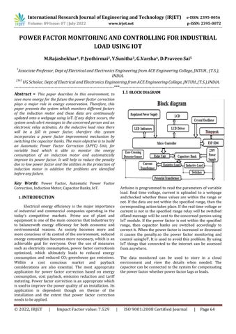
1.1 BLOCK DIAGRAM
Abstract - This paper describes In this environment, to save more energy for the future the power factor correction plays a major role in energy conservation. Therefore, this paper presents the system which monitors different factors of the induction motor and these data are continuously updated onto a webpage using IoT. If any defect occurs, the system sends alert messages to the concerned person and an electronic relay activates. As the inductive load rises there will be a fall in power factor, therefore this system incorporates a power factor improvement mechanism by switching the capacitor banks. The main objective is to build an Automatic Power Factor Correction (APFC) Unit, for variable load which is able to monitor the energy consumption of an induction motor and automatically improve its power factor. It will help to reduce the penalty due to low power factor and the utilities in the protection of induction motor in addition the problems are identified before any failure.
Key Words: Power Factor, Automatic Power Factor Correction,InductionMotor,CapacitorBanks,IoT.1. INTRODUCTION
Electrical energy efficiency is the major importance of industrial and commercial companies operating in the today's competitive markets. Prime use of plant and equipment is one of the main concerns that industries try to balancewith energy efficiency for both economic and environmental reasons. As society becomes more and more conscious of its control of the environment, reduced energy consumptionbecomesmorenecessary, whichis an achievable goal for everyone. Over the use of measures such as electricity consumption, power factor correctionis optimized, which ultimately leads to reduced energy consumption and reduced CO2 greenhouse gas emissions. Within a cost conscious market and payback considerations are also essential. The most appropriate application for power factor correction based on energy consumption, cost payback, emission reduction and tariff metering. Power factor correction isan appropriate which is usedto improve the power quality of an installation. Its application is dependent though on thesize of the installation and the extent that power factor correction needstobeapplied.
Arduinois programmed to readthe parametersof variable load. Real time voltage, current is uploaded to a webpage andchecked whether these values are within the range or not. If the data are not within the specified range, then the correspondingactiontakesplace.Iftherealtimevoltageor current is not in the specified range relay will be switched offand message will be sent to the concerned person using IoT module. If the power factor is not within the specified range, then capacitor banks are switched accordingly to correctit. Whenthepowerfactorisincreasedordecreased it causes the penalty.so the power factor monitoring and control usingIoT. It is used to avoid this problem. By using IoT things that connected to the internet can be accessed fromanywhere.
The data monitored can be used to store in a cloud environment and view the details when needed. The capacitorcanbeconnectedtothesystemforcompensating thepowerfactorwhetherpowerfactorlagsorleads.
International Research Journal of Engineering and Technology (IRJET) e ISSN: 2395 0056
Volume: 09 Issue: 07 | July 2022 www.irjet.net p ISSN: 2395 0072
2.HARDWARE COMPONENETS
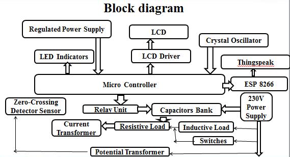
2.1 PICMICROCONTROLLER


Crystal oscillator is used in the project because of the fact thatcrystal ismore stable totemperature than othertypes ofoscillators. An oscillator is an electronic circuit that producesarepetitiveelectronicsignal.
2.4 LEDINDICATORS


Fig 2.1 Microcontroller
Below are the specifications of PIC Microcontroller Microcontroller based systems are designed to perform a specifiedtask.
2.2 REGULATEDPOWERSUPPLY
Fig 2.2
Regulatedpowersupply
The process of conversion is shown above.PIC Microcontrollerrequiresa5VDCforitsoperation. Theaimofthisblockistoconvertbatteryvoltageto5VDC
2.3 CRYSTALOSCILLATOR:
Fig 2.3
CrystalOscillator
Fig 2.4 LEDIndicators
In this project we are using LED indicators for checking Microcontroller working status and various status indications.Thisusuallyworkson2volts,10mA.
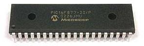
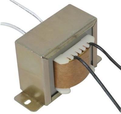
2.5 POTENTIALTRANSFORMER
Fig 2.5 PotentialTransformer
We are making use of PT (potential transformer) for capturingthezero crossingpointofvoltagewaveform. PTconvertsthehighvoltageACtoalowvoltagemeasurable quantity.PToftypestep downtransformer.
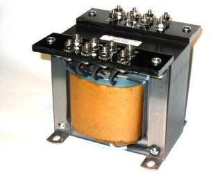
2.6 CURRENTTRANSFORMER
Fig 2.6 CurrentTransformer
International Research Journal of Engineering and Technology (IRJET)
e-ISSN: 2395-0056
Volume: 09 Issue: 07 | July 2022 www.irjet.net p-ISSN: 2395-0072

CT are used for current measurements. We are making useof CT (current transformer) for capturing the zero crossingpointofcurrentwaveform.CTisoftypestep up transformer.
2.7 ZEROCROSSINGDETECTOR
Fig 2.7 ZeroCrossingDetector

Zero crossing detection is the process of finding the variation of waveform from zero as reference point. In thisprojectthisisusedtofindoutwhether both current andvoltagewaveformsareleadingorlaggingorinphase witheachother.

2.8 RELAYUNIT
Fig 2.8 RelayUnit
A relay operation depends upon the electromagnetic effectsofcurrent flowingin anenergizingwinding.Relay is used for controlling high voltage device using low voltagesignal.Thisworksonelectromagneticprinciple.
2.9 LCDDISPLAY
Aliquidcrystaldisplay(LCD)isathin,flatelectronicvisual display that uses the light modulating properties of liquid crystals.TheLCDdisplayusedintheprojectis16X2. Weusethisdisplaytoshowthepowerfactor.
2.10 WI FIMODULEESP8266

Fig 2.10 Wi FiModuleESP8266
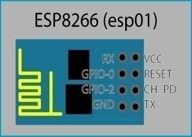
The ESP8266 is capable of either hosting an application or offloading all Wi Fi networking functions from another applicationprocessor.TheESP8266moduleisanextremely cost effective board with a huge, and ever growing, community.
3.FLOWCHART
Fig 2.9 LCDDisplay
Fig 3. FlowChart
International Research Journal of Engineering and Technology (IRJET) e ISSN: 2395 0056


Fig
International Research Journal of Engineering and Technology (IRJET) e-ISSN: 2395-0056

Volume: 09 Issue: 07 | July 2022 www.irjet.net p-ISSN: 2395-0072
6.CONCLUSION
Power factor correction equipment designed based on microcontroller and capacitor banks using IoT was used for measurement and monitoring of modelled electrical load and the following deductions were obtained:Thepowerfactorcorrectiondevicewasableto improve the power factor from 0.76 to 0.97 under the test load conditions. The average savings in energy consumption were about 1.7% of the designed load and different load patterns. With the proper amount of reactive power compensation, the system capacity is released as there is a reduction in current drawn. The economic analysis suggested the payback period to be around9monthswithasignificantamountofsavingsin energycost.
7.FUTURE SCOPE
In future this method will be implemented in most of the organization and industry. It can be implemented even in the small-scale industries because energy conservation and paying penalty cause a major issueinallscaleindustryandthismethodrectifiesallthe problem and so this will be a compulsion to minimize their expenses. This will be the best solution in future because man power will be eradicated completely and willbeautomated.Thiswillplayamajorroleinit.
REFERNCES
[1] Divya Joy, Roopitha Kaimal, Ans Alias and Anna Baby,“SmartMonitoring andPowerFactorCorrectionof Distribution Transformer using IoT”, Global Research and Development Journal for Engineering, National ConferenceonEmergingResearchTrendinElectricaland ElectronicsEngineering,March-2018,ISSN2455-5703.
[2] Yasin Kabir, Yusuf Mohammad Mohsin and Mohammad Monirujjaman Khan1 “Automated Power Factor Correction and Energy Monitoring System”, IEEE,2016.
[3] Muhammad Bilal Khan, Muhammad Owais, “AutomaticPowerFactorCorrectionUnit”,IEEE,2017.
© 2022, IRJET | Impact Factor value: 7.529 | ISO 9001:2008 Certified Journal | Page68