International Research Journal of Engineering and Technology (IRJET) e ISSN: 2395 0056

Volume: 09 Issue: 06 | Jun 2022 www.irjet.net p ISSN: 2395 0072
International Research Journal of Engineering and Technology (IRJET) e ISSN: 2395 0056
Volume: 09 Issue: 06 | Jun 2022 www.irjet.net p ISSN: 2395 0072
1* Senior Engineer, Thermal Business Unit, L&T Technology Services Ltd., India 1Assistant Manager, Product Development, CEAT Tyre, India 1Aviraj Singh, L&T Technology Services Ltd., India ***
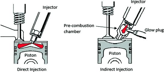
Abstract An idea of fuel injector is proposed that can improve the air fuel mixing capability by spreading it more and creating swirl action without any modification in air flow manifold. For CI engine direct injection engine, fuel doesn’t reach every region of combustion chamber injected by normal fuel injector. These left out regions have low air fuel mixing velocity and hence are not mixed properly. In new fuel injector the motion of plunger is converted into rotational motion that spreads the fuel throughout in the combustion chamber. The related numerical research of the in cylinder velocity, fuel/air mixing process, and emission characteristics of a diesel engine was performed. The numerical results showed that the new fuel injector had a positive effect on improving fuel/air mixing process by spreading the fuel more compared to normal fuel injector, which could improve the fuel utilization and reducing its consumption leading to reduction in harmful emissions such as NOx, CO and HC. The improvement in air fuel mixing showed favorable reduction in NOx by 8.44%, reduction in CO by 8.69% and reduction in HC by 8.56%, showing that it has better performance than normal fuel injector
Key Words: Fuelinjector,emission,ICengine,equivalence ratio
Sincepollutioniscausedbyvarioussources,itrequiresan integrated and multi disciplinary approach. The different sourcesofpollutionhavetobeaddressedinanintegrated approachtoachievetheobjectiveofacleanerenvironment. Air pollutants such as carbon monoxide, nitrogen oxides, particulatematter,volatileorganiccompounds,andbenzene are emitted into the environment by motor vehicles. Air pollutantscancontributetourbanairqualityproblems,such asphotochemicalsmogandadverselyaffecthumanhealth. Incompletecombustionleadstohighemissions,whichisa substantial source of air pollution, especially for the soot. Due to the impact on air pollution, the government introduced several emission regulations [1]. Incomplete combustionleadstohighemissions,whichisasubstantial source of air pollution, especially for the soot [2]. In completecombustionisgenerallyduetopoormixingofthe air and fuel, insufficient residence time, insufficient temperature and low total excess air [3]. After treatment devices can reduce the harmful emissions to meet the
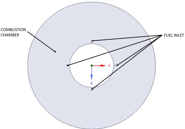
stringent emission regulations. For example, the diesel particulatefilter(DPF)isaneffectivesootpost processing equipment,followedbySCRtowardsreducingNOx. Improvingairfuelmixingefficiencyisthekeyareatoreduce shootandNOx.Toachievebetterairfuelmixing,swirlflow is generated that enhances turbulence intensity which controlscycle to cyclevariation,combustionefficiencyand exhaust emission in internal combustion engines. Swirl is usedtospeedupthecombustionprocessinSIenginesandto increasefastermixingbetweenairandfuelinCIandsome stratifiedchargeengines[4 7].Extensiveresearchhasbeen conducted to improve fuel air mixing capability. For example,toimprovethein cylinderfuel/airmixingprocess of heavy duty diesel engines, optimize the combustion processandreducethesootemissions,anewdevicenamed fuel split device was proposed. This device had a positive effectonimprovingfuel/airmixingprocessbysplittingthe fuelspray,whichcouldin creaseairutilisationandleadto efficientcombustion,multi vortexstructurecouldbeformed during the fuel injection process, which could greatly improvethefuel/airmixingprocessthatultimatelyreduced HC, CO and soot emissions [8]. In another study, a bump combustionchamberwasdesigned,whichwascharacterized by some rings on the combustion chamber wall. With the bump ring, the spray generates a secondary jet after impingingthebumpringthatdecreasesthewettingandrich mixturelayerregiononthewall,whichledtothereduction of both NOx and soot emissions at low load [9]. In determining the effect of air fuel mixture on emission equivalence ratio becomes a major parameter. Higher equivalenceratiostendtoresultinlessNO2,maybebecause of lower concentrations of O2 for oxidising NO to NO2. A higher over all equivalence ratio than the stoichiometric value results in lower NOx emissions. For all the overall equivalence ratios tested here, the NOx emissions tend to decreasearoundthericher mixtureequivalenceratio[10]. The optimization of the fuel/air mixing process on diesel engines is still of great interest. To improve the fuel/air mixingprocess,anewdesignoffuelinjectorispro posedin thisstudy.Inthisconceptoffuelinjector,fuelissprinkled throughout the engine as explained in Fig.1. With normal injectiontherearemanyareasleftunaffectedleadingtoless equivalenceratio,whereasinnewfuelinjectorasfuelleaves orifice, it reaches more volume compared to normal injection.Followedbymaximumvolumecoverage,newfuel
International Research Journal of Engineering and Technology (IRJET) e ISSN: 2395 0056
injectorguidesthefueltohaveswirlformationthatleadsto better air fuel mixing. In this study we compared the performance of 4 port fuel injector and new fuel injector basedonequivalenceratioanditsimpactonemissionsuch asNOx,COandHC.
exhaust emissions. For internal mixing operations, fuel injectorscanbeclassifiedintotwobasictypesofinjection,
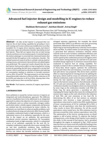
DirectInjection:Directinjectionmeansthatanengineonly hasasinglecombustionchamberandthatthefuelisinjected directlyintothischamberasshowninfig.2[12].Thiscanbe doneeitherwithablastofair.Directinjectioniswell suited forahugevarietyoffuels,includingpetrolanddieselfuel.
Indirect injection: In an indirect injected engine, there are twocombustionchambers:amaincombustionchamber,and a pre chamber [13] that is connected to the main one, as showninfig.2.Thefuelisinjectedonlyintothepre chamber (whereitbeginstocombust),andnotdirectlyintothemain combustion chamber. Therefore, this principle is called indirectinjection.
Theprimitivefeaturesofdesignandthetransientnatureof the flow through these systems makes it very difficult to analysethemexperimentally.Simulationtestsareoftenused to analyse the flow inside the injectors and provide the physicalflowprocessesvisibilitythatoccursinthemandthe entirefuelsystem.Tohaveagoodalternative,computational flow dynamics analysis (CFD) of flow through the injector wasperformed.Dependingonthecomputingsolver,there are many ways tosimulate the movement of the elements [11].However,suchanapproachincreasesthedifficultyof mesh generation for complex shapes of injectors. It is possible to carry out the whole analysis including the geometry preparation and model discretization in Ansys Fluent software. Injector designing is still challenged by con-stant striving to improve eco nomic and ecological aspectsincombustionengines,alternative fuelsupplyand varied injection pressure. This paper focuses on the developmentofthemodelofdieselfuelinjector,usingAnsys Fluent. To carry out the simulation in the simplest way possible,a2Dsectionoftheenginewastakentosimulatetwo differentconditions.Inthefirstcondition,normalinjection wassimulated,andinotherconditionsnewfuelinjectorwas simulated. New fuel injector has a rotational phenomenon wherethefuelinjectorrotatesataparticularangletospread thefuelthroughouttheengine.CFDtoolsareoftenappliedto simulateparametersoftheflowinsidetheengine,whichare difficult and sometimes impossible to mea-sure experimentally.Inthenumericalsimulation,weevaluatedthe impactoftheequivalenceratiousingamodelwedeveloped usingMATLAB.
Anidealfuelinjectionsystemcanpreciselyprovidetheright amount of fuel under all engine operating conditions and hencecanpreciselycontrolair fuelratio,whichallows,for instance: easy engine operation even at low engine temperatures (such as a cold start), precisely governed enginespeeds,goodfuelefficiency,andthelowestachievable
Fig 2:DirectvsIndirectfuelinjection.
Direct injection diesel engines have been widely used on heavydutyapplications.Recentlytheyhavebecomepopular on light duty applications because of their inherent high thermal efficiency and low CO2 emissions. However, reduction of NOx and Particulate emissions emitted from direct injection diesel engines is of urgent necessity since emission regulations have become stringent from a standpointofpreservingtheenvironment.Inordertoreduce NOx emission, injection timing retard and EGR have been employedtoreducetheinitialburningratebycontrollingthe combustion temperature and oxygen concentration.[14] However, it is difficult to reduce both NOxand particulate emissions simultaneously. Some of authors have been reportedthatNOxemissioncouldbereducedunderfuel rich andstrongswirlconditionsattheinitialburningstage[14]. Inourproposeddesign,wedesignedadirectinjectionfuel injector where the fuel in sprinkled inside the engine in a curvedtrajectoryleadingtoswirlformation.
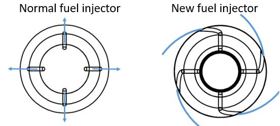
A fuel injector consists of few basic components such as Needlevalve,Compressionspring/solenoidactuator,Nozzle and Injector body. The Nozzle is the part of the Injector throughwhichthefuelisinjectedintothecylinder.BelowFig. 3isaschematiccross sectionrepresentationthecomponents offuelinjector.
Volume: 09 Issue: 06 | Jun 2022 www.irjet.net p ISSN: 2395 0072 © 2022, IRJET | Impact Factor value: 7.529 | ISO 9001:2008 Certified Journal | Page
International Research Journal of Engineering and Technology (IRJET) e ISSN: 2395 0056
Volume: 09 Issue: 06 | Jun 2022 www.irjet.net p ISSN: 2395 0072
In order to carry out simulation using Ansys Fluent 21, a simplistic2DmodelwascreatedusingSolidworks2017.This 2D model was created based on the cross section as seen from the top of a diesel engine’s combustion cavity, as mentionedinTable1[16].The2DCADrepresentationofthe samewhichhasbeenusedformodellinghasbeenmentioned inFig.5.Thedimensionofcombustionregionusedunderthis study is mentioned in Fig.6, representing bore and combustioncavityregion.
Towardstheaimtohavemaximumvolumecoverage,new fuelinjectorguidesthefueltohaveswirlformationthatleads to better air fuel mixing. In this study we com pared the performance of 4 port fuel injector and new fuel injector towardsemissionreduction.Intheproposednewdesignof fuel injector, the nozzle part is modified where a rotor is added as shown in Fig. 4. As the plunger moves up, fuel supplyiscreatedandfuelenterstherotorfromnozzle.The rotationofrotorisbasedontheprincipalofcamandfollower mechanism.Plungerisdesignedtohaveacamattachedtoit, making the entire plunger as cam. The rotor attached to nozzle has a follower path in it that is in contact with plunger’scam.Therotor’sfollowerisgivenacurvespaththat thelinearmotionofplunger(upanddown)isconvertedinto rotationalmotionofrotor.Astheplungermovesup,thefuel supplyopensandparallellyrotorrotatessprinklingthefuel throughout the engine, covering all the regions where the normalfuelinjectorfailstoreach.Thestructureofthenozzle isdesignedtohaveabearingattachedtoit.Theoutersurface of bearing is in contact with nozzle body and the inner surfaceofbearingisholdingtherotor,thatcausesittorotate astheplungermakesitslinearmotion.Thefuelinjectoris designedtowithstandhightemperature andpressureand hence the material most suitable for such condition is carburizedormaragingsteel[15].
Fig -5: 2DCADrepresentationofcombustionchamber
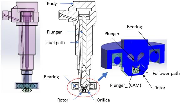
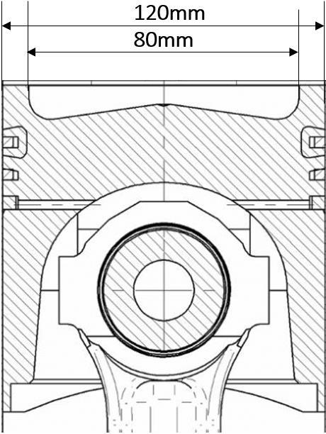
Fig 6: Frontview crosssectionofcombustionchamber
Fig 4: NewFuelInjectorCross sectionview
International Research Journal of Engineering and Technology (IRJET)
e ISSN: 2395 0056
Volume: 09 Issue: 06 | Jun 2022 www.irjet.net p ISSN: 2395 0072
Model PS10
PowerHP/kw 10/7.35
SpeedRPM 1000
BoreMM 120
StrokeMM 139.7
CubicCapacityCC 1580 CompressionRatio 1:18
FuelConsumption(max) 1970g/hr(2.37Lit/hr)
InjectionPressure(MPa) 150
Lubricatingoilconsumption 10cc/hrmax
Fuel HSDO/LDO
Lubricatingoil YENTROL 32B/SAE 30/40
NetWeightKg 320 GrossWeightKg 410
PackingSize 105X70X114CMS
Aftersimulation,pressurecontoursweretakenatthecenter ofBTPfluidvolumeasshowninaboveFig.13.Asstatedin lastparagraph,thesamecanbeobservedthroughpressure contours.Pressureattheinletismaximumforpattern2(A2 and B2) as the area is less at the entrance and as it approachesexit,pressurereduces.
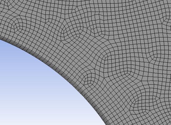
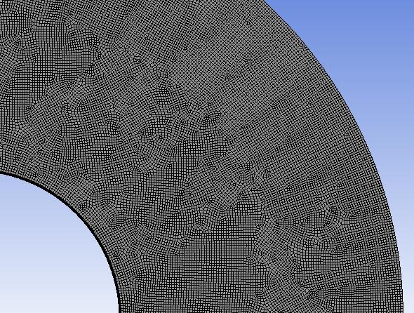
Forthesakeofoptimizingcomputationaltimeandefforts,a 2Dcrosssectionin sidethecombustionchamberwassliced out for our study. This cross section was meshed using quadrilateraldominantmeshesusingAnsysFluentMeshing, asshowninFig.7.Thesizeofeachmeshwaskeptat0.1mm toaccuratelycapturethemixingphenomenonbetweenair anddiesel.Sincequadrilateralmesheshavetheadvantageof capturinglocalgeometrymoreaccurately,itwasconsidered as opposed to triangular meshes [17]. Besides, layers of inflationlayershavebeenadded(asshowninFig.8)to wards the inlet walls as these help in capturing the near wall phenomenonmoreaccurately[18].
All For most IC engine simulations, the validation of the engine parameters is carried out using a 3D model of IC engine.However,thisrequiresalotofcomputationalpower andresources.Hence,inordertosavecomputationalefforts, the simulations for the given case were performed in 2D using Ansys Fluent CFD models. To achieve the results as closetoasanactualICenginesimulation,acomparisonwas madebetweenthesimulationresultsofthenewproposed design of IC engine with advanced fuel injector and an existing diesel IC engine, details of which have been mentionedinTable1.Theboundaryconditionsusedduring simulationhavebeenmentionedinTable2:
Values/Model
SolverType Pressurebased SolverTime Transient Turbulencemodel RNGk ɛ
Combustionmodel SpeciesTransport TurbulencechemistryInteraction model Eddydissipation
A pressure based solver with transient conditions was considered.Duringtheprocessofairfuelmixtureinsidethe combustion chamber, turbulence is created. Hence, a turbulencemodel,whichisRNGk ɛwasconsidered.Inmany cases STD k epsilon model is used for diesel combustion simulations.ButSTDk epsilonmodelsometimesgiveslarge turbulence viscosity values which in turn produces an unrealisticflowbehavior.Thus,inordertogetarealisticflow behavior, RNG k ɛ turbulence model is preferred. This is becausesomeadditionalconstantshavebeenintroducedin the RNG k ɛ model which neutralizes the large values of turbulence viscosity, thereby producing a much more
International Research Journal of Engineering and Technology (IRJET)
e ISSN: 2395 0056
Volume: 09 Issue: 06 | Jun 2022 www.irjet.net p ISSN: 2395 0072
realisticflowbehavior[19].Theequationsusedforatypical RNGk ɛmodelhasbeenshownin(1)and(2).
(1)
(2)
where, k=turbulentkineticenergy ɛ=rateofdissipationofturbulentkineticenergy ui=velocityinagivendirection αkandαε=inverseeffectivePrandtlnumbersfor and μeff=effectiveviscosity
Gk = generation of turbulence kinetic energy due to the meanvelocitygradients
Gb = generation of turbulence kinetic energy due to buoyancy
YM= contribution of the fluctuating dilatation in compressibleturbulencetotheoveralldissipationrate SkandSε=userdefinedsourceterms
Adirectrepercussionofanincreaseinfuel airequivalence ratioisthereductionof.Henceitisimperativetostudythe changeinfuel airequivalenceratiofromtheexistingdiesel enginetotheproposedconceptofnewengine.Inordertodo that, a combustion study was done using the species transport model of combustion. In a diesel engine, a large partofthecombustionoccursasaresultoftheturbulence occurring between the air and diesel mixtures. Hence, the turbulence chemistry interaction model needs to be accuratelymodeled.Todothis,Eddydissipationmodelwas used.
Inaneddydissipationmodel,combustionoccursassoonas there is turbulence and no external source of ignition is required,quitesimilartothewayadieselengineworks.The reactantsstarttoigniteoncetheyareinsidethecombustion chamberorthecomputationaldomain[20].
Once the entire combustion is completed, the fuel air equivalenceratio(representedbyϕ)fortheexistingmodel and the proposed new model can be compared to see the improvement.Fuel airequivalenceratiocanbecalculatedas performulamentionedbelow: where m represents the mass, n represents a number of moles,subscript st standsforstoichiometricconditions.
Parameters Values/Model Meshsmoothingmethod Diffusion
Layeringmethod Heightbased Remeshingmethod Methodbased
Minimumlengthscale 0.01mm
Maximumlengthscale 0.2mm
MaximumCellSkewness 0.95 Table -3: Simulationboundaryconditions
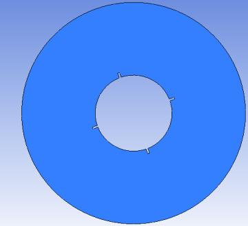
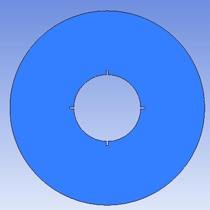
Further,incaseoftheproposednewmodeloftheengine,the fuelinjectorsneedtobegivenacircularmotion.Todothis, dynamicmeshinghasbeenused.Dynamicmeshingenables to model such geometries where the shape of the computational do main varies with time. The parameters usedindynamicmeshinghavebeenmentionedinTable3.A pictorial comparison of a dynamic meshed domain with a regularcomputationaldomainhasbeenshowninFig.9(a,b) respectively.
(a) (b) Fig -9: Thisisafigureofmeshdomainsusedfor simulation,theyshouldbelistedas:(a)Regularmeshed domain;(b)Variablemesheddomain
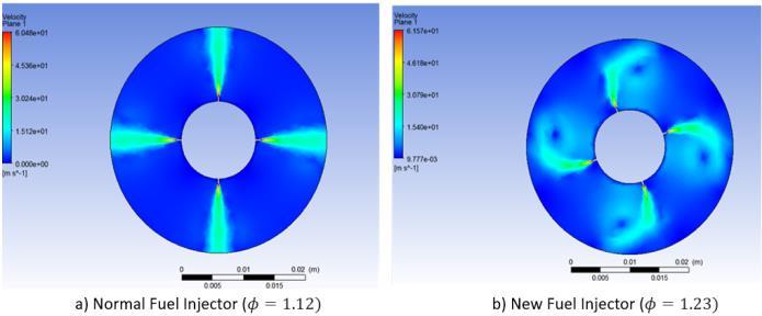
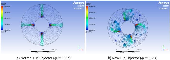
Inordertoinvestigatetheairfuelmixingperformance,the changeinequivalenceratiowascalculatedbasedontheof normalinjectorandnewdesignedinjector.Fig.10showsthe difference in fuel spread between normal and new fuel injector. Upon deriving the area of fuel coverage, the new injector spreads the fuel more compared to normal fuel injectorandsoitisevidentinthevelocitycontoursshownin Fig.10(a,b).Withbettersprayingoffuel,moreareaisbeing coveredandfollowedbyswirl formationleadingtohigher equivalenceratio.
2022, IRJET | Impact Factor value: 7.529 | ISO 9001:2008 Certified Journal
International Research Journal of Engineering and Technology (IRJET) e ISSN: 2395 0056
Volume: 09 Issue: 06 | Jun 2022 www.irjet.net p ISSN: 2395 0072
Withbetterfuelairmixingandchangeinequivalenceratio, combustion process is affected which also changes the amount of emissions being produced [21 23]. It can be expected to have cleaner burn [23] and higher Indicated mean effective pressure [22]. Higher Cylinder pressure duringcombustionphaseisalsoachievedwithbetterfuelair mixing[23].Withthesameamountoffuelbeingsuppliedto boththesetups,newfuelinjectorprovidedbettermixingand spread as evident from equivalence ratio and fuel area coverage.
Thedevelopmentofnewinjectorwastoachievebetterfuel air mixing with an aim towards lower emissions. NOx emissions are mainly affected by temperature, oxygen concentrationandreactiontime[22].Asthebetterfuel air mixing is achieved, oxygen concentration through the combustion chamber improves as the fuel spread is more. Thisgivefastercombustionreactiontimesandreducesthe amountofNOxbeingproduced[22].Also,withbetterfuel air mixinghighercombustiontemperatureisachieved.Dueto thismoresootisoxidizedandamountofsootformedwillbe reduced.TheHCandCOmasswillalsobereducedduetothe improvedfuel airmixtureandfasterrateofcombustion[21 23].
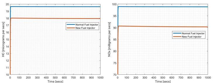
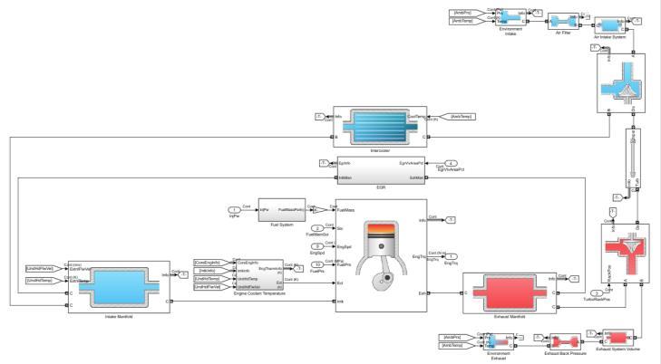
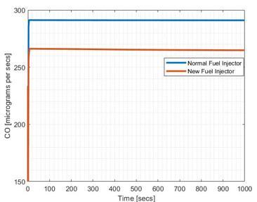
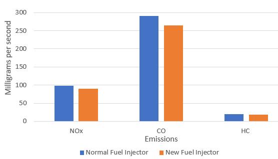
With increase in efficiency [22], the amount of fuel being consumed will reduce, which might further reduce the emissions.So,toverifythisanexistingSimulinkmodelwas used [23]. A 4 cylinder diesel engine model was used for MATLABsimulationasshowninFig.11,wheretheinputsto modelwhereenginespeedandload.Firstanormalinjector emissionsreadingswerenotedatconstantenginespeedand RPMandthennewfuelinjectorwassimulatedtoobservethe difference. A pattern in emissions throughout can noticed shown in Fig. 12, as with the same amount of fuel and injectionperiod,theemissionlevelinnewfuelinjectorisless forallparameterscomparedtonormalfuelinjector.
Inthisstudy,anewfuelinjectorconceptwasinvestigatedto improvethefuel/airmixingprocessfordieselengineat.The in cylinder velocity fields, fuel/air mixing process and emissions characteristics were analysed by numerical simulation. Compared to the normal fuel injector the rotationalactionoftherotorledairfuelmixingintoaswirl
International Research Journal of Engineering and Technology (IRJET) e ISSN: 2395 0056
Volume: 09 Issue: 06 | Jun 2022 www.irjet.net p ISSN: 2395 0072
action that ultimately led to an increment of 9.8% in equivalence ratio. The simulation was further analysed in MATLAB Simulink to observe its effect on emission. The improvement in equivalence ratio showed favorable reductioninNOxby8.44%,reductioninCOby8.69%and reductioninHCby8.56%asshowninFig.13.Inessence,the concept of the new fuel injector led to increment in equivalencethatultimatelyledtoreductionofNOx,COand HCby8.56%onanaverage.
Iamextremelygratefultomyguide,Mr.RajamaniA.(Project Lead;CFDteam;L&TTechnologyServicesLtd.,India),forhis invaluableadvice,continuoussupport,andpatienceduring my research work. His immense knowledge and plentiful experience have encouraged me in all the time of my professionalresearchwork
[1] Sunil Guliaa, Nidhi Shuklaa, Lavanya Padhib, Parthaa Bosub, S.K. Goyala, Rakesh Kumarc, Evolution of air pollutionmanagementpoliciesandrelatedresearchin India, Environmental Challenges, Volume 6, January 2022,100431
[2] A. Malmgren, G. Riley, Biomass Power Generation, Comprehensive Renewable Energy, Volume 5, 2012, Pages27 5
[3] S. Caillat, E.Vakkilainen, Large scale biomass combustionplants:anoverview,BiomassCombustion Science,TechnologyandEngineering,2013,Pages189 224
• Schematic of an existing injector was studied to understand it operation. New design is proposed with modified nozzle part, where rotor is added housedinabearing. Tocreateaswirltypemotiona camandfollowermechanismisusedtoconvertthe translation motion of injector plunger to rotatory motionoftherotorwhenthefuelisinjected.
• A2 DModelwascreatedforcrosssectionofdiesel enginecombustionchamber.A2Dsimulationwas doneusingAnsysFluentwithmeshsizeof0.1mmto capturethemixingphenomenonbetweendieseland air. Furthermore, dynamic meshing was used to simulaterotatorymotionoftheimprovedinjector.A comparison was made between the simulation resultsofthenewproposeddesignoffuelinjector andanexistingDieselICengine. Itwasnoticedthat the fuel spread increased and was covering more areacomparedtonormalinjector.Thisresultedin increasedfuel airequivalenceratio.
• Astudyforchangeinemissionswasdonebasedon increased fuel air mixing and higher equivalence ratio. With better fuel air mixing and higher equivalence ratio, increased engine efficiency and lowerNOx,COandHCemissionswereanticipated. Theeffectsofincreasedefficiencyonemissionswere alsostudiedusinganexistingSimulinkmodel.With increaseinefficiencytheoverallemissionreduction wasalsonoticedinthetestmodel,whichshoweda reduction of 8 9% for NOx, CO and hydrocarbons (HC).
[4] S. Bari, Improving Air Fuel Mixing in Diesel Engine FuelledbyHigherViscousFuelUsingGuideVaneSwirl and Tumble Device (GVSTD), Conference: SAE InternationalAt:Detroit,USA
[5] J.Benajes,J.Benajes,JoseMGarcia Oliver,J.M.Riesco Ávila ,The effect of swirl on combustion and exhaust emissions in heavy duty diesel engines, October 2004Proceedings of the Institution of Mechanical Engineers Part D Journal of Auto mobile Engineering 218(10):1141 1148
[6] R Thundil, Karuppa Raj, Manimaran Renganathan, Penerbit Akademia Baru, Effect of Swirl in a Constant Speed DI Diesel Engine using Computational Fluid Dynamics,January2012,CFDLetters
[7] MahmutKaplan,Influenceofswirl,tumbleandsquish flows on combustion characteristics and emissions in internal combustion engine review, October 2019, International Journal of Automotive Engineering and Technologies
[8] Caifeng Hao, Zhen Lu, Yizhuo Feng, Honglin Bai, Optimizationoffuel/airmixingandcombustionprocess in a heavy duty diesel engine using fuel split device, AppliedThermalEngineering186:116458
[9] W. Su, T. Lin, Y Pei, A compound technology for HCCI Combustion in a DI diesel engine based on the multi pulseinjectionandthebumpcombustionchamber,SAE TechnicalPaper
[10] Shudo, Toshio; Omori, Kento; Hiyama, Osamu, NOx reductionandNO2emissioncharacteristicsinrich lean combustion of hydrogen, International Journal of HydrogenEnergy
[11] MargotX.,HoyasS.,FajardoP.,PatounaS.,Mathematical andComputerModelling.52,2010,1143 1150
[12] Global Fuel Economy Initiative. 6 October 2012. Retrieved1May2014.
[13] Hawks,Ellison(1939).Howitworksandhowit'sdone. London:OdhamsPress.p.75.
2022, IRJET | Impact Factor value: 7.529 | ISO 9001:2008 Certified Journal | Page3452
International Research Journal of Engineering and Technology (IRJET) e ISSN: 2395 0056
[14] S.Kaleemuddin,S.Shaikh,S.Bhattacharya,Experimental studyontwo cylinderdirectinjectiondieselenginefor BS IIIemissioncompliant,InnovationsinFuelEconomy andSustainableRoadTransport,2011,Pages211 228
[15] Michael J. Pollard, Petr Michlik, Jeff A. Jensen, Scott A. Johnston,PingshunZhao,US20100025500A1,Materials forfuelinjectorcomponents
[16] PS10,EngineParameters
[17] Mark Drela, Marshall C. Galbraith, Robert Haimes, Steven Allmaras, Hybrid Shell Model for Aeroelastic Modeling,January2019
[18] Whydoweneedinflationlayer
[19] Pertti Taskinen, Modeling Study of Turbulence in a Medium Speed Diesel Engine with the RNG k epsilon model
[20] The Generalized Finite Rate Formulation for Reaction Modeling
[21] HanSangwook, Kim Jaeheun,BaeChoongsik, Effectof air fuel mixing quality on characteristics of conventionalandlowtemperaturediesel
[22] Ruomiao Yang, Xiaoxia Sun, Zhentao Liu, Yu Zhang, A NumericalAnalysisoftheEffectsofEquivalenceRatio Meas urement Accuracy on the Engine Efficiency and EmissionsatVariedCompressionRatios,August2021
[23] Dockoon Yoo, Duksang Kim, Wook Jung, Nagin Kim, Optimizationoffuel/airmixingandcombustionprocess in a heavy duty diesel engine using fuel split device, October2013
[24] CIEngineDynamometerReferenceApplication,Explore the CI Engine Dynamometer Reference Application MATLAB&Simulink MathWorksIndia
ShubhamShrivastava
SeniorEngineer(ThermalProducts)
L&TTechnologyServicesLtd. 4.5yearsofexperienceinICECooling andEVBatteryThermalManagement System


AnirbanGhosh AssistantManager CEATTyre 4.5 years of experience in product designanddevelopment
AvirajSingh
L&TTechnologyServicesLtd. MSinAutomobileEngineering HAN University of Applied Sciences, Netherlands
Volume: 09 Issue: 06 | Jun 2022 www.irjet.net p ISSN: 2395 0072 © 2022, IRJET | Impact Factor value: 7.529 | ISO 9001:2008 Certified Journal