International Research Journal of Engineering and Technology (IRJET) e ISSN:2395 0056

Volume: 09 Issue: 06 | June 2022 www.irjet.net p ISSN:2395 0072
International Research Journal of Engineering and Technology (IRJET) e ISSN:2395 0056
Volume: 09 Issue: 06 | June 2022 www.irjet.net p ISSN:2395 0072
*
1S Solomon Raj ,2
Venkata Sushma Chinta , 3Zain Afridi1Associate Professor, Department of mechanical Engineering, Chaitanya Bharathi Institute of Technology (A), Hyderabad 75
2Assistant Professor, Department of mechanical Engineering, Chaitanya Bharathi Institute of Technology (A), Hyderabad 75
3 M.tech student, Department of mechanical Engineering, Chaitanya Bharathi Institute of Technology (A), Hyderabad 75 ***
Abstract: Composite materials have intrinsic coupling effects which pave way for the design engineer to stitch them to suit for a given application. In this paper, the wing of an unmanned aerial vehicle is designed using different materials and the performance is evaluated in terms of stiffness and weight. Wing consisting of ribs, spars and skin are modified for weight minimization without reducing the specific strength and stiffness NACA 4412 profile is adopted for the wing, using which two models are created for the analysis. All parts of the wing are made of same material for isotropic material wing. When modelling composite wing, the ribs are assigned glass epoxy and spars with carbon epoxy UD. The stiffness of a composite wing is correlated to the intrinsic bend twist coupling effects. The modelling of an UAV wing is carried using SOLIDWORKS and analysis is carried out using commercially available ANSYS WORKBENCH ACP software. In order to bring out the comparison, aluminium, balsa wood in the isotropic material category and carbon/epoxy, glass/epoxy in the composite materials category is used The results have shown that composite materials can be effectively stitched for a wing to bring down the weight without compromising the performance.
Unmanned aerial vehicles are aircrafts that do not require an on board human crew in order to fly. UAVs can fly fully autonomously or they can be remotely controlled by a human pilot. This makes them a great candidate for missions involvingahighdegreeofrisk.Inadditiontothis,theirairborneenduranceisnotlimitedbythe enduranceofapilot Itis known that the flow characteristics over an airfoil can dramatically change the value of lift and drag. In current fixed wings, these changes can be achieved with the use of the control surfaces, which aid in the control and stability of an aircraft[1] Theproblemofdesigningefficientwinginternalstructureforahighspeedciviltransport,i.e.,ofdetermining the overall arrangement of spars and ribs, is to be considered. Once the arrangement and number of ribs and spars has been determined the design problem reduces to standard sizing structural optimization. However, determining the numberofsparsandribsandtheoverallconceptoftheirarrangementisatopologyoptimizationproblem [2]. Structural designand analysisof a composite wing withhighaspect ratiois analyzed and the deformation with different heights of thewingletispresented[3].Inaeronautics,thewingofanUAVplaysanimportantroleinthegenerationofliftforce and dragforce[4],andmanyresearchers havepaidattentiontoitsparametricdesignandoptimization[5][6].Ifthestiffness ofanUAVwingisinsufficientduringtheflighttime,thewingwillbeover deformedorevendestroyed.Atthesametime, theunstableelasticeffectisverydangerous[7],suchasdivergence,flutterandinsufficienttorsionalrigidity,andtheyhave always been prominent factors in reducing flight performance and stability, especially for wings with large aspect ratio. Eskandaryetal.[8]studiedthebehaviourintermsof theaero elasticpropertiesofacantileverwingwithdoublebending andtorsional vibrationsandwithlarge deflectionabilityin quasi steadyaerodynamicsflows, and theinfluencesofmass ratiosand stiffness ratios were both taken intoconsideration. DuanandZhang [9] developeda new approachtoanalyze theaeroelasticstabilityofahigh aspect ratiowingbasedonthetransferfunction,anditisinsentitivetomeshdensityand doesnotrequirestructuralmodalanalysisforaeroelasticstability GunasekaranandMukherjee[10]implementedanovel decambering technique to investigate the influence of wing twist on the induced drag of individual lifting surfaces by meansofavortexlatticeapproach.With theincreaseofthelengthofwings,theshearforceandbendingmomentcaused bytheaerodynamicforcewill increasefromthetiptotheroot.Asaresult,thetipofthewingwillhavealargerwarpage deformation, and the wing will be fatigued and broken easily. A nonlinear method based on the computational fluid dynamic and computational structure dynamics (CFD/CSD) coupled approach was employed to analyze the nonlinear static aeroelastic and flutter characteristics of a composite wing with high aspect ratio, and the vertical and spanwise displacementsandtorsionangleofwingcross sectionsarelessthanthelinearresultunderthesameflighattitude[11].
International Research Journal of Engineering and Technology (IRJET) e ISSN:2395 0056
Volume: 09 Issue: 06 | June 2022 www.irjet.net p ISSN:2395 0072
ThewingofUAVisatypicalwingwithlargeaspectratio.Duetoitslongwingspan,the structuraldesignproblemsofthis wing are more significant. However, the strength of the wing cannot increase without limit, and excessive strength will lead to excessive conservative margin. This will not only increase the weight of the structure, but also decrease the performance of the aircraft. At the same time, this also explains the reason why the rigid is easy to bend. Only by combining rigidity with flexibility can we find the perfect midpoint between stiffness and structural performance. Therefore, a large number of composite materials are utilized in the wing with high aspect ratio in this paper. The applicationofcompositematerialswithlightweightandhighstrengthcannotonlyreducetheweightofthestructure,but alsomakeuseoftheelasticityofcompositematerialstorealizethecomplexbendingandtorsion deformationofthewing, so as to meet the requirements of composite stiffness and strength of the structure [12]. Composite materials are very promising materialsasthey posses intrinsiccoupling effects. These effectsareutilized for enhancingthe performance of differentstructuressuchasmarinepropellers[14 16].
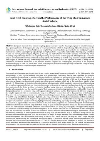
Forthegenerationof anUAVwing model,thedata requiredfortheprofileofthewingistakenfromtheNACAtools. The information available in the form of coordinates is imported to the solid works and the profile is created. The additional features areincorporated into the model to accountfor ribs,spars and skin asshown in Fig 1. The partsthus generated are assembled keeping due connectivity of parts in mind. The whole model of the wing is imported into the Ansysworkbench19.2asastepfileforfurtheranalysis.Thematerialpropertiesrequiredfortheanalysisisimportedfrom the engineering data sources in material library of Ansys Workbench 19.2. The material properties of balsawood, aluminium2024T3,e glass/epoxyandcarbon epoxyareassignedtothevariouspartsofthewing.theimportedgeometry is edited in space claim design modular so that only surfaces are activated for physics to build the layer wise composite structure, other parts needed to be suppressed and saved as a space claim document file which can be used for further discretizationseparatelyinmechanicalmodular.Meshingisperformedontheskinfaceswithafineelementsizebasedon the requirement; the meshed file is transferred to ACP Pre module, where the composite skin is generated in ply wise sequencewithdifferentorientations forthatnumberofpliesarecreatedbydefiningthefibermaterialandthicknessof eachlayer,stackupisbuiltformultifibers,bydefiningtherosettesasetoforientationsetforlayupisprepared,modeling group is created which fully defines the composite structure in terms of number of plies. The space claim document is transferredtomechanicalmodularwheretheskinpartissuppressedforphysicsandinternalstructureconsistingofribs andsparsareactivatedforphysics,thediscretizationofribsandsparsismadeusingafineelementsizeofnotmorethan 5mm
The design of main structural parts such as spars, ribs and skin depend on the selected design parameters. The starting point for the design of a wing box structure is selection of the number of spars. The spars are the main load carrying member of the wing structure. They generally undergo torsional and bending stresses due to aerodynamic loading they are subjected to during the flight. This wing should be consisting of a spar located at 60 % of the chord to supportthesmartcontrolsurfaceswhichhasachordwiselengthof0.4timesthelengthofthechord.Although,thewingof subjectwascomparablysmallonlyonesparcannotsustainthecontinuityofthewing,andhencethereshouldbeanother sparinthewingboxstructure.Thehistoricaldesigndataindicatesthatforatwo sparwingthefront(ormain)sparshould belocatedinbetween12%and17%ofthechordiftherear(orsecondary)sparislocatedat55%to60%ofthechord . The main reason behind this is to make the neutral axis and the shear centers coincide to improve the aero elastic characteristicsofthewing.Thiscombinationofsparsholdstruefortheclosedcross sectionwings.Hence,thedimensions andlocationsofthesparsareselectedasshownin Table1.
International Research Journal of Engineering and Technology (IRJET) e ISSN:2395 0056 Volume: 09 Issue: 06 | June 2022 www.irjet.net p ISSN:2395 0072
S.No Parameters Dimensions
1 Rootchord 1000mm 2 Tipchord 760mm 5 Airfoil(Root) MH114 6 Airfoil(Tip) MH114 7 Frontspar 10mm 8 Rearspar 6x2mm 9 Chordlength(c) 1000mm 10 Spanlength(b) 1800mm 11 ThicknesstoChordRatio,t/c 0.13 12 PlanformareaS 1.75 13 MainSpar 25%,ChordwiseLocationw.r.t.Leading Edge 14 SecondarySpar 60 70%,ChordwiseLocationw.r.t.Leading Edge
Table 1. Dimensions and chord wise locations of the Spars Ribsegmentalnumber Distancebetweentheribs(mm) Distancefromtiprib(mm) Thicknessofrib(mm) 1 0 0 2 2 100 100 2 3 350 450 2 4 350 800 2 5 150 950 2 6 150 1100 2 7 150 1250 2 8 50 1300 2 9 50 1350 2 10 175 1525 2 11 175 1700 2 12 98 1800 2 Thematerialsforthevariouspartsofthewingareasshownin Table 3
Table 2.TheSpanwiseDistancesoftheRibSegmentsfromthetipSectionoftheWinganddistancebetweentheribs
Table 4. Material properties used for a wing model Material E1(Gpa) E2(GPa) V12 G12(GPa) E glass 74 74 022 30 Carbon 230 230 02 10 E glass/epoxy 38.73 6.59 0.29 2.4 Carbon/epoxy 114.14 6.71 0.28 2.2 Balsawood 09 09 031 03435 Al2024T3 731 731 033 266
International Research Journal of Engineering and Technology (IRJET) e ISSN:2395 0056
Volume: 09 Issue: 06 | June 2022 www.irjet.net p ISSN:2395 0072
2.1.1.1. Skin
EachmodelinggroupconsistsoffourpliesofE glassepoxyUDindifferentfiberorientations.Thecompositeisbuiltupin layerwisesequenceandthethicknessofeachlayeris0.25mm.Modellinggroupstackingsequenceis[0/45/45/0].
2.1.1.2. Ribs
Thethicknessofeachribis2mmandhomogeneousE glassepoxyisusedtobuildthemodelinmechanicalmodular,the thicknessisassignedtoeachribmadeof2 Dshellelement.
2.1.1.3.
Thesparsaremadeof1 Dbeamelementsthediameteroffronttubularsparis8mmoverwhichathintubeofthickness 2mmmadeofcarbonepoxyisplacedtostiffenandtoincreasethestrengthpropertiesofspar.
2.1.2. Boundary conditions
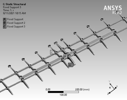
BoundaryconditionsasappliedtothehalfwingmodelareasshowninFig 3andFig4.
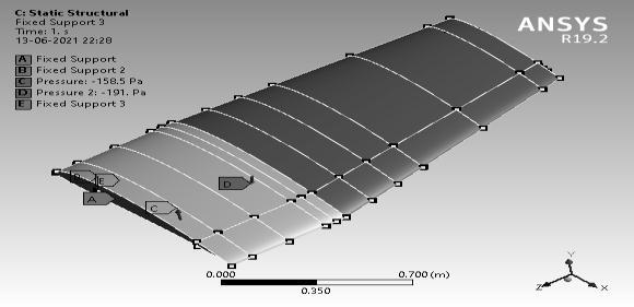
Fig 3. Constrains on the halfwing Fig 4. Pressure loads on the halfwing
2.2.1. Modelling groups in ACP for Full wing
2.2.1.1.
Eachmodellinggroupconsistofeightpliesofcompositeindifferentfiberdirectionorientations.Thecompositeisbuiltup inlayerwisesequenceandthethicknessofeachlayeris0.125mm.Thestackingsequenceadoptedfortheskinstructureis [0/45/45/0]sand[0/30/60/90]s.
2.2.1.2. Ribs
Thethicknessofeachribis5mmandhomogeneousE glassepoxyisusedtobuildthemodelinmechanicalmodular,the thicknessisassignedtoeachribmadeof2 Dshellelement.
2.2.1.3.
Thesparsaremadeof1 D beam elements ofC Section andI Section configuration. Thelengthof sparsalong thespan is 1940mmandheightis6mm(C section),8mm(I section)andthicknessis2mm.
International Research Journal of Engineering and Technology (IRJET) e ISSN:2395 0056
Volume: 09 Issue: 06 | June 2022 www.irjet.net p ISSN:2395 0072
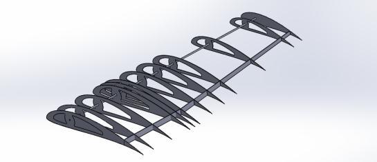
Boundaryconditionsasappliedtothehalfwingmodelareasshowninfig 5andfig6
Fig 5. Constrains on the fullwing
Fig 6. Pressure loads on the fullwing
For validating the methodology adopted in the paper, comparison is made with [ ] available in the literature for the half wingmodelandthesameisaspresentedinTable[5]
Table 5 Validation of results with literature
Parameter Simulationvalues Referencevalues[] location
Totaldeformation 6.52mm 8.6mm Wingtip Max equivalent stress 14.14Mpa 11.9MPa Ribs
Havingvalidatedthehalfwingmodelwiththeliterature,fullwingmodelisanalyzedonsimilarlines. Theresultsofwhich areaspresentedbelow.


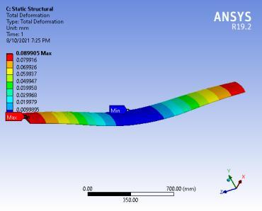
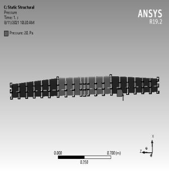
Theanalysisiscarriedoutonaglassepoxyandcarbonepoxymaterialwiththetwostackingsequences.Thisisdonetosee theeffect ofbend twistcouplingon thedeformationperformanceofa compositewing. Twopressuresareappliedtothe wingat20Paand135Pa.TheresultsofthesameareshowninFig7toFig18.
Fig.7.Maximumdeformationof 0.108mmat20Pa,in (0/30/45/60)sGlass/epoxy wing
Fig.8.Maximumdeformationof 0.73mmat135Pa,in (0/30/45/60)sGlass/epoxy wing
Fig.9.Maximumdeformationof 0.09mmat20Pa,in (0/30/60/90)sGlass/epoxy wing
International Research Journal of Engineering and Technology (IRJET) e ISSN:2395 0056
Volume: 09 Issue: 06 | June 2022 www.irjet.net p ISSN:2395 0072
Fig.10.Maximumdeformationof 0.6mmat135Pa,in (0/30/60/90)sGlass/epoxywing
Fig.11.Maximumdeformationof 0.1mmat20Pa,in (0/30/45/60)sCarbon/epoxy wing
Fig.12.Maximumdeformationof 0.66mmat135Pa,in (0/30/45/60)sCarbon/epoxy wing
Fig.13.Maximumdeformationof 0.061mmat20Pa,in (0/30/60/90)sCarbon/epoxy wing
Fig.14.Maximumdeformationof 0.417mmat135Pa,in (0/30/60/90)sCarbon/epoxy wing
Fig.15.Maximumdeformationof 1.71mmat20Pa,inBalsawing
Fig.16.Maximumdeformationof
11.55mmat135Pa,inBalsawing
Fig.17.Maximumdeformationof 0.021mmat20Pa,in Aluminium2024T3wing
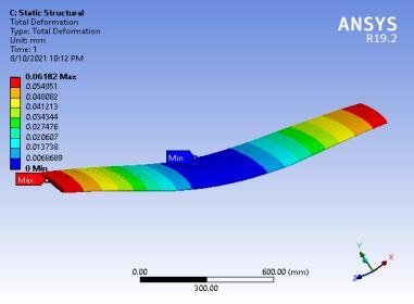
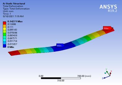
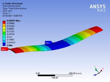
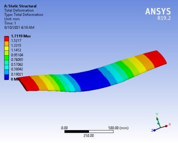
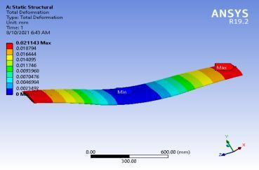
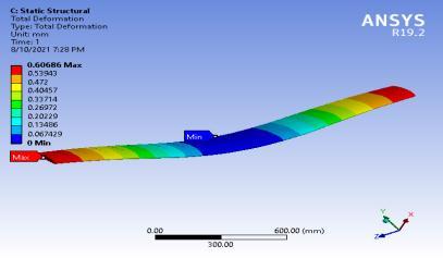

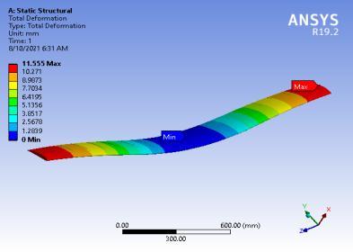
Fig.18.Maximumdeformationof 0.142mmat135Pa,in Aluminium2024T3wing
The layup sequence adopted for the fullwing skin is symmetric which results in coupling matrix B=0. The bend twist couplingcoefficientsD16 andD26 areasareaspresentedinTable[6].
Table 6 Bend-twist coupling coefficients with stacking sequences
Sequence & materials Applied Pressure load[Pa]
Maximum deformatio n(mm)
D16 [ (GPa mm3)] D26 [ (GPa mm3)] Weight (gm)
Glass epoxy (0/30/45/60)s 20 0.108mm 0.34060 0.17568 3056.03
Glass epoxy 135 0.73mm 0.34060 0.17568 3056.03
International Research Journal of Engineering and Technology (IRJET) e ISSN:2395 0056
Volume: 09 Issue: 06 | June 2022 www.irjet.net p ISSN:2395 0072
(0/30/45/60)s
Carbon epoxy (0/30/45/60)s 20 0.1mm 0.11306 0.57831 2276.74
Carbon epoxy (0/30/45/60)s 135 0.66mm 0.11306 0.57831 2276.74
Glass epoxy (0/30/60/90)s 20 0.09mm 0.29397 0.18402 3056.03
Glass epoxy (0/30/60/90)s 135 0.6mm 0.29397 0.18402 3056.03
Carbon epoxy (0/30/60/90)s 20 0.061mm 0.97516 0.60698 2276.74
Carbon epoxy (0/30/60/90)s 135 0.417mm 0.97516 0.60698 2276.74
Balsawood 20 1.71mm 0 0 343.80
Balsawood 135 11.55mm 0 0 343.80
Aluminium2024T3 20 0.021mm 0 0 4232.60
Aluminium2024T3 135 0.142mm 0 0 4232.60
From Table 6 it is evidenced that the stacking sequence of the composite materials plays a vital role in the deformation patternsofa wing. Thecomposite materialscanbestitchedaccordingtothe needs oftheapplicationastheyhaveshape adoptablenatureinherently.Basedontheabovestudy,thefollowingconclusionsarederived.
Inthispaper,thefullwingofanunmannedaerialvehicleisanalyzedattwooperatingconditions,i.e.,at20Paand135 Pa representing the range of operation of UAV. The bend twist coupling coefficients have considerable effect on the deformation pattern produced in UAV which will affect the performance of the same.. The various parameters and their effectonthedeformationpatternofUAVfullwingmadeofbalsawood,Aluminium2024T3,glass epoxyandcarbon epoxy arestudied.
[1] Design and Analysis of Morphing Wing for Unmanned Aerial Vehicles, a thesis Department of MechanicalandIndustrialEngineering,UniversityofToronto,2010.
[2] Balabanov V O, Haftka R T, “Topology optimization of transport wing internal structure”, Journal of Aircraft,Vol.33(1),pp.232 233,1996.
[3] Structuraldesignandanalysisofacompositewingwithhighaspectratio, 8thEuropeanconferencefor aeronauticsandspacesciences(eucass),doi:10.13009/eucass2019 95.
[4] Sziroczak D, Smith H. A review of design issues specific to hypersonic flight vehicles. Progress in AerospaceSciences,2016,84:1 28
[5] Zhang T T, Wang Z G, Huang W, Yan L. A review of parametric approaches specific to aerodynamic designprocess.ActaAstronautica,2018,145:319 331
[6] ZhangT T, Huang W, Wang ZG, YanL. Astudy ofairfoil parameterization, modeling,and optimization based on thecomputtional fluiddynamics method. Journal ofZhejiang University ScienceA (Applied Physics&Engineering),2016,17(8):632 645
[7] CesnikCES,HodgesDH,andPatilMJ.Nonlinearaeroelasticanalysisofaircraftwithhigh aspect ratio wings.NewYork:AIAA,1998,AIAA 98 1995
[8] Eskandary K, Dardel M, Pashaei M H, Moosavi A K. Nonlinear aeroelastic analysis of high aspect ratio wingsinlowsubsonicflow.ActaAstronautica,2012,70:6 22
International Research Journal of Engineering and Technology (IRJET) e ISSN:2395 0056
Volume: 09 Issue: 06 | June 2022 www.irjet.net p ISSN:2395 0072
[9] Duan J B, Zhang Z Y. Aeroelastic stability analysis of aircraft wings with high aspect ratios by transfer functionmethod.InternationalJournalofStructuralStabilityandDynamics,2018,18(12):1850150
[10] GunasekaranM,MukherjeeR.Behaviouroftrailingwing(s)inechelonformationduetowingtwistand aspectratio.AerospaceScienceandTechnology,2017,63:294 303
[11] QiaoSJ,GaoHS,LyuY,HuaL,WangFS.Nonlinearaeroelaticcharacteristicsanalysisofcompositewing with high aspect ratio based on co rorational method. Journal of Fluids and Structures, 2018, 82: 619 637
[12] QiaoSJ,GaoHS,LyuY,HuaL,WangFS.Nonlinearaeroelaticcharacteristicsanalysisofcompositewing with high aspect ratio based on co rorational method. Journal of Fluids and Structures, 2018, 82: 619 637
[13] TahirTurgut,“ManufacturingandstructuralanalysisofalightweightsandwichcompositeUAVwing”,A thesis,theschoolofnaturalandappliedsciences,Middleeasttechnicaluniversity,2007.
[14] S. Solomon Raj and Dr. P. Ravinder Reddy., “Utilization of bend twist coupling to improve the performance of hybrid marine composite propeller”, International Journal of Mechanical Engineering andTechnology.e ISSN:0976 6359,p ISSN:09766340Vol.9,Issue.3,pp.443 449,2018
[15] S.SolomonRajandDr.P.RavinderReddy.,“Bend Twistcouplinganditseffectoncavitationinceptionof composite marine propeller”,International Journal of Mechanical Engineering and Technology. e ISSN: 0976 6359,p ISSN:09766340Vol.5,Issue.9,pp.306 314.2014
[16] S. Solomon Raj and Dr. P. Ravinder Reddy., “Effect of stacking sequence on the performance of marine propeller”,InternationalJournalofAppliedEngineeringResearch,ISSN:0973 4562,Vol.6,No.20,2011, pp.2367 2374