Volume: 09 Issue: 06 | June 2022 www.irjet.net p ISSN:2395 0072

Volume: 09 Issue: 06 | June 2022 www.irjet.net p ISSN:2395 0072

Ayush Pandey1 , Kumar Vanshaj2 , Gaurav Singh3 , Saurabh Yadav4 , J.B. Srivastav5
1,3,4 B.tech Final Year Civil Engineering Department, Institute of Engineering & Technology, Lucknow. 2 Assistant Professor, Civil Engineering Department, Institute of Engineering & Technology, Lucknow 5 Professor, Civil Engineering Department, Institute of Engineering & Technology, Lucknow ***
Abstract India’stransportsectorislargeanddiverse;itcaterstotheneedsof1.1billionpeople.Roadsarethedominant mode of transportation in India today. They carry almost 85percent ofthecountry’s passenger traffic andmorethan 60 percentofitsfreight.
FlexilepavementsarebyfarconsistsmostoftheportionofIndianroadsowingtothefactthattheyarelessexpensive,easy formaintenanceandrepair,lesstechnicalityinvolveetc.
Flexible pavements are so named because the total pavement structure deflects, or flexes, under loading. A flexible pavementstructure is typically composed of several layers of materials. Each layer receives loads from the above layer, spreadsthem out,andpassesontheseloadstothenextlayerbelow.Thus,the stresseswillbereduced,whicharemaximum at the top layer and minimum on the top of subgrade. In order to take maximum advantage of this property, layers are usuallyarrangedintheorderofdescendingloadbearingcapacitywiththehighestloadbearingcapacitymaterial(andmost expensive)onthetopandthelowestloadbearingcapacitymaterial(andleastexpensive)onthebottom.
Thetypeofhighwaypavementthattransmitstheimposedwheelloadtotheunderlyinglayersbyagrain to graintransfer mechanismandiscommonlyconstructedutilizingbitumen&aggregatesisknownasflexiblepavement.
Volume: 09 Issue: 06 | June 2022 www.irjet.net p ISSN:2395 0072
Flexible pavement can be defined as the one consistingof a mixture of asphaltic or bituminous material and aggregates placedonabedofcompactedgranularmaterialofappropriatequalityinlayersoverthesubgrade.Waterboundmacadam roadsandstabilizedsoilroadswithorwithoutasphaltictoppingsareexamplesofflexiblepavements
Thesepavementshavenegligibleflexuralstrengththereforeundergoesdeformationundertheactionofloads.
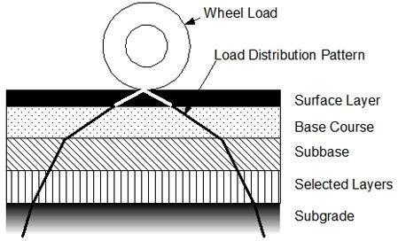
Load from standard vehicles acts on the wearing coarseand it gets dispersed with depth in the base, sub base, and subgradecoarse.Astheloadisappliedontop surfacehencetrafficloadingishighestontopsurfaceasaresultstiffnessof differentlayersdecreasesfromtoptobottom.Buttheselayersalsoareequallyimportantinpavementcomposition.
Fromthepasttherearevariousmethodsforthedesignofflexiblepavement,butthemostadoptablemethodisCBRmethod becauseitisalsosuggestedbyourIRC:37.
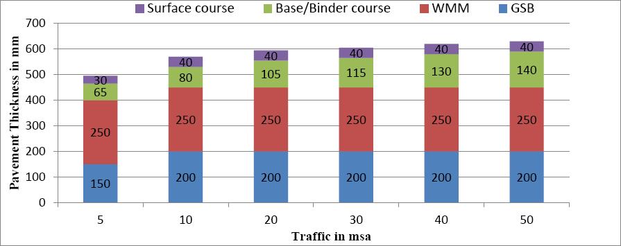
WiththehelpofCBRvalueandtrafficdata,wecanselectadepthfromcataloguegivenbyIRC:37.
The depth suggested by IRC sometimes comes out tobe over safe and uneconomical, therefore revision in depth may be needed. This revision can be done through IIT PAVE software. This software computes actual strain that acts on the pavementatrequiredsectionsduetosuperimposedload.
IITPAVEsoftwarehasbeendevelopedfortheanalysisoflinearelasticlayeredpavement system.Thestresses,strainsand defections caused at different locations in a pavement by a uniformly distributed single load applied over a circular contactareaatthesurfaceofpavementcanbecomputedusingthissoftware.Theeffectofadditionalloads (whichshould alsobeuniformlydistributedloadsovercircularcontactareas)wasconsideredusingsuperpositionprinciple.
Punmiaet. al (2005)have reported stressesinhomogeneousmass;elasticdeformationundercircularloadandBurmister analysis for flexible pavement. Charts for vertical deflections have been developed. The design curves by Group Index MethodandCaliforniaBearingRatioMethodhavebeendeveloped.InGroupIndexMethod,thecurvesareplottedbetween GroupIndexandthickness. In California Bearing Ratio Method curves areplotted betweenthicknessof constructionand CaliforniaBearingRatio.
Subagio et.al (2005) discusses a case study for multilayer pavement structural analysis using methods of equivalent thickness. An approximate method has been developed to calculate stresses and strains in multilayer pavement systems by transforming this structure into an equivalent one layer system with equivalent thicknesses of one elastic modulus. This concept is known as themethod of equivalent thickness which assumes that the stresses and strains below alayer dependonthestiffnessofthatlayer.
Khan(1998)elaboratestheGroupIndex MethodandCaliforniaBearingRatioMethodfordesignofflexiblepavements.In GroupIndexMethodthethicknessisobtainedbyfirstdeterminingtheGroupIndexofsoil.Thecurvesareplottedbetween GroupIndexofsubgradeandthicknessforvarioustrafficconditions.
International Research Journal of Engineering and Technology (IRJET) e ISSN:2395 0056
Volume: 09 Issue: 06 | June 2022 www.irjet.net p ISSN:2395 0072
StructuralAnalysisoftheselectedpavementstructure:
ThisistobedonebyrunningtheIITPAVEsoftwareoranyotherlinearelasticlayer programmeusingasinputsthelayer thicknesses,thelayermoduli,thelayer
Poisson’s ratio values, the standard axle load of 80 kN distributed on four wheels (20 kN on each wheel), and a tyre pressureas0.56MPa.Forcarryingoutfatiguedamageanalysisofcementtreatedbases,theaxleloadunderconsideration and a contact pressure of 0.80 MPa will be considered. The program will output the stresses, strains and deflections at selectedcritical locationsinthe pavement from which the values of critical mechanistic parameters can be identified for design.AsoftcopyoftheIITPAVEsoftwareisattachedaspartofthisdocument.DetailsaboutIITPAVEandinstructionsfor itsinstallationandusearegiveninAnnex I.
Thesingleverticalloadappliedatthesurfaceisdescribedintermsof(anyone)
contactpressureandradiusofcontactarea Wheelloadandcontactpressure Wheelloadandradiusofcontactarea.
ForIITPAVE,wheelloadandcontactpressurearetheloadinputs.Thepavementinputsrequiredaretheelasticproperties (elastic/resilient moduli and Poisson’s ratiovalues of all the pavement layers) and the thicknesses of all the layers (excludingsubgrade).IITPAVEsoftware,initscurrentversion,canbeused toanalysepavementswithamaximumoften layersincludingthesubgrade.Ifthenumber oflayersinthepavementismorethanten, differentlayersofsimilarnature (e.g.,granular,bituminous)canbecombinedandconsideredasonelayer.Cylindrical coordinatesystemisfollowedinthe program.Thus,thelocationofanyelementinthepavementisdefinedby(a)depthofthelocationoftheelementfromthe surface of the pavement and the radial distance of the element measured from the vertical axis of symmetry (along the centreofthecircularcontactareaofonewheelload).
TodesigntheflexiblepavementbyCBRmethodusingIRC37 2018.
ToanalyzethedepthusingIITpavesoftware.
TodeterminestrainsatcriticalpointsusingIITpavesoftware.
Tofindtheoptimaldesignofflexiblepavementusingvariousmethod.
Cbrtestperformedonthesoilsamplecollectedfromsite.ThevalueofCBRcomesouttobe5.3%.
TrafficdataiscomputedfromtheformulagivenbyIRC37Ndes=365*[(1+r)n 1]*A*D*F/r Trafficfortheroadcomesouttobe4.3MSA 3. Selection of trial depth from IRC:37 2012
International Research Journal of Engineering and Technology (IRJET) e ISSN:2395 0056
Volume: 09 Issue: 06 | June 2022 www.irjet.net p ISSN:2395 0072
Figure4.ThicknessofDifferentlayercorresponding5%CBRWehaveselected1st depthastrialonsoftware
4. Calculation of Resilient Modulus (M):
Mbitumen =700MPa(forVG30@30oC) [IRC:37 2018table7.1]
Msubgrade=17.6*(CBR)0.64forCBR>5% (Msubgrade=MRSUPPORT) =17.6*(5.3)0.64=51.17MPa
MRGRAN=0.2(h)0.45*MRSUPPORT=0.2*(400)0.45*51.17=151.7MPa
5. Calculation of Maximum allowable Strain for Rutting& Fatigue:
NR=Nf =Ndes=4.34*106
ForRutting, NR =4.1656x10 08 [1/εv]4.5337 (for80%reliability) =4.34*106
Implies, εvmax =809.25*10 6
ForFatigue, Nf=1.6064*C*10 04[1/εt]3.89*[1/MRm]0.854(for80 %reliability) =4.34*106 Implies, εtmax =536*10 6
6. Now, substituted the above values i.e., (a)ThicknessofLayers; (b)ResilientModulus; (c)Poisson’sRatio(0.35foreverylayer); (d)Wheelload(standardloadof20kN); (e)Tyrepressure(standardpressureforGSBi.e.,0.56)and
© 2022, IRJET | Impact Factor value: 7.529 | ISO 9001:2008 Certified Journal | Page281
International Research Journal of Engineering and Technology (IRJET) e ISSN:2395 0056
Volume: 09 Issue: 06 | June 2022 www.irjet.net p ISSN:2395 0072
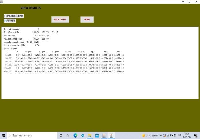
(f)Analysis point details (respective depths and radial distance) in the software (IITPAVE) and obtained the values of εv andεtasfollowing:
εt@95mm=410.05*10 6<εtmax εv@495mm=157.77*10 6 <εvmax
Figure5.Strainsfromtrial1
Furtherchangingthethicknessofthelayersandcalculatingvaluesofεvandεtagain.
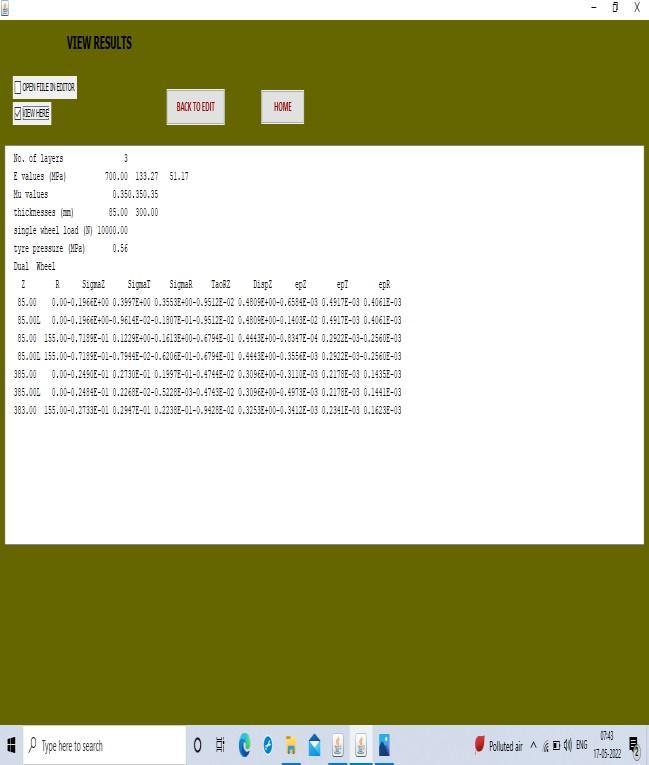
ThicknessofLayer1=85mmThicknessofLayer2=300mm MRGRAN=0.2(h)0.45*MRSUPPORT=0.2*(300)0.45*51.17=133.27MPa
SubstitutedthisvalueofMRGRANwiththepreviousvalueandobtainedthevaluesofεvandεtasfollowing:
εt@85mm=394.16*10 6<εtmax εv@385mm=479.3*10 6 <εvmax
Figure6.StrainsfromTrial2
Volume: 09 Issue: 06 | June 2022 www.irjet.net p ISSN:2395 0072
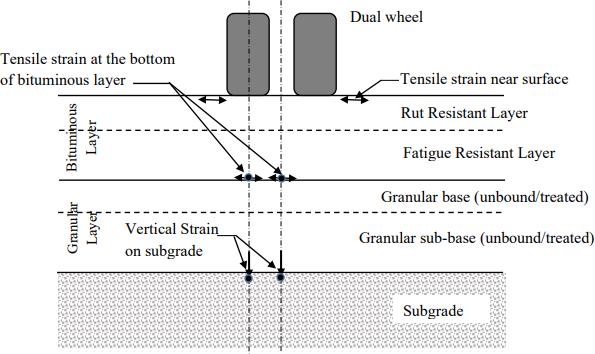
Figure7.Compressiveandtensilestrainsatdifferentlayers
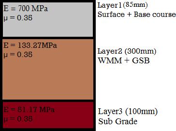
HenceourFinalPavementwill
Figure8.FinalThicknessofDifferentLayers
1. ConsideringthefatiguecriteriamentionedinIRC:37 2018,wehaveobtainedcertainvalueoftensilestrain.Thisvalue oftensilestrainisthemaximumvalueoftensilestrainthatcanbeallowedonthepavement.
2. ConsideringtheruttingcriteriamentionedinIRC;37 2018,wehaveobtainedcertainvalueofcompressivestrain.This valueofcompressivestrainisthemaximumvalueofcompressivestrainthatcanbeallowedonthepavement.
3. Thetensileandcompressivestrainsobtainedfromthesoftwareismuchlesserthenthetensileandcompressivestrain obtainedbyusingtheformulasmentionedintheIRC:37 2018.
4. So, we can reduce the thickness of the differentlayers by some amount so that the difference between the strains obtainedbybothethemethodisreduced.
Thevaluesofstrainsarementioned below:
1. εtmax =536*10 6
2. εvmax =809.25*10 6
3. εt@95mm=410.05*10 6 <εtmax
International Research Journal of Engineering and Technology (IRJET) e ISSN:2395 0056
4. εv@495mm=157.77*10 6 <εvmax
Thevaluesofthethicknessofdifferentlayersarementionedbelow:
S. No Layers Modulus (in MPa) Poisson’s Ratio Thickness (in mm )
1. BituminousLayer 700 0.35 85
2. WMM+GSB 133.27 0.35 300
3. Subgrade 51.17 0.35 100
1. From the values of the maximum tensile strain and maximum compressive strain obtained fromthe formuls mentioned in the IRC:37 2018 ( the manual method ) and the values of the tensile and compressive straims obtained by putting thevalues of thickness of different lyers, we can conclude that we can further reduce the thicknessofeachlayerbysomeamountsothatthestraindifferencesobtainedbybothmethodisreduced.
2. Thisdifferencesuggestsusthatevenafterthereductionofthethicknessofeachlayerswecanstillconstructsafe pavementwiththestrainwithinthesafelimits.
3. Now,thereductionofdifferentlayerconcludesthatwecanstillmakethesafeandproperfunctionablepavement withreducedamountoftheMaterialused. Thusthereductionofthematerialcanbringustotheconstructionofmoreeconomicpavement.
1. https://www.researchgate.net/publication/350212551_A_Review_of_Software_in_Flexible_Pavement_Design
2. https://www.civilax.com/flexible pavement design iit pave pavement design software/#:~:text=IIT%20Pave%20is%20a%20software,made%20available%20to%20the%20public
3. https://www.nbmcw.com/article report/infrastructure construction/roads and pavements/flexible pavement versus rigid pavement.html#:~:text=Flexible%20pavements%20i n%20India%20are,a%20period%20of%2015%20year s
4. IRC:37 (2012) For the manual approach i.e., the formula used for the calcultion of maximum allowable strains, consideringtheruttingandfatiguecriteria.
5. IRC:37(2018) For the guidelines about the software approach i.e., how to use IITPAVE software for the constructionofflexiblepavement.
6. Khan,I.H.(1998)ATextbookofGeotechnicalEngineering,PenticeHallofIndiaPrivateLimited,NewDelhi
7. Arora,K.R.(2003)SoilmechanicsandFoundationEngineering,StandardPublishersDistributors,Delhi
8. Das, A. (2008) Reliability Considerations of BituminousPavement Design by Mechanistic Empirical Approach, theInternationalJournalofPavementEngineering,Vol.9,No.1,pp.19 31.
9. Subagio, B. Cahyanto, H., Rahman, A. and Mardiyah, S.(2005) Multilayer Pavement Structural Analysis Using Method of Equivalent Thickness, Case Study: Jakarta CikampeckTollRoad,JournaloftheEasternAsiaSocietyfor TransportationStudies,Vol.6,pp.55 65.
10. layersofflexiblepavement Bingimages
11. layersofflexiblepavement Bingimages
Volume: 09 Issue: 06 | June 2022 www.irjet.net p ISSN:2395 0072 © 2022, IRJET | Impact Factor value: 7.529 | ISO 9001:2008 Certified Journal | Page284