International Research Journal of Engineering and Technology (IRJET) e ISSN: 2395 0056
Volume: 09 Issue: 05 | May 2022 www.irjet.net p ISSN: 2395 0072
International Research Journal of Engineering and Technology (IRJET) e ISSN: 2395 0056
Volume: 09 Issue: 05 | May 2022 www.irjet.net p ISSN: 2395 0072
Krutangkumar Sureshbhai Patel1, Svadas Hemang Jayeshbhai2, Trivedi Meet Paresh3, Meet Mukeshbhai Patel4
1Automobile Engineering, Pass Out from SAL Institute of Technology and Engineering Research, Gujarat, India 2Mechanical Engineer, Pass Out from Indus University, Gujarat, India 3Mechanical Engineer, Pass Out from L. J. Institute of Engineering and Technology, Gujarat, India 4UG Student of Automobile Engineering, Indus University, Gujarat, India ***
Abstract Brake system is vital for stopping or decreasing moving vehicle’s speed. Hydraulic brake system is provided for All Terrain Vehicle that includes optimization of master cylinder and fixed caliper inputted in self customized outboard wheel. In the inboard brake system the brake discs are rigidly mounted on brake shaft or on drive shaft. The main advantage of using this braking technology is reduction of unsprung weight which improves handling and ride. The primary aim of this project is to show the utility and performance of the disc brakes with rear inboard braking system and to perform CAE analysis of brake discs used in braking system.
Key Words: Brakes,DiscBrakes,InboardBrake,Hydraulic Brakes,BrakesinATV.
AnATVistheshort formofAllTerrainVehicle,whichruns on as it name suggests all rough terrains. ATV consists of threeorfournonlinearalignedwheels.Thetiresarekeptin low air pressure to ensure optimum grip and shock absorbingcapabilitiesofthevehicleeveninoffroads.
ATV comes in a single seater or a driver and a passenger seatervariants.SomeATValsohaveacagearoundthedriver areawhichensuresdriversafetyinthecaseofarollover.
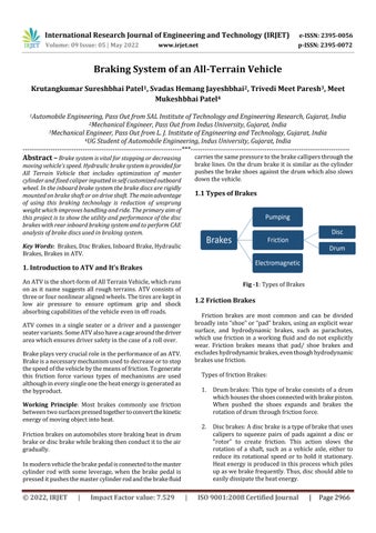
BrakeplaysverycrucialroleintheperformanceofanATV. Brakeisanecessarymechanismusedtodecreaseortostop thespeedofthevehiclebythemeansoffriction.Togenerate this friction force various types of mechanisms are used althoughineverysingleonetheheatenergyisgeneratedas thebyproduct.
Working Principle: Most brakes commonly use friction betweentwosurfacespressedtogethertoconvertthekinetic energyofmovingobjectintoheat.
Frictionbrakesonautomobilesstorebrakingheatindrum brakeordiscbrakewhilebrakingthenconductittotheair gradually.
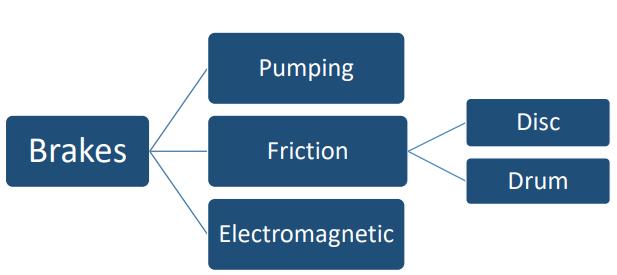
Inmodernvehiclethebrakepedalisconnectedtothemaster cylinder rod with some leverage, when the brake pedal is presseditpushesthemastercylinderrodandthebrakefluid
carriesthesamepressuretothebrakecallipersthroughthe brakelines.Onthedrumbrakeitissimilarasthecylinder pushesthebrakeshoesagainstthedrumwhichalsoslows downthevehicle.
Friction brakes are most common and can be divided broadlyinto“shoe”or“pad”brakes,usinganexplicitwear surface, and hydrodynamic brakes, such as parachutes, which use friction in a working fluid and do not explicitly wear. Friction brakes means that pad/ shoe brakes and excludeshydrodynamicbrakes,eventhoughhydrodynamic brakesusefriction.
1. Drumbrakes:Thistypeofbrakeconsistsofadrum whichhousestheshoesconnectedwithbrakepiston. When pushed the shoes expands and brakes the rotationofdrumthroughfrictionforce.
2. Discbrakes:Adiscbrakeisatypeofbrakethatuses calipers to squeeze pairs of pads against a disc or "rotor” to create friction. This action slows the rotation of a shaft, such as a vehicle axle, either to reduce its rotational speed or to hold it stationary. Heatenergyisproducedinthisprocesswhichpiles upaswebrakefrequently.Thus,discshouldableto easilydissipatetheheatenergy.
2022, IRJET | Impact Factor value: 7.529 | ISO 9001:2008 Certified Journal

International Research Journal of Engineering and Technology (IRJET) e ISSN: 2395 0056
Volume: 09 Issue: 05 | May 2022 www.irjet.net p ISSN: 2395 0072
3.2.1 Statics:
Weightofthevehicle(W)=mxg=220x9.81=2158.2N Wheelbase(L)=25.4x54.14=1375.156mm
Longitudinal distance of C.G. from front axle (L1) = 25.4 x 34.95=877.75mm
Longitudinal distance of C.G. from rear axle (L2) = 25.4 x 19.19=487.42mm
ADiscbrakeisatypeofbrakethatusescaliperstosqueeze pairs of pads against a brake disc to create friction. This actionslowstherotationofwheel.Hydraulicdiscbrakesare widelyusedformofdiscbrakeformotorvehicles.
Main components of Disc Brake:
Brake disc: It is the rotating part of a wheel’s disc brake assembly,thebrakepadsapplyfrictionforceonthispart
Brake Caliper: It is the assembly which houses the brake padsandthepistons.
Aim of the project: Theprimaryaimoftheprojectistoshow theutilityandtheperformanceofthebrakesystemofanATV with rear inboard braking systemand to perform the CAE analysisofbrakediscsusedinbrakingsystem.
Problem specification:Outboardconfigurationofbrakingis alsoaveryefficienttechniquebutthedisadvantagesofitare the brake lines, calipers, brake disc are exposed while mountingitinthisconfigurationwhichleadtodamagefrom obstacles such as rocks and often debris. It also required more space for the mounting of caliper’s and ultimately it overall required more space for designing of wheel hub assemblies.
TheBrakingsystemusesafront/rearsplitbrakingcircuit. Onemastercylinderhavingborediameterof19.05mmis used.Twofixedsinglepistoncalipersonfrontwheelsand onedualpistonfloatingcaliperontherearinboarddisc is used.Borediameteroffrontandrearbrakecaliperis30mm and25.4mmrespectively.Thebrakecalipersareconnected tomastercylinderthroughsemimetallicbrakelineswhich ensuresnoleakageofbrakefluid.
Theweightonfrontandrearaxleinstaticconditioncanbe calculatedas, Frontaxlestaticload(w1)=WxL2/L =2158.2x487.42/1375.156 =764.96N
Rearaxlestaticload(w2)=WxL1/L =2158.2x877.75/1375.156 =1377.56N
3.2.2 Dynamics:
HeightofC.G.(h)=25.4x22.46 =570.49mm
Co efficientoffrictionbetweenroadandtires=0.6
Radiusoftire=(23/2)x25.4 =292.21mm
Frictionalforceonvehicle(Ff)=µN=µmg=0.6×2158.2 =1294.92N
InertiaForceduetodeceleration(Fi)=mxd=220×d Ff=Fi 1294.92=220xd d=5.887m/s2 d/g=0.6
Front axle dynamic load = wfd = {W( L2 + (d/g)h)}/L = {2158.2(0.487+0.6x.570}/1.375=1302.17N
Rear axle dynamic load = wrd = {W( L1 + (d/g)h)}/L = {2158.2(0.877+0.6x.570)}/1.375=1914.76N
Amountoffrictionaltorquerequiredonthewheelstostop thevehicle.
Frictionaltorquerequiredatfrontwheels=Tf=µrxwfdxR =.6x1302.17x.292=228.14N-m
Frictionaltorquerequiredatrearwheels=Tr=µrxwrdxR =.6x1914.76x.292=335.36N-m
Areaofmastercylinderbore(Amc)=∏4d2=∏4(19.05)2 =285.02mm2
Areaofpistoncylinderbore
International Research Journal of Engineering and Technology (IRJET) e ISSN: 2395 0056
Volume: 09 Issue: 05 | May 2022 www.irjet.net p ISSN: 2395 0072
For front caliper (Vespa) (Afc) = ∏ 4 df 2 = ∏ 4 (30)2 = 706.85mm2
Forrearcaliper(Pulsar150)(Arc)=2x∏4dr2=2x∏4 (25.4)2=1013.41mm2
PedalRatio=5:1
PedalForceappliedbydriver=350N ForceatBalancebar=350×5=1750N
For Front Wheels:
Actuationforceatmastercylinderforfrontbrakes=Forceat balancebarx0.5=1750x0.5=875N
Pressuregeneratedinsidemastercylinder=Force/Amc= 875/0.000285=3.07Mpa
Force applied by caliper = pressure x Afc = 3.07 x 106 x 0.000706=2167.42N
Clampingforce=2x2167.42=4334.84N
Friction force applied by brake pad on rotor = Clamping forcexµd=4334.84x0.4=1733.93N
Brakingtorque=FrictionforcexEffectiveradiusofbrake disc114.07=1733.93xRdf Rdf=65.78mm
Discouterradius=(66+15)=81mm Finaldiscdiameter=81x2=162mm
For rear axle with inboard brakes:
Actuationforceatmastercylinderforrearbrakes=1750x 0.5=875N
Pressuregeneratedinsidemastercylinder=Force/Area= 875/0.000285=3.07Mpa
Forceappliedbycaliper=ForcexArc=3.07x106x1013.41 x106=3111.16N
Clampingforce=2x3111.16=6222.32N
Frictionforceappliedbybrakepadonbrakedisc=Clamping forcexµd=6222.32x0.4=2488.92N
Brakingtorque=Frictionalforcexeffectiveradiusofbrake disc167.68=2488.92xRdr
Rdr=67.37mm
Discouterradius=(67.37+15)=82.37mm Finaldiscdiameter=2x82.37=165mm
Kinetic energy developed during braking:
KE=½mv²
KE=½x300x(11.11)²
KE=13577.53J
TotalBrakingenergy/Heatrequiredforthevehicleisequal tothetotalkineticenergygeneratedbythevehicle, Thus(Qg)=13577.53J
Since assumption of 50 50 bias is made, this heat will be equally distributed in 4 wheels of the car, thus equally distributedin4brakediscs.
So,heatgeneratedin1brakedisc,Qg=3394.38
Now, the stopping time of the vehicle will be velocity/deceleration. t=V/a t=11.11/5.887=1.88s
Hencepowergeneratedinonebrakedisc, P=Qg/t=3394.38/1.88=1805.52Watt
Hencewecancalculatetheheatflux
Heatfluxforfrontbrakedisc=4xP/3.14x(Dₒ ² Di²)=4x 1805.52/3.14x(0.1632 0.0552)=97690.51W/m²
Heatfluxforrearbrakedisc=4xP/3.14x(Dₒ ² Di²)=4x 1805.52/3.14x(0.1702 0.0702)=95834.39W/m²
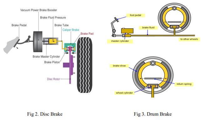
3.3 Comparison of previous year’s OEM brake disc & present year’s brake discs:
Table1:DifferencebetweentheOEMbrakediscandour brakedisc
4. Material selection of brake disc:
Forcars,themostcommonlyuseddiscmaterialiscastiron, becauseofitsgoodfrictionproperties,lowcost,relativeease ofmanufactureandthermalstability.
Becauseofthesignificantreductionpossibleintheweightof thedisc,Aluminiummetalmatrixcomposites(AMMC)with
2022, IRJET | Impact Factor value: 7.529 | ISO 9001:2008 Certified Journal
International Research Journal of Engineering and Technology (IRJET) e ISSN: 2395 0056
Volume: 09 Issue: 05 | May 2022 www.irjet.net p ISSN: 2395 0072
SiCreinforcementisconsideredasapossiblealternativeto castirondiscsforcars.Although,Castironischeaperthenit, and is yet to be produced reliably in a large scale in mass production.
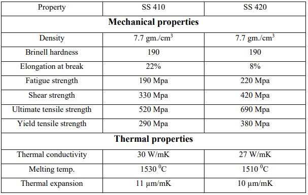
Formotorcycles,stainlesssteel(SS410&420)isthemost commonly used material. They provide good resistance againstcorrosion,andcanbeinductionhardenedtoincrease thehardnessforprovidinggoodwearresistance.
Racingmotorcyclesusecarbonfibrediscs.But,becausethis materialrequireshightemperaturetoachievethedesired frictionlevel,itcannotbeusedfornormalmotorcycles.
Table2:ComparisonbetweenSS410andSS420
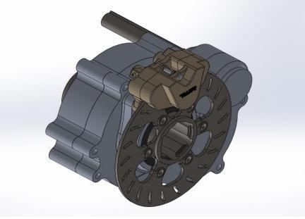
Front Assembly:
Fig 4:BrakediscandCalipermountiononKnuckel
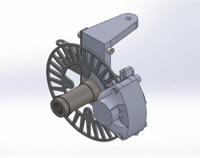
Fig 5:Brakediscandcalipermountedongearboxoutput shaft
Outboard configuration of braking is also a very efficient technique but the disadvantages of it are the brake lines, calipers, brake disc are exposed while mounting it in this configurationwhichleadtodamagefromobstaclessuchas rocksandoftendebris.Italsorequiredmorespaceforthe mountingofcaliper’sandultimatelyitoverallrequiredmore space for designing of wheel hub assemblies. While in inboardconfigurationthebrakediscismountedonthefinal drive.Brakediscsaremounteddirectlyontheoutputshaft or the brake shaft rather than the wheel hub, this configurationiscalledInboardbrakesystem.Hencebyusing inboard braking configuration with proper design calculationandmodellingofbrakediscwecanavoidabove problems of outboard configuration. As inboard configurationisvery effectiveitreducestheweightofthe brakingsystemandreducesmanufacturingcost&time.The mainadvantageofusingthisbrakingtechnologyisreduction ofunsprungweightwhichimproveshandlingandride
[1] Aman sharma, Prakhar Amrute, Suryakant Singh Thakur, Jatin Shrivastav, Design, Analysis and fabricationofbrakingsystemwithrearinboardbrakes, IRJET,2018.
[2] Richard Gardner, Disc brake caliper and mounting structure,US3910385A,18/04/1974.
[3] Tatsuya Matsuura, Brake system layout for ATV, US6478103B1,27/04/1999.
[4] Hitoshi Takeuchi, Brake disc, US7575107B2, 10/12/2007.
2022, IRJET | Impact Factor value: 7.529 | ISO 9001:2008 Certified Journal |
International Research Journal of Engineering and Technology (IRJET) e ISSN: 2395 0056
Volume: 09 Issue: 05 | May 2022 www.irjet.net p ISSN: 2395 0072
Mr. Krutangkumar Sureshbhai Patel, Completed Bachelor’sdegreeinAutomobileEngineering,SAL InstituteofTechnologyandEngineeringResearch, GujaratTechnologicalUniversity.
Svadas Hemang Jayeshbhai, was a student of department of mechanical engineering, Indus institute of technology and engineering, Indus University.

TrivediMeetParesh,wasastudentofdepartment of mechanical engineering, L. J. institute of engineeringandtechnology,GujaratTechnological University.


Mr.MeetMukeshbhaiPatel,completedBachelor’s Degree in automobile engineering at Indus institute of technology and engineering, Indus University.
2022, IRJET | Impact Factor value: 7.529 | ISO 9001:2008 Certified Journal