A Review on Offshore Wind Turbine Foundations
Aleeda Shaju1Mtech Student, Dept. of Civil Engineering, St. Joseph’s College of Engineering and Technology, Palai Assistant Professor, Dept. of Civil Engineering, St. Joseph’s College of Engineering and Technology,
Abstract wind power are fastest growing popular, sustainable and renewable energy resource that has lesser shock on the surroundings than burning conventional fuels. Offshore winds are clean and sustainable renewable energy resource with great latent value for the energy trade in the circumstance of a low carbon world. The rapid expansion of offshore wind power depends on a excellent understanding of the practical issues associated with offshore wind turbines, which drive current investigate and improvement programs. The foundation of an offshore wind turbine is one of the most challenging tasks in the design of an offshore wind turbine. This article provides an indication of the types of offshore wind turbine foundation, important design consideration, effect of vertical and horizontal loads etc.
Key Words: Wind Power, Renewable Energy, Offshore Wind Turbines, Offshore Wind Turbine Foundation, Design Consideration

1.INTRODUCTION
Renewable energy source has become increasingly important over recent years as a means of achieving international goal for reduced greenhouse gas emissions whileensuringenergysecurity.Sunistheprimarysourceof renewable energy and wind is a secondary source of renewableenergydependentonthesun.Thewindvelocity isinfluencebytopographicalfeaturesandrevolutionofthe earth.Bhattacharya et.al[6]studied that Offshorewind farmsareconsidermostreliableenergysourceduetosome reasons:
(1)Theaveragewindspeedishigherinoffshoreanditis consistentthroughouttheyear
(2) Offshore wind turbine have minimum vibration impactandnoiseimpactonhumancomparewithonshore windturbine
(3)Byuseofhybridsystemscurrentandwaveenergies canbeharvestalongwithwindfarms
Offshore wind farms are popular in United Kingdom, EuropeandGermany.Theworld'sfirstseawardwindfarm was built in Denmark. Offshore wind farm industry is expectedtogrowoverthenextdecades.Thefuturescopeof offshore wind farms are wide by considering the lower airstreamshear,higherenergydensity,lowerinstability,and lowcivilcomplaintscontrastwithinlandwindfarms.Total
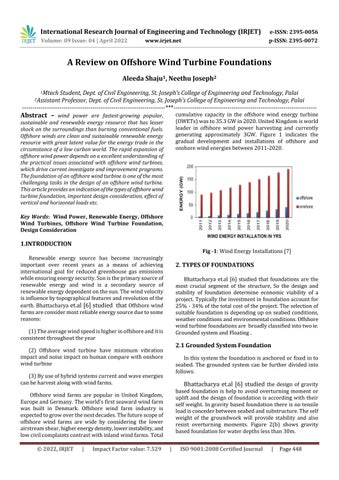
cumulative capacity in the offshore wind energy turbine (OWETs)wasto35.3GWin2020.UnitedKingdomisworld leader in offshore wind power harvesting and currently generating approximately 3GW. Figure 1 indicates the gradual development and installations of offshore and onshorewindenergiesbetween2011 2020.
Fig 1:WindEnergyInstallations[7]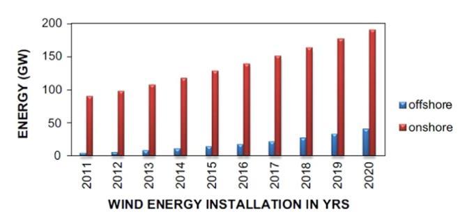
2. TYPES OF FOUNDATIONS
Bhattacharya et.al [6] studied that foundations are the most crucial segment of the structure, So the design and stability of foundation determine economic viability of a project.Typicallytheinvestmentinfoundationaccountfor 25% 34%ofthetotalcostoftheproject.Theselectionof suitable foundation is depending up on seabed conditions, weatherconditionsandenvironmentalconditions.Offshore windturbinefoundationsare broadlyclassifiedintotwoie. GroundedsystemandFloating
2.1 Grounded System Foundation
Inthissystemthefoundationisanchoredorfixedinto seabed. The grounded system can be further divided into follows:
Bhattacharya et.al [6] studied the design of gravity based foundation is help to avoid overturning moment or upliftandthedesignoffoundationisaccording withtheir selfweight.Ingravitybasedfoundationthereisnotensile loadisconcederbetweenseabedandsubstructure.Theself weight of the groundwork will provide stability and also resist overturning moments. Figure 2(b) shows gravity basedfoundationforwaterdepthslessthan30m.
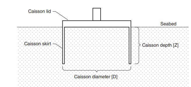
Suction caissons be also known as suction bucket. The suctionbuckethavelongskirtsaroundtheperimeter.The diametertolengthratioofthesuctionbucketisaroundone. Thecomponentsofcaissonbucketarerigidcircularlidand slendertubularskirt.Thesefoundationsmainlyusedinoils andgasmanufactureplatforms. Figure2(a)showssuction bucketforwaterdepthslessthan30.
Ma et.al [2] studied that Monopole is a single large diametersteeltubewithopenends.Typicallythediameter ofthemonopolevariesfrom4to6mandslendernessratio isintherangeof4to8.Monopileisconnectedtotransition piece i.e. a steel tube which support boat landings and ladders.Figure2(c)showsmonopilefoundation.Monopile foundation is the simplest form of grounded system foundation.Theinstallationprocessofmonopilefoundation isverysimplethanothertypes.Hermanset.al[15]studied thatTypicalmonopilefoundationshave thediameterinthe range of3to8meterandtheeconomical waterdepthsare consideredas 20 40meter
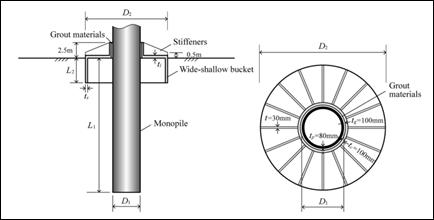
Thomsenet.al[17]studiedthatThejaacketfoundation Figure2(e)ismanufacturedupofsteeltubularelementsthat arenormallyassembledonlandinadvancebywelding.The jaacketisthentransportedtolocation,anderectedintothe oceanfloor.Intermsofsteelutilization,jaacketfoundations are very inexpensive, but cargo space, logistics, and fixing canbecostly,significantlyincreasingtheoverallcost.Dong et.al[21] studiedthejaacketfoundationsaresuitablefor middlewaterdepthssuchas50 70meter.
TripodfoundationsFigure2(d)containthreestandard diameter steel metal pipe piles set in the form of a equilateraltriangleandtheapexoftrianglesupportsthetop tripod truss structure. Wu et.al [14] studied that tripod truss may tolerate superior loads applied to tower and convey stressesandmomentstothe threesteel piles. The tripodgroundworkisstable,lightweight,andappropriatefor waterdepthsof10to35meter
Chenet.al[1]examinethemainpartshybridfoundation is normal monopile and a broade shallow bucket. During plugging wide shallowbucketisaccomplishedbytheirdead weight,andthenpumpouttheinsidewaterfromthebucket. The monopile is fixed to ocean bed from the center of the bucket,andlinkedthetwopartsthroughlargestrengthgrout materials.Comparedtothenormalmonopolesubstructure, the pile of the hybrid foundation is too small, which has a smallerdepthinbearinglayer.Itcanbeseenthatprevious research mainly focus on moment taking capacity of innovative hybrid foundations under static loading , since momentbearingcapacityistheprincipalobjective ofOWTs foundations.However,thereisainadequacyofattentionon othercharacterof hybridfoundationsunderstaticloading, such as the load sharing ratio and the rotation center position,bothofwhicharerelatedtothebearingmechanism of foundations. Schematic representation of parts hybrid foundationshowninFigure3
2.2 Floating system foundation
Castro Santoset.al[18]studyAfloatingstructureisthe perfect choice for offshore wind exploration in waters of depthexceeding60meter.Anchorswill helptomountthe mooringsystemintotheseabed.Thefloatingstructurewill provideadequatebuoyancytoaligntheweightoftheturbine andtorestrainangleandheavemovementwithinadmissible limitsstudied Wuet.al[14]studied several anchorsthat canbeemployedtomoorthefloatingsystem,andtheycanbe indexedintosurfaceanchorsandembeddedanchors shown inFigure2(f)andFigure2(g).
3. DESIGN CONSIDERATIONS
Negro et.al[12]studythedesignofsupportingstructure andfoundationofwindturbineisverycomplex.Thecrucial loadingsareweightofwindturbinegeneratorandloadsdue to the wind action, current and wave loads, operationand maintenance loads, etc. Also other important aspects are terrain situation and its main features, construction and action issues, and so on. The effect of all these makes the design of these structures very complex the design.
Fig -2:Foundationsatdifferentwaterdepths[6] Fig 3:HybridFoundation[1]Transitionpieceisoneofthemostdiscusseduncertaintiesin thewindturbinesector.Thetransitionpieceisaconnector between the support structure and the wind turbine generator. It is one of the main weakness of the monopile foundationconceptstudiedbyNegroet.al
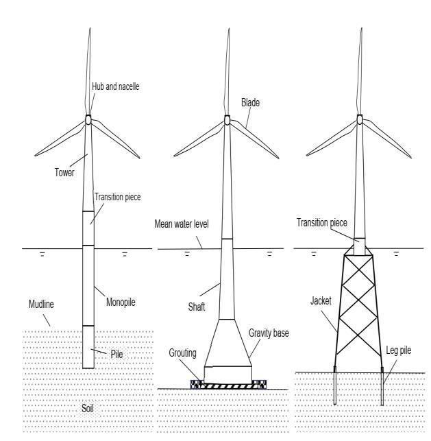
Coxet.al[13]studyInshorewindturbinesareextremely sensitivefordynamicloading,becauseofthecombinationof thethinstructuralnatureoftheturbineandthelargerange of cyclic loads to which the turbine is subjected. The unplanned resonance effects of the wind turbine can be minimizedbyproperdesigningof magnitudeofthedynamic load.Inseismicareastiltingwillbeconsiderasanimportant design parameter with liquefaction susceptibility. . Bhattacharyaet.al[6]studied thattypically,8 16msoilmay liquefyinloosetomediumdensedepositundermoderateto strongearthquakes.Thiswillreducetherotationalstiffness of the substructure, causing higher tilting along with settlement studied by Figure 4 shows schematic representationofmonopile,gravityandjacket foundations
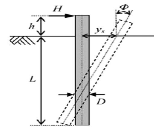
Typicalverticalloadona2 to5 MWOWTfoundationis2.4 10MNsettlement.TheinstallationofOWTisuniquedueto theirgeometry andthecyclic/dynamicloadsactingonit.in sea Figure6showstwistandlateraldeformationofmonopile under static loading. Where D is monopile diameter, L is embedmentdepth,histhe distancebetween pileheadand thesoilsurfaceandHisthelateralload
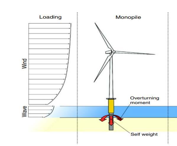
Fig -5:LoadsonMonopileFoundation[6]
Wuet.al[14]studiedthelateralstability,offshorewind turbine monopile foundations must be constructed with suitable embedment depth and diameter. In practice, monopile stability assessments are frequently done separatelyforaxial andlateralloadscenarios.Athorough, detailed investigation is necessary due to the relatively limited information available on the interaction effect of monopole behaviour under combined axial and lateral pressure Theultimateaxialload carryingcapacity(Qd)ofa monopileiscalculatedasfollows:
Qd =Qf +Qp =fAs+qAp
4. EFFECT OF LOADS
Bhattacharya et.al [6] studied loads applied on the foundation is depending on the foundation system. These loadscanbecategorizedintotwoie.staticloadsduetothe dead weight of the components and dynamic loads due to wave,1P,3Pandwindloads.Thedynamicloadduetowindis calculatedbyturbulenceintensityinthewindvelocityandit isactedatthehublevel.Thecyclicloadduetowaveisacting atthesubstructureleveloffoundationanditisdependingon waterdepth,waveheight,waveperiodetc.Therotorandhub massimbalanceandthebladeaerodynamicimbalancecause overturning moment and vibrations at the hub level settlement.Figure5showsloadsonamonopole.Malhotra et.al [16] found that monopile foundation of in sea wind turbines experience a vertical load by the weight of the superstructurecontainingtheturbineandtransitionpieces.
WhereQf isskinfrictionresistance(kN),Qp istotalend bearing(kN),fisunitskinfrictioncapacity,(kPa),As isside surfaceareaofpile(m2),qisunitendbearingcapacity(kPa), andApisgrossendareaofpile(m2)
Fig -6:LateralDeformationMonopile[8]
Fig 4:SchematicRepresentationofMonopile,Gravityand Jacket FoundationsWang et.al [3] investigates bucket foundation settles graduallyastheverticalaxisloadincreases,resultinginthe formationofalocalshearfailurezone.Astheexternalloading increases,a triangularwedge shapedzoneofsoil isforced down that will results the pushing of surrounding soil sidewaysandupwards.Attheultimateconditionthesoilwill reach a state of plastic equilibrium, then the foundation undergoes a large settlement without increase of vertical loadings. The bearing capacity of soil is increase with the skirtslength.Lianet.al[20]studythelargerdiggingdepth andcontactsurfaceareawillenhancefrictionresistanceof bucket foundation constraint effect on the inside soil enhance strength of bucket skirt at larger penetration depth,andhence resultinginhigherinternalsoilpressure. Bhattacharyaet.al[6]studiedthestresscausedbythethrust of the wind on the rotor blades and tower. The periodic componentoftheloaddependsontheturbulenceofthewind at that location (Changes in wind speed with time) and characteristicsofturbineoperations.Theequationforthrust force(Th)duetowindisgivenby
Th=0.5��aARCTU2
where��aisthedensityofair,ARistherotorsweptarea,CT isthethrustcoefficient,andUisthewindspeed
Usually Morison equation is adopted to calculate the wavesloadactingoncylindrical componentoffixedocean structures,whosediametershouldlessthanonebyfifthof the wave length [19]. Chen et. al [1] examines Morison equationisgiven
dF=¼(πD2)CMρudz+ρ/2CDDuꞌ |uꞌꞌ|dz
where dF is the horizontal wave load acting on a strip lengthofdzinN,Disthediameterofthecylindricalmembers in m, uꞌ and uꞌꞌ are the wave induced velocity (v) and acceleration (a) of water particles respectively in the horizontal direction, CM and CD are the mass and drag coefficients,ρisthewaterdensity.
5. SOIL STRUCTURE INTERACTION
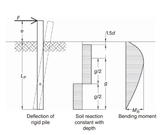
Soil structureinteraction(SSI) isaprocessitisdefined as the, response from the soil affects the motion of the structureandthevibrationofthegivenstructureinfluences the response from the soil. Bhattacharya et.al [6] studied that structuralshiftsandtheearthdisplacementsarefreeof each other. SSI forces can happens for any structure. But theseareimpossibletochangethesoildriftinallconditions. Soil structureinteraction(SSI)affectstheoverallbehavior of the wind turbine system in mainly three ways ie. load transfer mechanism ,modes of vibration and long term performance. When the subsoil resistance assumed with constantdepth,groundconditionsthen soils failsfirstand the pile failure is not through the plastic hinges shown in Figure7.Thentheultimatecapacitycanbecalculatedby
MR=FR(e +1.5DP +0.5 f )=2.25DPg2su
LP =1.5DP + f +g
f =FR/9suDP
Fig -7:LateralPileCapacity GroundStiffnessconstant withdepth[6]
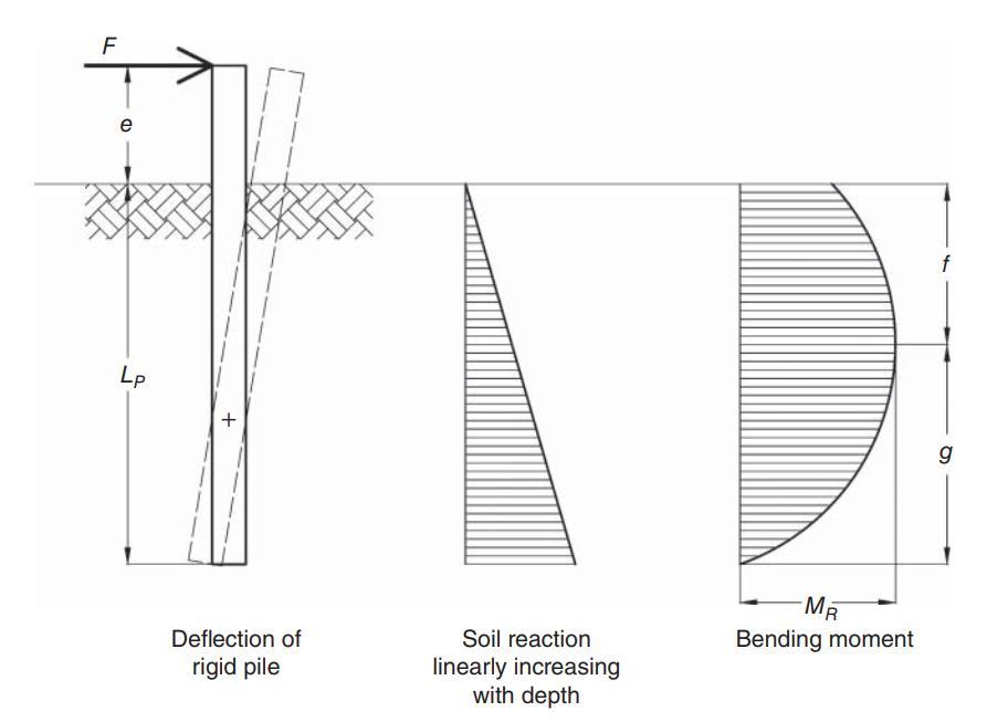
where e istheloadingeccentricity,su istheundrained shearstrengthofsoil,MR isthemomentcapacity,FR isthe pile horizontal load carrying capacity , DP is the diameter andLPistheembeddedlengthofthepile.Similarly whenthe subsoil resistance assumed that increasing linearly with depth,inthiscase soilisfailsfirstandno plastichinges is formedinthepilethatisshowninFigure8.
Fig 8:LateralPileCapacity GroundStiffnessLinearly withdepth[6]
Thentheultimatecapacitycanbecalculatedby
FR= ��′DPKP f 2
KP=(1+sin��′)/(1 sin��′)
MR=FR(e +0.667f)
Where e istheloadingeccentricity,su istheundrained shearstrengthofsoil,MR isthemomentcapacity,FR isthe pilehorizontalloadcarryingcapacity,��′and��′ arethe submergedunitweightandangleofinternalfriction respectively
Bhattacharya et.al [6] studied monopiles and jackets have very different load transfer mechanism in soil For a monopile,theinteractionis trasverse pile soilinteraction (LPSI)duetothelateralloadandtheoverturningmoment Inthecaseofjaacketthedominentinteractionisduetothe axialloadtransfer.HencetheSSIdependsonthetypeofsoil near the pile and the choice of foundation Types of foundation are the main factor that will affect modes of vibration
The shapes of shallow foundations are often square, circular, or rectangular, in plan. They will be even multi cellularandformudmatstheformareoftenirregular.The addition of skirts will help to improve the load bearing capacity of foundations. The main loads acting on the foundation are horizontal load (H), vertical load (V) and moment(M).Themomentcapacityisdefinedastheproduct of eccentric loading point and vertical load. Terzaghi’s bearingcapacityequationsareusedtofindbearingcapacity ofstipfootinganditisgivenasfollows
qult =c′Nc +��zNq +12��BN��
where qult is the ultimate bearing capacity which is expressedinN/m2 ,c′isthe apparentsoilcohesion,zisthe depthoffoundation,Bisthebreathoffoundation,��isthe unit weight of soiland Nc,Nq,N�� are the bearingcapacity factors.
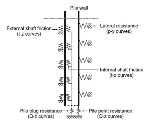
Bhattacharya et.al[6]studied thatmonopoleisalong pipehavinglargediameterfromageotechnicalpointofview, so proper substructure modeling is very crucial for the designofOWTmonopolefoundation.Thispilefoundations experience heavy bending moments due to horizontal(H) loadsexertedbywavesandwindontheslenderWTtowers. In traditional monopile response examinations, the sand resistance is typically modeled by discrete uncoupled springsthatisattachedtothetypical nodes.
Themonopileisdesignedtowithstandaxialandlateral static or dynamic loadings, and its corresponding deformationshouldsatisfystructuralandserviceability .For pile axial load settlement test the soil spring response is expressedbynonlineart zcurves,where tandzindicates mobilizedshaftfrictionandlocalpiledeflection.Forlateral load deflection test the soil spring response is indicate by nonlinearp ycurvesthatisasshowninFigure9 API[11] will provide the procedure for construction of t z and p y curves.
6. GEOTECHNICAL CONSIDERATIONS
Bhattacharya et.al[6]studiedthegeotechnical studies will help to determine the foundation capacity, the installation cost and procedure, foundation modeling and fatigue analysis etc. Based on study, the engineering behaviorofstandardoceansoilslikepuresandorpureclay canbeanticipatedwithsomelevelofconfidence.Sometimes itisdifficulttoforecasttheconductofintermediatesoili.e. clayey siltorsandy silt,asthemainquestions arewhether the samples will conduct like clay or sand material. Particularlythebehaviorofsoilwithvaryingfinescontentis difficulttoforecastandcyclictriaxialtestsareveryuseful. Thatwillhaveagreatimpactonthelong termbehaviorsoil.
Harriset.al[22]studiedScouringisonetheimportant challenge in foundation design and it is a combination of geotechnical and hydrodynamic process that affects soil structure fluidinteractions.Scouringwillbadlyaffectsthe bearing capacity of monopile, the dynamic characters of OWT systems and it will lead to structural instability. De et.al[23]studiedThestudiesaremainlyfocusonforecasting of scour depth, scour protection design and structural responseassessmentetc.
Fig -9:Soil PileInteractionSpringModel[9] Fig SuctionBucketBucketfoundationsarecommonlyusedforoffshoregas andoilproductionsshowninFigure10.Achmuset.al[24] andWanget.al[25] studiedthemainloadsonthesuction bucket OWT foundations are vertical load from the self weight,lateralloadsfromthewind,waterandoverturning momentsetc.StudiesofOWTbucketfoundationsaremainly concentratedonthebearingcapacitiesundervariouscyclic loading and monotonic loading and the primary aim is to provideasuitableandeconomicaldesignmethodologyfor bucketfoundation.
7. CONCLUSION
This paper provides the overview of types of offshore wind turbine foundations. The first part of the paper representsthehistoryandbackgroundofOWTfoundations, theimportanceofrenewableenergyresources,advantages of offshore wind turbine than onshore wind turbine etc. Then review follows the order of types of foundations ie, grounded system foundations and floating system foundations, OWT design considerations and effects of various loads etc. Various existing geotechnical issues are critically reviewed, and challenges along with scouring of foundationsarediscussed.Finallythedetailedfixingprocess ofmonopileandcaissonbucketarediscussed.
REFERENCES
[1] Chen,D.,Gao,P.,Huang,S.,Li,C.andYu,X.,(2020).“Static anddynamicloadingbehaviorofahybridfoundationfor offshore wind turbines”. Marine Structures, Vol.71, pp.102727
[2] Ma,H., and Yang,J.,(2020). “ A novel hybrid monopile foundation for offshore wind turbines. Ocean Engineering,Vol.198,pp.106963
[3] Wang, X., Zeng, X., andLi, J., (2019). “Vertical performanceofsuctionbucketfoundationforoffshore windturbinesinsand”.OceanEngineering,Vol.180,pp. 40 48.
[4] Velarde, J., Kramhøft, C., and Sørensen, J.D., (2019). “Global sensitivity analysis of offshore wind turbine foundationfatigueloads”.RenewableEnergy,Vol.140, pp.177 189.
[5] Ahmed, S.S, and Hawlader, B.,(2016). “Numerical Analysis of Large Diameter Monopiles in Dense Sand Supporting Offshore Wind Turbines”. International Journal of Geomechanics,,pp.04016018 doi:10.1061/(ASCE)GM.1943 5622.0000633
[6] Bhattacharya,S. (2019), “ Design of Foundations for OffshoreWindTurbines”,Wiley,USA.
[7] Perveen,R.,Kishor,N,.andMohanty,S.R.,(2004)“Off shore wind farm development: present status and challenges”.RenewSustainEnergyRev,Vol.29,pp.780 792.
[8] Achmus,M, Kuo,YS, and Abdel Rahman,K. ,(2009). “Behaviorofmonopilefoundationsundercycliclateral load”.ComputGeotech,Vol.36(5),pp.725 35.
[9] Zaaijer,M.,(2002)“Sensitivityanalysisforfoundations ofoffshorewindturbines”.SectWindEnergy,TUDelft
[10] Nikitas,G.,Vimalan,N.J.,and Bhattacharya,S.(2016). “Aninnovativecyclicloadingdevicetostudylongterm performanceofoffshorewindturbines”.SoilDynamics and Earthquake Engineering,Vol.82, pp. 154 160. doi:10.1016/j.soildyn.2015.12.008
[11] RP2A WSD A Recommended practice for planning, designing and constructing fixed offshore platforms working stress design . Paper presented at: Twenty 2000.
[12] Negro,V.,López Gutiérrez,J.S.,Esteban,M.D.,Matutano, C., (2014). “Uncertainties in the design of support structuresandfoundationsforoffshorewindturbines”. RenewableEnergy,Vol.63,pp.125 132. doi:10.1016/j.renene.2013.08.041
[13] Cox,J.A.,Bhattacharya,S.,andLombardi,D.,WoodMuir Wood,D.M.,(2013).“Dynamicsofoffshorewindturbines supportedontwofoundations”.ProceedingsoftheICE Geotechnical Engineering,Vol.166(2),pp.159 169. doi:10.1680/geng.11.00015
[14] Wu,X.,Hu,Y.,Li,Y.,Yang,J.,Duan,L.,Wang,T.,Adcock,T., Jiang,Z.,Gao,Z.,Lin,Z.,Borthwick,A.,andLiao,S.,(2019). “Foundations of offshore wind turbines: A review” . Renewable and Sustainable Energy Reviews,Vol. 104, pp.379 393.doi:10.1016/j.rser.2019.01.012
[15] Hermans, K, and Peeringa ,J. “Future XL monopile foundation design for a 10 MW wind turbine in deep water”,(2016) Technical Report, ECN E 16 069. The Netherlands:ECN;
[16] Malhotra,S.(2011).“Selection,designandconstruction ofoffshorewindturbinefoundations.”WindTurbines,I. Al Bahadly,ed.,InTech,Rijeka,Croatia
[17] Thomsen,K.,(2014).“Offshorewind:acomprehensive guide to successful offshore wind farm installation”. AcademicPress;
[18] Castro Santos ,L,and Diaz Casas, V.,(2006). “ Floating offshorewindfarms”.SpringerInternationalPublishing
[19] DNV. “Design of offshore wind turbine structure”.(2010)DetNorskeVeritasAS.
International ISSN: 2395 0056
Volume: 09 Issue: 04 | April 2022 www.irjet.net ISSN: 2395 0072
[20] Lian,J.,Chen,F.,andWang,H.,(2014).“Laboratorytests onsoil skirtinteractionandpenetrationresistanceof suction caissons during installation in sand”. Ocean Eng.Vol.84,pp.1 13
[21] Dong ,W, Moan, T, and Gao,Z.,(2011). “ Long term fatigueanalysisofmulti planartubularjointsforjacket type offshore wind turbine in time domain”. Eng Struct,Vol.33,pp.2002 14
[22] Harris,J.M.,WhitehouseRJS.(2017)“Scourdevelopment around large diameter monopoles in cohesive soils: evidence from the field”. J Waterw Port Coast Ocean Eng,Vol.143(5)
[23] De,V.L., De,R. J, Troch ,P,and Frigaard,P.,(2011) “Empiricaldesignofscourprotectionsaroundmonopile foundations: part 1: static approach”. Coast Eng,Vol.58(6),pp.540 53
[24] Achmus,M.,Akdag,CT.,andThieken,K.(2013).“Load bearingbehaviorofsuctionbucketfoundationsinsand”. ApplOceanRes,Vol.43(5),pp.157 65.
[25] Wang, X., Yang ,X., and Zeng,X., (2017). “Seismic centrifuge modelling of suction bucket foundation for offshorewindturbine”.RenewEnergy,Vol.114.