International 2395-0056 09 2395-0072
Smart Walking Blind Stick For Visually impaired Using Iot
1Dept. of Information Technology, Atharva College of Engineering, Maharashtra,

2Assistant Professor, Dept. of Information Technology, Atharva College of Engineering ,Maharashtra
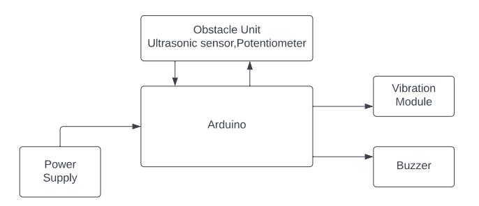
Abstract It is very challenging for visually impaired people to detect the object coming from thefront, left, and right sides while walking on the street or crossing the traffic signal. If the individual has a hearing disability along with blindness, it becomes very difficult to travel out of the home. Being blind in this modernized generation is very difficult to survive because they face lots of problems in their day to day life. There is always fear in their family that while crossing theroad, traveling by train, he might not get injured. To make it a little bit more simple and easy, we came to a solution in the form of a blind stick. This stick consists of three ultrasonic sensors, a buzzer, a potentiometer, threevibrating motor, an Arduino Uno, and a transmitter.
Key Words: blind, buzzer, Arduino Uno, transmitter, ultrasonic, potentiometer, visually impaired .
1. INTRODUCTION
In accordance with recent figures, there are about 285 millionvisuallyimpairedpeopleworldwide.Outofwhich,39 millionarecompletelyblind.Thesemanypeoplecannotsee thisbeautifulplanet.Oftentheyfacelotsofproblemsintheir dailylife.Manyofthemdohavearesponsibilitytolookafter theirfamilyanddotheirjob.Whilegoingforthejob,which isverydifficultforthemtofind,theydofaceobstacles.The blindstick isa giftforthem. Thenew blindstick will help them to navigate using advanced technology. As this stick alsoconsistsofavibrationmodulewhichwillbehelpfulfor peoplewhocan’thear,astheycanfeelthevibrationinthe stickinthreedifferentdirections,whichwouldhelpthemto detect an object. They can also adjust the distance of the obstacleusingapotentiometerwhichwillbeinstalledonthe stick.
2. LITERATURE REVIEW
[A] HarpreetSingh,V.B.KirubanandproposedSmartStick forBlindPeopleUsingIoT.InwhichtheydiscussedtheYolo algorithm and compared it with the existing method. Keeping the cost of the stick minimal, they used the GPS trackingfortheblindstick.Their futurescopealsowasto make the entire process fast and more efficient for the detectionofobjects.
[B] Niveditha K, Kavya P D, Nivedha P , Pooja B, LakshmikanthaGCsuggestedvirtualEyeforBlindusingIoT. TheyusedGPStechnologywhichwasintegratedwithpre
programmed locations which helped to determine the optimal route to be taken. They used raspberry pi as the main device because of its compatibility with the ARM [C]processor.Antara
Ghosal,AnurimaMajumdar,PalasriDhar,Adrija Kundu,AvirupMondal,AnanyaBiswas,BikramSaha,Palabi GhoshproposedSmartstickforblindusingiot.Theyusedan ultrasonicsensor,Flamesensor,andwaterlevel detecting sensorwhichshowedagoodresultfordetectingobstacles for a range of 4 meters. The system was low cost and effective
3. SYSTEM CONFIGURATION
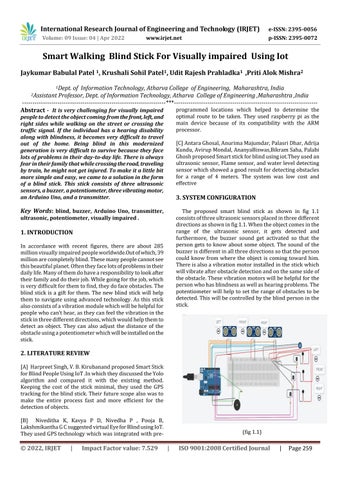
The proposed smart blind stick as shown in fig 1.1 consistsofthreeultrasonicsensorsplacedinthreedifferent directionsasshowninfig1.1.Whentheobjectcomesinthe range of the ultrasonic sensor, it gets detected and furthermore, the buzzer sound get activated so that the person gets to know about some object. The sound of the buzzerisdifferentinallthreedirectionssothattheperson could know from where the object is coming toward him. Thereisalsoavibrationmotorinstalledinthestickwhich willvibrateafterobstacledetectionandonthesamesideof theobstacle.Thesevibrationmotorswillbehelpfulforthe personwhohasblindnessaswellashearingproblems.The potentiometerwill helptosettherangeofobstaclestobe detected.Thiswillbecontrolledbytheblindpersoninthe stick. 1.1)
JaykumarResearch Journal of Engineering and Technology (IRJET) e-ISSN:
Volume:
Issue: 04 | Apr 2022 www.irjet.net p-ISSN:
© 2022, IRJET | Impact Factor value: 7.529 | ISO 9001:2008 Certified Journal | Page 259
Babulal Patel 1, Krushali Sohil Patel1, Udit Rajesh Prahladka1 ,Priti Alok Mishra2
India
,India ***
(fig
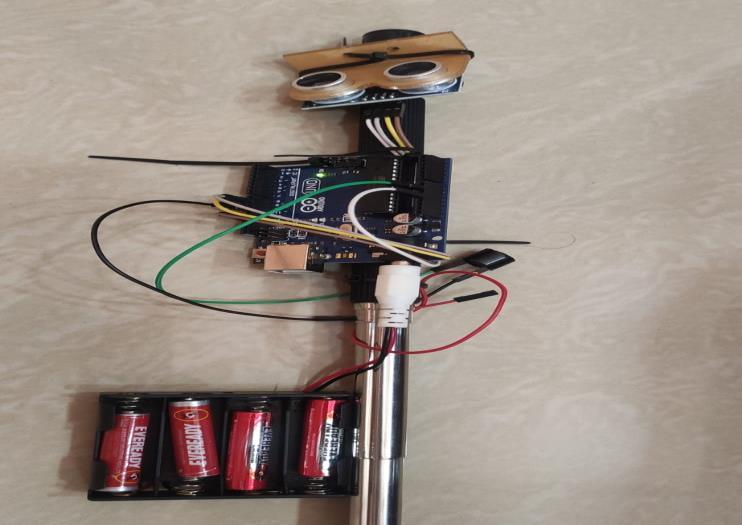
Infigure1.2,hardwareimplementationcanbeseenonone side.Whereanexternalpowersupplyisused.Thesimilarly ultrasonicsensorwillbefittedontheresttwosidestodetect objectsfromtheleftandrightside.
(fig1.2)
4. METHODOLOGY
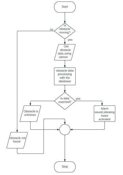
We have introduced a blind stick that not only helps visually challenged people but also people with hearing disabilitiesalongwithblindnesstonavigatesafely.Theblind stick is combined with an ultrasonic sensor and a potentiometer.Thisprojectwilluseultrasonicsensorstofind the obstacles using ultrasonic waves. After detection, the sensor will then transfer the information to Arduino Uno. Then the Arduino UNO processes the info and determines whetherornottheobstacleisclosetoenough.Ifthebarrier isn'tclosingthecircuit,nothingcanhappen..Ifobject isnear thesensorthenthealarmwillgetactivated.TheSmartStick blockdiagramisshownin
[A]. CONNECTION DIAGRAM
(Fig1.4)
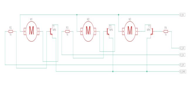
• TheVccattachtothe5VArduino.
• The trigger and echo pin of the Left side ultrasonic sensorattachtoArduinodigitalpin13andpin10.
• The trigger and echo pin of the Front side ultrasonic sensorattachtoArduinodigitalpin12andpin9.
• The trigger and echo pin of the right side ultrasonic sensorattachtoArduinodigitalpin13andpin10.
•ThepotentiometerisconnectedtotheArduinoanalog pinA0.
• ThebuzzerisattachedtoArduinodigitalpin7.
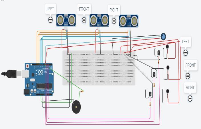
• The negative end of all three vibration modules is attachedtothetransistorcollectorend.Theemitterendof allthreetransistorsisattachedtotheground.
• Thetransistorbasefortheleft,front,andrightvibration motor attach to Arduino digital pin 5, pin 4, and pin3 respectively.
International Research Journal of Engineering and Technology (IRJET) e ISSN: 2395 0056 Volume: 09 Issue: 04 | Apr 2022 www.irjet.net p ISSN: 2395 0072 © 2022, IRJET | Impact Factor value: 7.529 | ISO 9001:2008 Certified Journal | Page 260
(FigFig.2.2)
[B] ARDUINO UNO
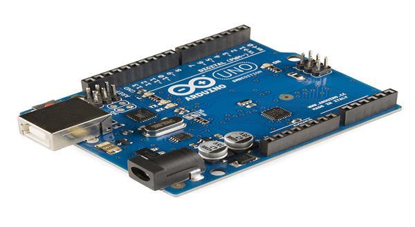
ArduinoUnoisthemicrocontrollerboardthatisbasedon the ATmega328P. The board consists of 14 digital pins. There consists of 6 analog inputs as well as 16Mz quartz crystal.Alongwiththese,apowerjack,resetbutton,aUSB connection,andanICSP
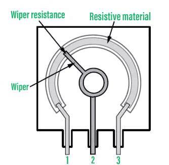
[E] POTENTIOMETER
It is a three terminal variable resistor. Over here the resistance is varied manually to control the flow of the electriccurrent.
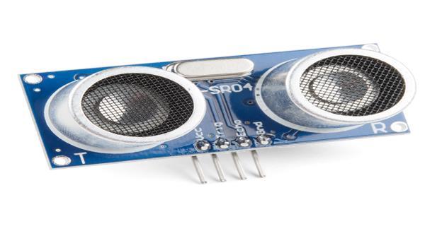
[C] ULTRASONIC SENSOR
TheUltrasonicsensoratthecoreconsistsof2transducers fromwhichonewillactasthetransmitterwhichworkisto convert an electrical signal into 40 kHz of the ultrasonic sound pulse. The other one acts as the receiverlistenstothetransmittedpulse.Afterreceivingthe pulseitwillproduceanoutputpulse.
It'sjustlikeavoltagedivider.(Fig
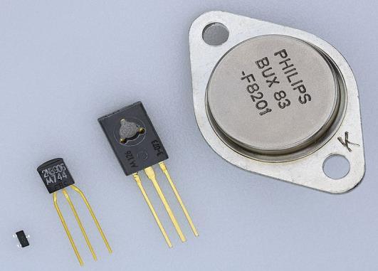
[F] TRANSISTOR
Atransistorisa semiconductordevicethatisusedforthe amplification of electrical signals. It consists of three terminalsforconnection.
It consists of three pins including an emitter, base, and collector.
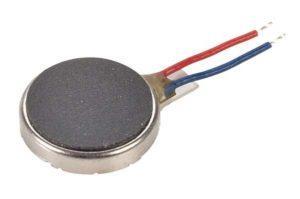
[D] VIBRATION MOTOR
A vibration motor is a DCmotor in a compact size that is usedtoinformtheusersbyvibratingonreceivingsignals.It hasnosound.
(Fig6)
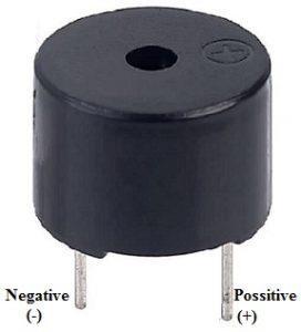
[G] BUZZER
It is an audio signaling device just like the buzzer which mightbeapiezoelectrictype.
Itsmainworkistoconvertthesignalfromaudiotosound.It has2pinsincludingpositiveandGND.
International Research Journal of Engineering and Technology (IRJET) e ISSN: 2395 0056 Volume: 09 Issue: 04 | Apr 2022 www.irjet.net p ISSN: 2395 0072 © 2022, IRJET | Impact Factor value: 7.529 | ISO 9001:2008 Certified Journal | Page 261
(Figheader.2)
Echo,accuracyThesensordetectionrangeisbetween2cmto400cmwithanof3mm.Thereconsistsof4pinsincludingVcc,Trigger,andGNDinthesensor.(Fig3)
(Fig4)
5)
International Engineering Technology (IRJET) ISSN: 2395 0056 09 Issue: 04 | www.irjet.net ISSN: 2395 0072
7. RESULTS
Thispaperwassuccessfullytestedandimplementedin tindercadandpartiallyimplementedinthehardwaremodel. Inthesoftwaremodel,whenevertheobjectcamenearbyto the sensor it got detected by the distance (dist1 = dur1 * 0.034 / 2) which was the default . The potentiometer was provided to change the distance accordingly and it give successfulresultsfordetectingobjects.Thetoneofthebuzzer was different for three sides which also sounded perfectly accordingtotheinputprovidedforadifferentfrequencies. The vibration motor was also implemented successfully according to their object's direction it vibrated . In the hardware model prototype of the stick was made and one sidedetectionwassuccessfullytested.
8. CONCLUSION
This paper presents the detection of object using the ultrasonic sensor on a blind stick and to make alert them using a buzzer of a different tone with respect to their direction.Thevibrationmotorwasalsoalertedalongwith thealarm.Additionalaspectsofthisdevicecanbeenhanced by wireless connectivity between system components, thereby increasing the range of the ultrasonic sensor and introducing technology to evaluate the speed of obstacles approaching.
REFERENCES
[1] Raghav Mohindru, Priyanka Jain, Nikhil Khosla , Smart Walking Stick for the Visually Impaired , International Research Journal of Engineering and Technology (IRJET) e ISSN: 2395 0056 Volume: 07 Issue:01Jan202p ISSN:2395 0072.
[2]HarpreetSingh,V.B.Kirubanand,SmartStickfor Blind People Using IoT, International Journal of Emerging Science and Engineering (IJESE) ISSN: 2319 6378,Volume 6Issue 2,March2019.
[3] Niveditha K, Kavya P D, Nivedha P, Pooja B, LakshmikanthaGC,VirtualEyeforBlindusingIoT, International Journal of Engineering Research & Technology (IJERT) ISSN: 2278 0181 Published by, www.ijert.orgIETE 2020.
6. FUTURE SCOPE
Ourbasicgoalistomakethisblindstickataveryminimal costsothatitcanbeeasilyaffordabletoallvisuallyimpaired aswellaspeoplewithblindnessandhearingproblems.To addGPStothestick,sothattheirfamilymemberscantrack themanytime,anywheretheyarelocated.AlsoaddanSOS button on the stick, so that in dangerous situation their family members can get alerted as well as know their locationtohelpthem
[4]AntaraGhosal,AnurimaMajumdar,PalasriDhar, AdrijaKundu,AvirupMondal,AnanyaBiswas,Bikram Saha, Palabi Ghosh ,Smart Stick for Blind using IoT ,October2020|IJIRT|Volume7Issue5|ISSN:2349
https://www.arduino.cc/en/main/arduinoBoardUno[5]6002.
Research Journal of
and
e
Volume:
Apr 2022
p
© 2022, IRJET | Impact Factor value: 7.529 | ISO 9001:2008 Certified Journal | Page 262 (Fig7) 5. FLOW CHART
International Research Journal of Engineering and Technology (IRJET)
e ISSN: 2395 0056
[6] https://www.sparkfun.com/products/15569 , UltrasonicDistanceSensor HC SR04.
[7] https://techzeero.com/arduino tutorials/vibration motor with arduino/, Vibration MotorwithArduino.
[8] applications/,[10]Transistor[9]Definition,definitionhttps://www.geeksforgeeks.org/potentiometerworkingprincipletypes/,PotentiometerWorkingPrinciple,Types.https://en.wikipedia.org/wiki/Transistor,https://www.elprocus.com/buzzerworkingBuzzer
Volume: 09 Issue: 04 | Apr 2022 www.irjet.net p ISSN: 2395 0072 2022, IRJET | Impact Factor value: 7.529 | ISO 9001:2008 263
©
Certified Journal | Page