
Design and Thermal Analysis of an Automotive Radiator for enhancing Flow Uniformity using CFD
Rama , M. Anil kumar , Arun Teja Vemunuri , Naga Teja Valusa , MD. YasinAssistant professor, Department of Mechanical Engineering, Kakatiya Institute of Technology and science Warangal, Telangana, India

UG students, Department of Mechanical Engineering, Kakatiya Institute of Technology and science Warangal, Telangana, India
Abstract - Aradiatorisadevicethatreducestheamount of heat generated by internal combustion engines. These heat exchangers are widely used to cool the engine block while maintaining the optimal temperature. Coolant is permitted to flow through channels in the engine block. Recent innovations have revolutionized the way manufacturerschoosematerialsforvehicleradiators,such as aluminium. Many of the large power supply engines seeninsupercars,locomotives,andairplanesnecessitatea long lasting radiator. To increase the radiator's life, the flow homogeneity in the radiator tank must be improved. To achieve improved flow homogeneity, a three pass radiator is used, which has better impact on radiator performance. The design parameters of an automotive radiatorhavebeenoptimisedbyloweringthetubesize of single pass radiator and transforming it to a three pass radiator.TheANSYSFLUENTsoftwareisusedtocarryout theCFDanalysisandThermalanalysis.Thedesignwillbe dependable,lighter,andmoreefficient.
Keywords: automotive radiator, heat exchangers, CFD analysis,thermalanalysis,ANSYSFLUENT
1. Introduction
In terms of performance, fuel economy, aesthetics, and safety, the automobile industry is constantly in a competitive position to deliver the greatest vehicle designs. Radiators, air conditioner condensers, and so forth are air cooled heat exchangers that have a considerable influence not only on product weight, but also on the development of front end modules, which has a profound effect on the aerodynamic performance of a car. In order to achieve the greatest possible design balance in terms of performance, size or shape, and weight, improved procedures are required for given challenges.
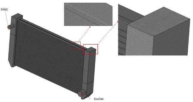
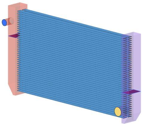
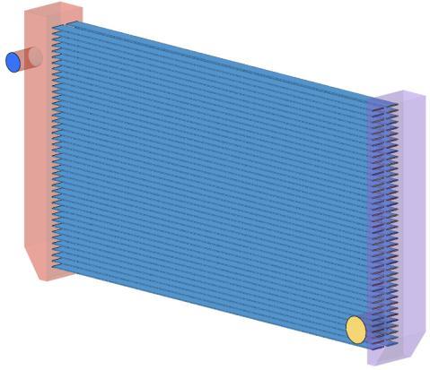
Anintaketank,anexittank,andacorearethethreesectionsof an automotive radiator. Two sets of passageways, tubes, and finsmakeupthecore.Theradiatorcoreiscommonlymadeout ofaflatmetaltubewithzigzagaluminiumfinsconnectingit.In engine cooling systems, two types of operating fluid are used: air and coolant. The coolant's purpose is to circulate and absorb heat throughout the engine block. Then, into the radiatortank,hotcoolantis been injected.Coolant fluid enters the radiator core through the tubes. When the fluid returns to thecounter tank,the majorityof the heat istransmitted tothe radiatortube,whichthendistributestheheattothefinsacross eachrowoftubes.Heatistransmittedfromthecoolantfluidto the air as it passes through the radiator. The role of air is to collect heat from the fluid and returns to the radiator at lower temperaturethanitwaswhenitfirstarrived.
CFD analysis has been utilised to solve a range of thermodynamic and heat transfer problems, including evaluating heat exchanger performance. Computational Fluid Dynamics (CFD), in addition to analytical and experimental methods, has become an important tool for solving and analysing fluid dynamics and heat transfer as a result of breakthroughs in engineering capabilities and computational information technology over the last two decades. Because of its use in the design process, CFD applications in industries including automotive and aerospace have increased in recent years. Commercial CFD software packages like as Autodesk CFD, Simscale, and Ansys Fluent have arisen as the industry's usageofCFDhasgrown.
Theeffectofvaryingthelengthoftheinletandoutflowsonthe pressure drop and the distribution of the maximum flow velocity were combined using a two dimensional model of the watertankandradiatorpipes,withtheGoldenSectionusedto findtheoptimal exitlocationfora givenone,thatis the height of the entryway, according to Laila Guessous and Sridhar Maddipatla [1].According toR.Paul Linga Prakash,M. Selvam, A.AlaguSundaraPandian,S.Palani,K.A.Harish[2],TheNozzle effect provides additional cooling to the engine by reducing
pressure, increasing speed, and lowering the temperature, which is directly proportional to the pressure, depending on the combined gas law. As a consequence,theradiatorandengine'scoolingefficiency is enhanced, and the engine's life is extended. The suggested radiator's efficiency increased by 5.37 percent.
Automotive radiators are constructed with automotive enginesinmind,andmassflowratesalongthetubesare calculated using CFD analysis. To obtain greater uniformityinflowratesacrossthetubes,thesinglepass radiator design is revised by lowering the tube size and reconstructedtoathree passradiator.Thermalanalysis is carried out to validate that the three pass radiator improvesflowratesoverthebasicradiator.Theanalysis is done in ANSYS FLUENT software. The objectives of thisresearchwere:
1.Changingtubesizetomaintainflowuniformity
2.ToFindMassflowratethrougheachtube.
3.ToFindTotalheattransfer.
4.ToReportcoolanttemperatureatoutlet.
5.Toanalyzemassflowdistributionintube.
6.Toreducetubecorrosionandcontamination.
7.ToExtendtheLifeoftheRadiator.
2. Methodology
2.1. Procedure
1. Problem Definition: To improve flow uniformity inradiatorbyconvertingsinglepasstyperadiator intothree passtypebyreducingtubesize.
2. Geometry Preparation: Prepared geometry of a RadiatorinCatiaV5software.
3. GeometryCleanup:Geometrycleanup,watertight geometryispreparedformeshing.
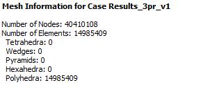
4. Meshing: Meshing with proper naming for inlet, outlet and wall is carried out with polyhedral elements, quality is less than 0.85 volumetric skewness.
5. ModelsetupandAnalysisisdoneinfluentsolver.
6. CFDPostisusedforResultsandpostprocessing.
7. Initiallyresultsarecalculatedforsinglepass,latersame methodisappliedforthree pass.
8. Resultsforboththeradiatormodelsarecompared.
2.2. Flow Uniformity
A radiator's performance and service life may be assessed using a variety of approaches. Initially, CATIA software was utilised to create a base radiator. Performance is measured using the flow non uniformity coefficient, which is calculated withthepurposeofenhancingpipeflowuniformity.
Flow non-uniformity coefficient:Toavoidcontaminationand pipecorrosioncaused byunderflow,eachradiatorpipeshould havethesamemassflowrateastherestoftheradiatorpipes.
= whereKisthetotalnumberofpipesortubesand isthetotal mass flow through the radiator. The pipe mass flow rate fraction is used to calculate the departure of a single radiator pipefromthisidealbehavior.
k=1,...,K
The mass flow rate through the pipe with the number k is denotedby Theidealvaluefor is1/K.However,using a single objective function to determine how evenly the heat exchanger flow is shared over several pipes would be more convenient.Thiscoefficient isthemodulusofthedivergence of each tube's mass flow rate from its ideal mass flow rate, normalisedtothetube'sideal massflowrate,andrepresented asfollows:
√∑ ( )
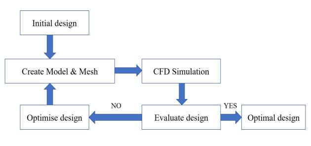
should be exactly equal to zero for an optimal flowrate distribution.Ifoneormoretubeshavezeroflowrate, should be more than one (>1). As a result, a value as near to zero as possible is preferred. The optimization strategy is depicted in figure1.
3. Design and Analysis of Radiator
3.1. Design Considerations
1. CATIA V5 R21 software was used to design the radiatormodels.
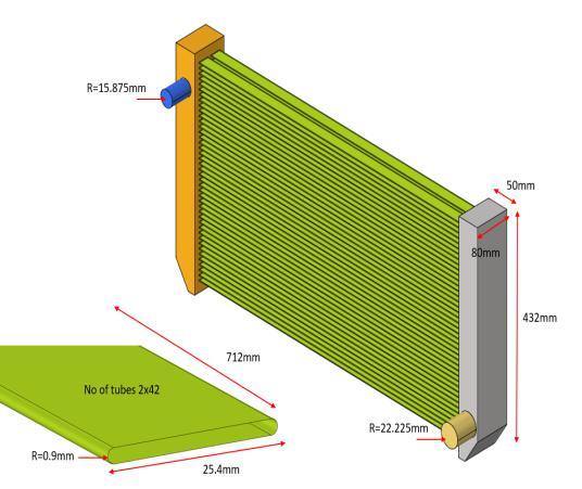
2.Radiatormodelsismadeupofaluminumconsistsof tworows,eachwith42tubes.
3. Radiator models are designed with a crossflow design.
4.AnsysFluentsoftwareisusedtodotheFlowrateand ThermalanalysisforCFDstudy.
Two types of radiators are designed as shown in TableI.
DimensionsofRadiatorareshowninTableII.
I.Radiatortypesunderconsideration
No Geometry
TableII.DimensionsofRadiator
Figure2.GeometryofSinglePassRadiator
3.2. Meshing
Meshes can also be categorized according to the size and type of elements they include. Meshing is classified based on connectivity and based on elements. Elements based classification consists of Mesh shapes that can be 2 dimensional(2D)or3 dimensional(3D)dependingonthetype ofanalysisandtherequirementsofthesolution.Trianglesand rectanglesaretypical featuresof2D.All themeshnodes inthe 2Dmeshlayinthesameplane.The2Dmeshnodeisusuallyon an XY plane, but may be on another Cartesian or user defined plane. Quadrilaterals and triangles are the most common 2D meshelements.
Nodes in a 3D mesh are not required to lie on a single plane. Hexahedra, tetrahedral, square pyramids and extruded triangles are the most common 3D mesh elements. Polyhedral elements,whichcanbeconstrainedbyanynumberandtypeof faces, are also supported by several modern solvers. Even thoughall3Delementsaredefinedby2Delements,3Dmeshes haveclearlyexposed2Delementsattheiredges.
of
Flow Rate
Boundary Conditions:
Velocityinlet:0.153741m/s

The rate is estimated using a 0.12 LPM volumeflowrateinsidetheradiator.

Pressureatoutlet=0pa

Walls:Thereisnoriskofslipping.
Everysurfaceisawallatthispoint.
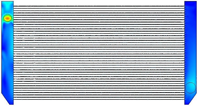
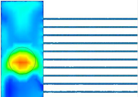
Figure9.VelocitycontourofathreepassRadiator
The velocity contour is performed to verify the change in velocity across the tubes and we can observe that there is an improvement in velocity of flow from the above contours (Figure 8 and Figure 9)
3.3.3. Pressure contours:

Figure10.PressurecontourofasinglepassRadiator
Figure11.PressurecontourofathreepassRadiator
Pressure contours are generated to verify the improvements in pressure drop and that can be observed from the above contoursgenerated(Figure10andFigure11).
3.3.4. Streamlines:

Figure12.TheStreamlinesofasinglepassRadiator


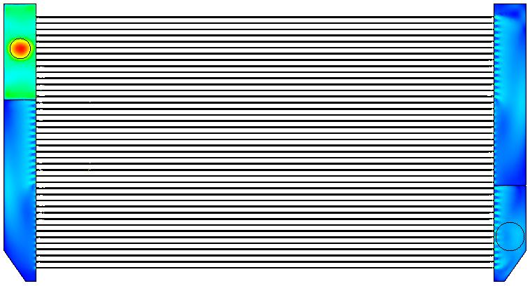
Figure13.TheStreamlinesofathreepassRadiator
Streamlinesaregeneratedtoverifyflowuniformityandfrom theabovecontours(Figure12andFigure13),wecanobserve theimprovementinuniformflowrate.
temperatureforthreepassmodel


pass
pass
observed from above
Three-pass
Single Pass Radiator
SpecificHeat,
Three Pass Radiator
isTotalHeatTransferRate
SpecificHeat,forwater
Changeintemperaturesofinletandoutlet
Observations from Thermal Analysis
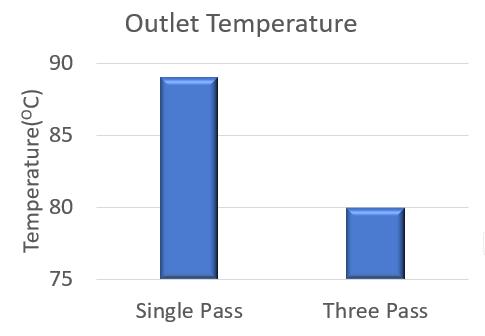
V. Outlet coolant temperatures and Heat Rejection
obtained from thermal analysis
Typeof Radiator
Single Pass Radiator
Pass
coolant temperature
Outletcoolant temperature
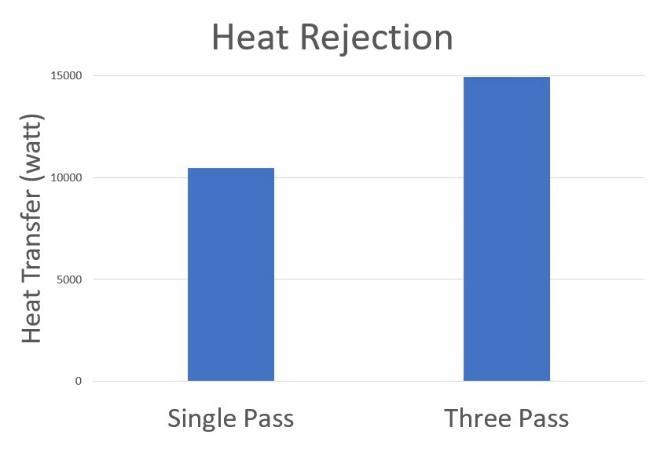
HeatRejection (watt)
10473.52
5. Results
FlowNon Uniformitycoefficienthasreducedby0.064.
In both Single pass and three pass models’ coolant inlet temperature
samei.e.,
Outlet temperature of coolant is 89 OC for single pass
80 OCforthreepassradiatormodel.
Theoretical calculation of Total Heat Transfer Rate in
pass radiator is 10532.24 watt and Total Heat TransferRateinthreepassradiatoris15046.06watt.
ThermalAnalysisobservationsofTotalHeatRejectedin single pass radiator is 10473.52 watt and Total Heat rejectedinthreepassradiatoris14929.63watt.
6. Conclusions
Accordingtothefindingsinflowrateanalysis,the value ofthreepassradiatoris reducedby 57% whencompared tothesinglepassradiator.Thedropin valueshowsthe increase in flow uniformity along the tubes in three pass radiator. As a result, the flow homogeneity of three pass radiator is improved which increases the life time of radiatorandpreventstubecorrosionandcontamination Thermal analysis results a temperature drop of 21OC for single pass Radiator and 30OC for three pass Radiator. A difference in temperature drop of 9 OC is observed for three pass radiator compared to single pass radiator. The total heat transfer rate is increased by 42% in three pass radiator compared to single pass radiator. As three pass model has more heat rejection rate and obtained less coolanttemperature atoutlet, wecanconcludethat three pass radiator is better and preferable than single pass radiator.
7. Future Scope
Thenextpartofthisresearchwilllikelyfocusonfinswith variousshapes. Finsplaysanimportantroleinimproving heat transfer rate. Using fins with different geometries in three passradiatorwouldimproveefficiencyofradiator.
8. References
[1] Improving Radiator Design with Shape Optimization, Proceedings of the IMECE2002 ASME International Mechanical Engineering Congress and Exhibition, New Orleans, Louisiana, 17 22 November 2002. IMECE2002 33888
[2] IC Engine Cooling System Radiator Design and Modification to Improve Efficiency and Lifespan, KA Harish,R.PaulLingaPrakash,M.Selvam,A.AlaguSundara
[3] Using nanofluids to improve the performance of car radiators, M. El Haj Assad, Ahmed Amine Hachicha, EvangelosBellos,et.al,RenewableandSustainableEnergy Reviews 112 (2019) 183 194, Elsevier Ltd. Zafar Said, M. El
[4] Using Multi Walled Carbon Nano Tubes to Improve Heat Transfer Coefficient in an Automobile Radiator (MWCNTS), Manikantan Kota, et. alASME 2014 InternationalMechanicalEngineeringCongress
[5] Parametric radiator research in automobiles, Applied Thermal Engineering 27 (2007) 2033 2043, Elsevier Ltd, C.Oliet,A.Oliva,J.Castro,C.D.Perez Segarra
[6] Raju Jadar, K.S. Shashishekar, S. R. Manohara, Nanotechnology Integrated Automobile Radiator, Proceedings 4 (2017) 12080 12084, 2214 7853, 2017 ElsevierLtd