and Technology (IRJET)

Volume: 09 Issue: 04 | Apr 2022 www.irjet.net
e ISSN: 2395 0056
p-ISSN: 2395-0072
PLANNING DESIGNING AND ANALYSIS OF FLYOVEER BY USING STAAD PRO
J HARSHAVARDHAN, C. RUKMUNNISA SULTHANA, C. NAGARJUNAABSTRACT
As the population is growing, urbanization is caused which results in increasing of traffic with usage in more number of vehicles for different means of transport. As stated above the growth of population and the usage of vehicles for their different means will automatically result in increase in flow of vehicles which is called as traffic. To overcome the issue of traffic getting jammed (which means having obstacles for free moment or flow at a particular place), there are many different ways implemented to overcome it. When coming to Highways one of the efficient ways of overcoming it is construction of a flyover.
Here in this project we are going to a design a flyover at Morampudi Junction located in Rajahmundry Andhra Pradesh along the National Highway 216A as a proposal in order to overcome the issue of traffic jam and also to reduce the rate of accidents occurring at the junction. By considering all the data collected conducting different examinations I am going to design and analyze the flyover using software STAAD Pro V8i to study Bending Moment, Shear Force, Nodal Displacement values by considering various types of loads considered are Dead Loads, Live Loads, Wind Loads, Vehicle Load which are taken from Indian Standard Codes IS 456, IS 800 & IRC: 6 2016.
1.1INTRODUCTION
Abridgeisaconstructionhavinganalloutlengthabove 6m for conveying moving burdens or passerby load and across the snag, a bridge is a design which is worked over an impediment and thus giving an entry without hinderingtheitem.Thesectionmightbeforarailroad,a street,apipeline,avalley,oratrench.Theimprovement of the nation in view of the framework accessible in the country. Parkway which permits the progression of people and vehicles is a significant piece of framework. thedevelopmentofbridgeisfundamentalwherethereis a weighty gridlock which brings about delay for the travelers.Developmentof bridgewilllessenthedeferral andpermitthevehiclestogowithoutinterference.
A bridge is a development worked to traverse actual obstructions like a waterway, valley, or street, to give section over the impediment. Plans of bridges fluctuate contingent upon the capacity of the bridge, the idea of theterritorywherethebridgeisdeveloped,thematerial utilized for development and the assets accessible to
fabricate it. A bridge has three primary components. In the first place, the base (establishment) moves the stackedloadofthebridgetotheground;itcomprisesof parts like sections (additionally called wharfs) and projections. A projection is the association between the finishofthebridgeandthestreetconveyedbytheearth; itoffershelpfortheendsegmentsofthebridge.Second, the superstructure of the bridge is the even stage that traverses the space between segments. At long last, the deckofthebridge.TherulesforNon directexamination for bridge structure presents an assortment of general proposals for the displaying and investigation of thruway bridges and bridges exposed to tremor ground movements, expected for the plan or assessment of the limitandpliabilityofbasicbridgepartsandframeworks.
In bridge thereare basicallytwo kindof stacking first is dead burden which is self weight of bridge going about as a UDL and second is live burden which is consider as vehicleloadwhichgoaboutasapointloadonthebridge and the other sort of stacking like breeze burden and effectloadandsoonwhicharetakenintotherecordas indicated by the circumstance. To shape a predictable premise plan, the IRC has fostered a bunch of standard stacking condition, which are considered and use while planningwhileatthesametimeplanningabridge.
The conceptional plan of flyover is finished by the assistance of STAAD professional programming. STAAD aceisanunderlyinginvestigationandplanprogramming application.Itisquitepossiblythemostbroadlyutilized primary investigation and the plan programming item around the world. It upholds north of 90 global steel, cement, wood and aluminum configuration codes. It can utilizedifferenttypesofexaminationfromthecustomary static investigation to later investigation strategies like p delta investigation, mathematical non direct examination, clasping examination and so forth.. STAAD professionalcanbeutilizedforexaminationandplanofa wide range of primary activities from building and bridges to towers, burrows, metro stations, water/squanderwatertreatmentplantsandthensome
2. COMPONENTS OF PROPOSED SYSYTEM
India is the country with the second biggest street network across the world with 5.4 million Km. This street network helps transportation over 60% of generallymerchandiseinthenationand85%oftraveler trafficinIndia.Streettransportationframeworkhasstep
Research Journal of Engineering and Technology (IRJET)
Volume: 09 Issue: 04 | Apr 2022 www.irjet.net
by step expanded over yearswith the improvement in availability between urban communities, towns and towns across thecountry. One of the significant parts of streetsifFlyover‟s.
Prologue to Flyover: Flyover might be alluded as a bridge,ahigh levelstreetbridgethatgoesacrossovera parkwaytradeorconvergence.Adevelopmentisworked overactualsnags,forexample,waterbodies,valleysand streets which are accommodated section over the impediment. Plans of flyover differ contingent upon the prerequisites and functionalities of the flyover, the idea ofthedirtwheretheflyoverisbuilt,thematerialthatare utilized for development and the assets accessible to constructit.
Flyover The primary flyover on the planet was developed and begun in the year 1843 by the London and Croydon Railway division at Norwood Junctionrailway station to convey its barometrical railroad vehicles over the Brighton Main Line. In India themainflyover wasbuiltandpermitted toaccessfrom 14April1965inKempsCornerinMumbai.Thelengthof the bridge was 48‟ (foot) which was built in around seven months by Shirish Patel with the consumption of 17.5needs.
A flyover comprises of, number of ranges with sections (docks),deck,andestablishmentandsoforth. Tobuilda flyover this multitude of components are to be planned appropriatelysubsequenttoinvestigating.Forenormous development the most common way of planning and dissecting for the design becomes confounded when done physically, it consumes part of time and may prompt initiation of blunders additionally, to meet the prerequisites of the proposed development and completetheundertakingwithnoissues,programming's are utilized for proficient work. The product's are utilized to perform examination and planning with less exertion and no blunders with in brief timeframe, by which the planning of mind boggling flyovers become more straightforward utilizing different programming's. Aportionoftheproduct'swhicharebyandlargeutilized for investigation and planning of constructions are ETABS,ROBOTSTRUCTURELANALYSIS,STAAD.ProV8i.
Aflyoverhasthreeprinciplecomponents.Firstthebase, whichisknownasestablishment,thatwhichassimilates and moves the heap and weight of the bridge to the ground. It comprises of parts like sections (additionally called docks) and projections. A projection is the association between end of the bridge and the street conveyedbytheearth;itoffershelpfortheendareasof the flyover. Besides, the superstructure of the flyover is theflatstagethattraversesthespacebetweensegments. Atlastitcomestothedeckofthebridge.
PRAPOSED SYSTEM
e ISSN: 2395 0056
p-ISSN: 2395-0072
Our country being fundamentally a horticultural country, 90% of populace is relying on it and 10% of populacerelyingonmodernexercises.Forconveyingthe item materials, for example, food grains, modern products the streets are fundamental. The streets and bridges was extremely fundamental for development of economyofthecountry.Theexpenseoftrustingthatthe sign will change, as well as the deficiency of fuel for ignition, are both not entirely settled to be significant. Whenever it downpours, not just the parkways become overwhelmed; any remaining roads become overflowed too,makingithelpfultogobyflyovertokeepawayfrom flooding.[1]. Numerous strategies was foundation for investigationofbridges,forexample,grillageandlimited component techniques and so forth. Grillage investigation is the greatest common and comprehensively involved strategy for examination and plan of bridge. For the development of bridges with medium and long ranges Concrete that has been pre pushed is the most ideal choice. Since Freyssinet's innovation of prestressed concrete, the material has observed boundless use in the development of long rangebridges,stepbystepsupplantingsteel,whichhasa high support cost because of its intrinsic hindrance of erosion in outrageous conditions. Precast braces with cast in situ chunks are quite possibly the most well knownkindsofsuperstructureinsubstantialbridge.For ranges of 20 to 40 meters, this type of superstructure is utilized. The most common kind of bridge in this classification is the T or I brace bridge, which are especially famous because of its straightforward math, simplicity of erection or projecting, diminished dead loads,andcheapmanufacturecosts.
PresentationABOUTGIRDER
Support:
A brace is a kind of development support bar. It is a design'sreallyevenhelpthat upholds more modest bars. Braces typically have an I pillarcrossareawithtwoburdenbearingspines isolated by a balancing out web, in any case they will in likemannerneedacrate,Z,orothershape.Bridges aregenerallybuiltwithbraces. Inthiscurrentreview
PresentationABOUTGIRDER
Brace:
A brace is a sort of development support pillar. It is a construction'sreallyevenhelpthat
upholdsmoremodestpillars.Supportsnormallyhavean I pillarcrosssegmentwithtwoburdenbearingribs
Research Journal of Engineering and Technology (IRJET)
Volume: 09 Issue: 04 | Apr 2022 www.irjet.net
isolatedbyasettlingweb,inanycasetheywillsimilarly requireacrate,Z,orothershape.Bridges areforthemostpartbuiltwithbraces.
Inthiscurrentreview
PresentationABOUTGIRDER
Brace:
A brace is a sort of development support pillar. A construction's really even help upholds more modest pillars. Braces ordinarily have an I shaft cross segment withtwo burden bearing ribsisolated by a settling web, regardlesstheywillmoreoverrequireacrate,Z,orother shape.Bridgesareforthemostpartbuiltwithsupports.
Sortsofbraces:
Thereare3kindsofbraces,thatis
1.Rolledsteelsupportbridge
2.Platesupportbridge
3.Boxsupportbridge
1.Rolled steel brace bridge:
A moved steel brace was one that have been made by turninganunfilledsteelchamberacrossaprogressionof kicksthebuckettoaccomplishtheidealstructure.These produce 100 foot long normalized I bar and wide rib pillarshapes
2. Plate brace bridge:
A plate brace was a sort of support that is made by welding plates together to deliver an ideal shape. Plate supportscanbetallerthanmovedsteelbracesanddon't need to adjust to uniform shapes. Plate braces can traverse distances going from 10 meter to in excess of 100m.
3. Box support bridge:
Box brace is a one sort of support it is looking like box. They are prepared up of two opposite networks, short top ribs from each, and an enormous base spine that interfacesthenetworks
InthisstudyAcommonplaceteepillarbridgeisthinking abouthavingthepartlongitudinalbrace,persistentdeck chunk and cross shaft, the cross supports are given a sidelong unbending nature to the bridge deck. The deck piece is plan by pigeaudsmethod and the longitudinal and cross support is configuration by courbon's technique the specific bridge model is taken then that model is examination and plan on the staad expert and furthermore investigation and plan with physically.
e ISSN: 2395 0056
p-ISSN: 2395-0072
Result are contrasting between staad expert and physically and considering the class An and class AA followedloadings.
3.1 Staad master method:
Staad master in space is Operated with unit meter and Kilo Newton. the properties of area are doled out to the bridge. Fixed Supports are taken. Quadrilateral cross section is finished by ¼ of the aspect taken followed by doling out of plate thickness.3D delivering can be seen. Loads are taken by the heaps and definitions. By Post Processing mode, Nodal dislodging, Max. Outright Stress an incentive for the bridge can be seen and Run investigation is worked. Then, at that point, go through the bridge model making a deck characterizing appropriate carriageway width in characterize street way after that IRC stacking are applied and afterward pursue as burden generator that for substantial plan code IS 456 is utilized that code is applied on all the component lastly run and investigation order is utilized tolookattheoutcome.
3. RESULTS AND ANALYSIS
Reaction on outer girder =w1= (350*2.53)/3=295.16kn, w2=(350*0.48)/3=56kn,totalonoutergirder=349.99kn
Reactiononinnergirder=w1=(350*0.475)/3=55.416kn, w2= (350*2.525)/3=294.58kn, total on inner girder=351.16kn
MaxS.Fonoutergirder(349.96*16.2)/18=314.996,max S.F on inner girder = (351.2*16.2)/18=316.04, total S.F(dl+ll)=702.11kn
Ast = 13921.38, 11 number diameter 40mm, stirrups=10mm @250 c/c spacing provided at support, andatcenter10mm@300mmc/cspacing.
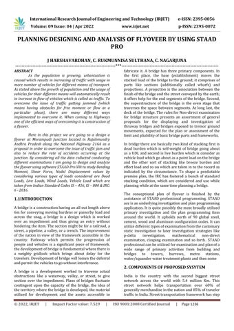
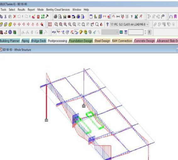
Fig1ClassAAtrackedloadinginstaadpro
Research
of Engineering and Technology (IRJET)
Volume: 09 Issue: 04 | Apr 2022 www.irjet.net
3.1 Design of longitudinal girder for class A loading
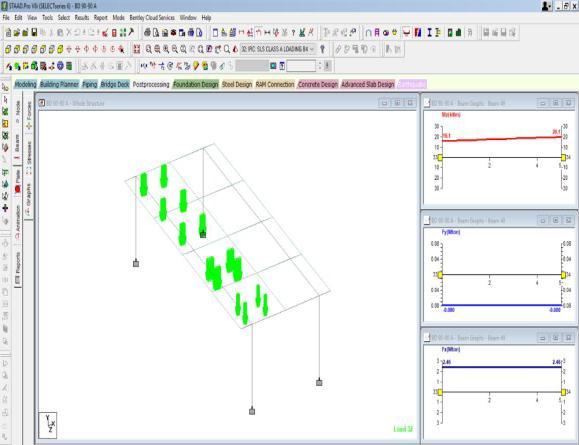
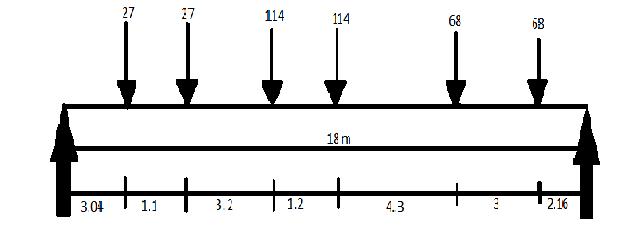
Fig2ArrangementofclassAloadings
Reaction for outer girder=1.83 w1=0.915, reaction for interiorgirder=1.33W1=0.667W
The absolute maximum bending moment always occurs underthewheelloadandnotinbetweenthewheelload is occur at a section near the center of span under the heavier load which is near the center of gravity of the loadingsystemconsider
Totalofload=27+27+114+114+68+68=418,x=6.42m
The c.g of the loading lies at a distance of 6.42 91.1+3.2+1.20=0.92,impactfactor=4.5/(6+18)=0.1875
B.Mduetoliveload(27*1.59)+(27*1.64)+(114*3.325) +(114*4.48)+(68*2.20)+(68*0.70)=1174.18
B.M of outer girder=0.915*1.19*1174.18=1278.50kn*m, B.Mforinnergirder=0.667*1.19*1174.18=931.98
Total max B.M moment (dl=ll) = 1278.50+1784.38=3062kn*m
Reaction on outer girder w1= (114*1.9)/3=72.2kn, w2= (114*0.7)/3=26.6totalw=98.8kn
Reaction on inner girder w1= (114*1.1)/3=41.8, w2= (114*2.3)/3=87.4totalw=129.2kn
Ast = 11100.6, 10 number diameter 40mm, stirrups=10mm @250 c/c spacing provided at support, andatcenter10mm@300mmc/cspacing.
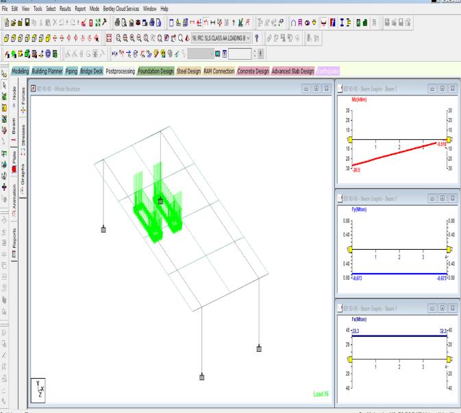
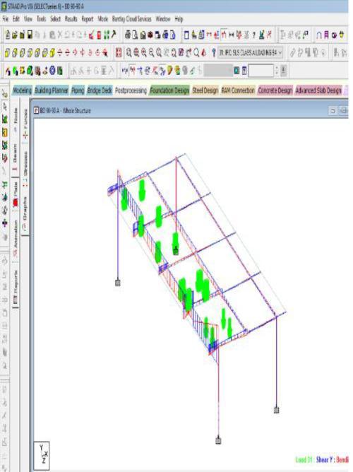
Fig3ClassAloadinginstaadpro
e ISSN: 2395 0056
p-ISSN: 2395-0072
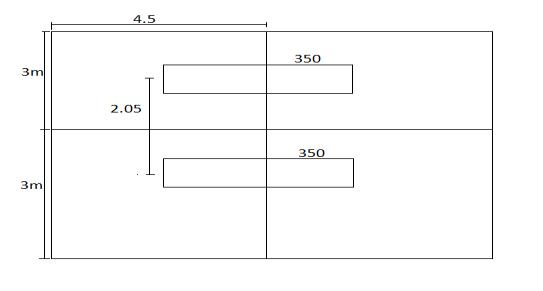
Fig4DesignofcrossgirderforclassAAtrackedloading
Totaldlonslab=23.638kn/m
As an approximate the reaction on each girder is given by,=(23.638*6)/3=47.28
Live load bending moment and shear force for class AA loadingoccurforthepositionoftheloadasshowninfig
The maximum load transfer to the cross girders= (350*2.1)/3=245, assuming equal reaction on each girder=(245*2)/3=163.33kn
Live load shear force =1.1*163.33=179.66, max B.M due toL.L=354.83,maxB.MduetoD.L=47.27
Design B.M =402.10kn*m, design shear force= 226.93knm
Area of steel = 1557.92, 5 number 20mm diameter, stirrups10mmdiameter@300mmc/cspacing
3.2 Design of kerb:
As the kerb is also a part of the deck slab the vehicular load will have influence in generating B.M in the kerb this bending moment is normally taken as 50% of the liveloadobtainedfortheslab.
Totaldeadloadonkerb=8.2
Bendingmomentduetodeadload=22.68
Bendingmomentfromslab=51.95*0.5=25.975
Designmoment(dl+ll)=48.655kn.m,safeindepth
Area of steel: 487mm^2, 3numbers, diameter 16mm, stirrups8mm @300c/cspacing
3.3 RESULTS AND DISCUSSION:
TheoutputdatafortheIRCClassAAtrackedandclassA loadings are considered from staad pro which include, nodaldisplacementsummary,beamendforcesummary, reactionsummary,axialforces,beammoments,liveload effectandmanymoreeffectareconsiderbystaadPro.As per IRC 6 2016 bridge design for class AA loadings shouldbecheckedforclassAloadingsalsoasitisfound thatundercertaincases heavierstressmayoccurunder class A loadings. And as given in IRC 6 2016 for class A loading that this type of loading is adopted on all roads inwhichpermanentbridgeareconstructed.
Research Journal of Engineering and Technology (IRJET)
Volume: 09 Issue: 04 | Apr 2022 www.irjet.net
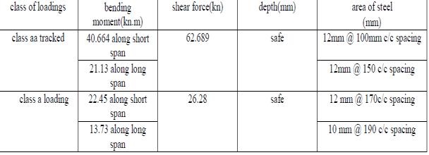
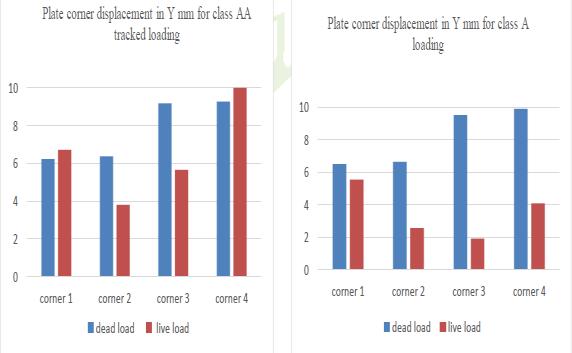
3.4 Result of deck slab panel:
e ISSN: 2395 0056
p-ISSN: 2395-0072
Fig5Staadproresultinmaximumplatecorner displacementYmm
Slab bending moment and shear force result
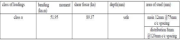
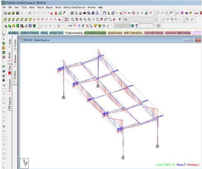
FIG6Bendingmomentandshearforceduetodeadload
FIG7LiveloadclassAAtrackedloadingbending momentandshearforce
As the result are showing that the heavier stress is develop in class AA tracked loading, the depth in both thetypeofloadingissafe.
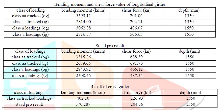
3.5 Result of longitudinal girder:
2022,
Factor value: 7.529 |
FIG8LiveloadclassAloadingbendingmomentand shearforce
9001:2008
Journal |
1240
of Engineering and Technology (IRJET)
Volume: 09 Issue: 04 | Apr 2022
www.irjet.net
e ISSN: 2395 0056
p-ISSN: 2395-0072
will be utilized for higher range, and use for two way piece too. The staad star result almost arrives at the qualitiesgot bycourbon'sstrategyforclassAAfollowed vehicleandforclassAstacking,forclassAATrackedand class A loadings the staad expert outcome is diminished by 5% to 10% when contrasted with courbon's technique.
REFERENCES
[1] Blanchard. J, Davies B L, Smith J W, “Design Criteria And Analysis For Dynamic Loading Of Footbridges” p. 90 106,date 1977 5 19.
[2] Ron Dennis, Rural Accessibility Footpaths and Tracks. A field manual for their construction and improvement,ILOGeneva,2002.
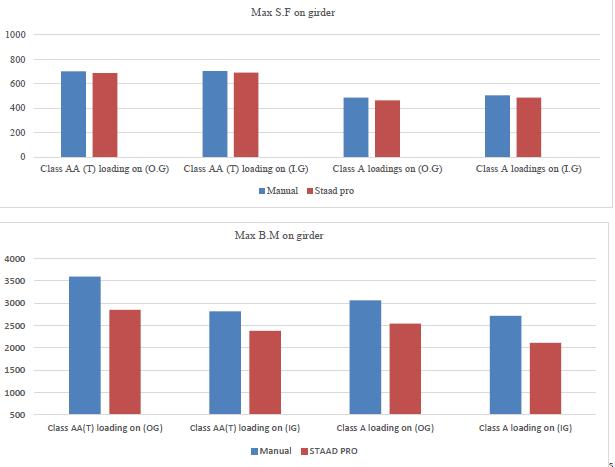
In this project the analysis and design of Bending Moment and Shear force has been studied. from above graphs results of bending moment and shear force are comparedbymanualandSTADDPro.Itisalsoobserved that the density of concrete taken in the STAAD pro is 24kn/m^3, where the density of concrete taken manuallyis25kn/m^3.
CONCLUSIONS
The predefined support and separating for the bridge will be sort out by investigation the worth from staadpro.Thiswillgivethewholereviewandconductof bridgeStructureundervariousIRCloadingsconditionon staadpro. The product are exceptionally useful for developingthemonetarilybridgestructure.It'sseenthat theplancombinationofcementtakeninthestaadexpert is M30, physically plan by M35.Maximum BM happens inside the class AA Tracked stacking vehicle so this stacking is the most pivotal case for greatest BM in longitudinal support. The bowing second worth happen intheexternalsupportisoverthetwistingsecondworth happeninsidetheinternalbrace.Theshearforceesteem happen inside the internal brace is more than the shear force esteem inside the external support. Greatest SF happens for class AA Tracked vehicle stacking so class AATrackedvehiclestackingcaseisthemosturgentcase foridealShearforceinlongitudinalbrace.
Inside the plan of piece board, Maximum shear force and the greatest twisting second worth happen in the in the class AA followed stacking thus class AA followedvehiclecaseisthemosturgentcaseintheterm ofgreatestshearpowerandbowingsecond.Asindicated by the courbon's technique, the absolute best significance given to the Outer Girder and Second for Inner Girder. Here we will plainly see the impact of the pigeauds strategy over the compelling width technique inside the chunk board where the pigeauds technique
[3]Dr.S.V.Itti,andAmarR.Chougule,Professor,M Tech. Student,Dept.ofCivilEngg,KLESCETBelgaum.
[4] BS5400, Part 2, Appendix C, Vibration Serviceability Requirements for Foot and Cycle Track Bridges. British StandardsInstitution,1978
[5] DIN Fachbericht 102, Betonbrücken. DeutschesInstitutfürNormung,2003.
AUTHORS
1.J.HARSHAVARDHAN M.TechScholar CIVILEngineering, SSSISE,ANANTAPUR.
2.C.RUKMUNNISASULTHANA, AssistantProfessor, CIVILEngineering, SSSISE,ANANTAPUR.
3 C.NAGARJUNA AssistantProfessor, CIVILEngineering, SSSISE,ANANTAPUR.