09 Issue:
www.irjet.net

Technology (IRJET)
e ISSN: 2395 0056
ISSN: 2395 0072
09 Issue:
www.irjet.net
Technology (IRJET)
e ISSN: 2395 0056
ISSN: 2395 0072
1P.G. Student, Department of Civil Engineering, Saraswati College of Engineering, Kharghar, Navi Mumbai, India
2Associate Professor, Department of Civil Engineering, Saraswati College of Engineering, Kharghar, Navi Mumbai, India
***
Abstract Skew Bridges are the most required type of bridge but always evaded due to their complex analysis and design, as even in the Indian Standard it didn’t have any specific clause regarding this type of bridge. Mostly, engineers adapt and design a skew bridge as a straight bridge on a field. This paper presents a parametric study on the behaviour of skewness on PSC Box Girder Bridge. The Maximum Shear Force, Bending Moment, Torsion Moment and Displacement under Dead Load and IRC Class A Vehicle load are evaluated, using the finite element based software CSi Bridge v22. In total, 50 bridge models are considered for the present study. The impact of different parameters is calculated. As geometry is considered, then Trapezoidal Sections are more efficient than the Rectangular. Skewness of a bridge affects insignificantly on 10° and 20° bridges, but bridgeswithhigher degree skew angle requires careful in depth analysis. Shear Force decreases insignificantly as the skew angle increases. The hogging bending moment in the skew bridge increases, where the sagging moment decreases as the skew angle increases. Torsion is the biggest factor as it changes radically as the skew angle increases. In 2 and 3 Span bridges, the bending moment suddenly changesat60°. Intheskewbridgea displacement is less than the straight bridge.

Key Words: Skew Angle, Box Girder Bridge, Bending Moment,ShearForce,Torsion,Displacement,FiniteElement Method.
The easiest and shortest route of transportation is requiredfortheidealtrafficflow.Forthat,itisrequiredto cross various obstacles and barriers. Bridges are used to avoidtheseground basedobstaclesandcut shortlongroute toshort.TheBoxGirderBridgesectionisthemostusedbut verycomplexthanthenormalgirderbridge.AsBoxGirder Bridge is efficient in terms of economy and structural functionnowadaysengineerspreferthisbridgesection.For thefastestrouterequiresasimplealignmentwithoutcurves and turns, but sometimes cross alignment is not perpendicular to the road alignment, in that case Skew Bridgesareconsidered.Skewbridgesare verycomplexto analysisanddesign.Theroadalignmentandcrossobstacle alignment coincide with each other, other than the right angle is known as Skew Angle. Most engineers design the skewangleupto20°asthestraightbridge.
Factor
Preeti A. et al. (2019) This paper presents a study on simply supported, single cell, skew reinforced cement concretebox girderbridge.Themaximumbendingmoment and maximum shear force in interior and exterior girders under the IRC class A wheel load are evaluated, using the finiteelement basedsoftwareSAP2000v.14.0.0.Intotal,56 bridge models are considered for investigation. A convergencestudyiscarriedoutonbridgemodeltoselect theappropriatemeshsizeforensuringthereliableresults. The influence of the identified design parameters is investigated. The presence of skew angle reduces the bendingmomentandincreasestheshearforceinboththe girders.[12]
Nidhi G. et al. (2019) AnalysisofRCCboxgirderbridgeis carriedoutforthreedifferentboxgirdersections,i.e.single, double and triple cells using finite element technique by linearstaticmethodofanalysis.Bridgemodelsarestudied with the variation of degree of curvature, which is varied from0°to60°atanintervalof6°.Loadcasesconsideredare deadloadandliveloadconformingtoIndianRoadCongress (IRC).Thevariationofbendingmoment,torsionalmoment, shearforceanddeflectionisstudiedwhicharefoundtobe increased with curvature. It has been estimated that the increased deflection in single, double and triple cell box girderbridgesisabout295%,280%and245%,respectively, inbetween0°(straight)and60°curvedbridges.Thisstudy statesthatthedesignofcurvedbridgesisnotasimpletask whichneedstobeperformedwithutmostcare.[11]
9001:2008
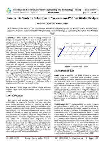
Figure 1 : SkewBridgeLayoutResearch Journal of Engineering and Technology (IRJET)
Volume: 09 Issue: 04 | April 2022 www.irjet.net
Praveen N. et al. (2018) Theyinvestigatedtheinfluenceof skewangleaswellasotherdesignparameters.Followingare theconclusionsmadefromthestudy, forsaggingmoment underdead&movingloadsthebendingmomentincreases with increase in skew angle. For hogging moment under dead load, the bending moment reduces with increase in skewanglebutitrisesundermovingloadwithincreasein skewangle.Underdeadloadtheshearforcereduceswith rise in skew angle & under moving load the shear force increaseswithriseinskewangle.Underdeadload&under movingloadtorsionalmomentincreaseswithriseinskew angle.TheyusedSAP2000withIRCClassAALoading.[10]
Tanmay G. et al. (2017) Several experimental and numericalstudieshavebeenmadetoexaminetheeffectof skewnessonthestructuralresponseofbox girderbridges subjectedtostaticand/ordynamicloads.Theaimoftheir researchtoreviewtheliteraturepublishedonthestructural behavior of skew box girder bridges subjected to static & dynamicloadsincludingseismiceffects.Moreover,thisstudy also reviews the effect of skewness on load distribution among the multi spine/cell box girders bridges and presence of diaphragms in the bridge. According to their result,Bridgeswithskewanglelowerthan20°aresimple enough to design by few modifications in right bridge guidelines, however, for bridges with high skew angle a carefulin depthanalysisisneeded.Verylongbridgestendto negatetheskeweffectbutinshortbridgeshighskewangle can generate a variety of extra forces which must be accountedinwhiledesigning.[9]
Bhalani R. and, Dipak J. (2016) They performed parametric study on effect of curvature and skew on box typebridge.Astaticanalysisfordeadloadandmovingload and a model analysis performed. Results states that by increasing radius of curvature for same skew angle, time period is decrease. So that time period value is more compare to straight bridge, also by increasing radius of curvature for same skew angle, value of deflection is decrease. So that deflection is more in curved bridge. As increasing value of radius of curvature, value of bending momentisalsodecreaseindeadloadplussuperdeadload andmovingloadcase.[7]
Shrikant B. and Dr. Valsson V. (2016) presents comparative study based on the analytical modeling of simply supported RC Box Girder Bridge for various Skew anglesusingStaadPro.BasedonthisstudyDeflectionoccurs forLiveLoadCombinationcase IIofvariousSkewangles resultisincreaseby(1.750%)withincreaseinSkewangle are compared. Bending moment occurs for Live Load Combination case II of various Skew angles result is increase by (1.525%) with increase in Skew angle are compared. Shear force occurs for Live Load Combination case II of various Skew angles result is increase by (1.376%) with increase in Skew angle are compared. TorsionalMomentoccursforLiveLoadCombinationcase II
Factor value:
e ISSN: 2395 0056
p ISSN: 2395 0072
ofvariousSkewanglesresultisincreaseby(135.36%)with increase in Skew angle are compared. Support Reaction occursforLiveLoadCombinationcase IIofvariousSkew anglesresultisincreaseby(0.001%)withincreaseinSkew anglearecompared.[8]
Pranathi R. and Karuna S. (2015) presentscomparative study on normal and skew bridge of PSC box girder performed.Afiniteelementanalysisperformedtoconclude thatmagnitudeofshearforcereducedwithincreaseinskew angle under dead load in multi span deck where in single span shear force remained same in all models compared with straight deck under dead load. So no. of span also affectstheskewbridges.Bendingmomenthasreducedwith increaseinskewangleunderdeadloadinsingle,twoand three spans deck. But under moving load there is slight reductioninbendingmomentupto20°andthenincreased for30°andfurtherreducedfor40°skewangleonlyonsingle spandeck.[5]
Sujith P. S. et al. (2015) Theobjectiveoftheprojectwasto comparefiniteelementmethodandgrillagemethod.Itcan beconcludedthatanalysisbyusingfiniteelementmethod gives more economical design when compared with the grillage analysis. With increase in the skew angle, the stresses in the slab differ significantly from those in a straightslab.Reactionincreasedwithincreasingskewangle. Finite element method gives more economical design and accuratewhencomparedwiththegrillageanalysis.Upliftor negative reaction at the acute corner. Maximum or high reactionattheobtusecorner.[6]
Aim:
The aim of this study is to analyze the different parametersofPSCBoxgirderbridgestovariationinitsskew anglefrom0°to60°withanintervalof10°,withdifferent loading,no.oflanes,no.ofcells,no.ofspanwhichshowsthe behaviourofslabwithforcesandmoments.
ToconductparametriccomparisonofRectangular andTrapezoidalBoxGirderBridgedeck.
To conduct the analysis of PSC box girder bridge withdifferentskewanglefrom0°to60°.
Tostudytheeffectofdifferentloads.
Tocomparethevariationinmaximumshearforces andbendingmomentsfordifferentskewanglefrom 0to60degreeunderdeadloadandIRCloading.
To understand effect of Torsion moment in skew bridges.
Tostudytheeffectofspanlength,no.oflanesand no.ofspanwithrespecttoforcesandmoments.
Tounderstanddisplacementinallmodelledbridge.
| ISO 9001:2008
and
Volume: 09 Issue: 04 | April 2022 www.irjet.net
Togenerategraphicalchartsbasedonabovestudy, which could simplify to understand behaviour of skewbridges.
Total50bridgesareanalyzedtofindoutthebehaviourof skewnessonbridgesectionusingCSiBridgesoftware.The skew angle of the bridges varies from 0°, 10°, 20°, 30°, 40°,50° and 60°. No. of lanes and spans are varying to determinebehaviourofskewnessonbridgewithdifferent parameters.Prestresstendonsareconfiguredonthemodel basedonprestressingdone ontheexistingbridgeasbuilt drawing. The IRC Load specified in IRC 6 2016, Class A vehicleisusedforliveloadloading.
The bridges under this study are simply supported bridges.Followingbridgesaremodelledandanalyzedfrom 0°to60° No.ofLanesinTwoCellbridgesare3:
TwoCellTrapezoidalboxgirder25mspanlength havingsinglespan.
TwoCellTrapezoidalboxgirder40mspanlength havingsinglespan.
TwoCellRectangularboxgirder50mspanlength havingsinglespan.
TwoCellTrapezoidalboxgirder50mspanlength havingsinglespan.
TwoCellTrapezoidalboxgirder50mspanlength having2spans.
SingleCell(2Lanes)Trapezoidalboxgirder50m spanlengthhavingsinglespan.
Three Cell (4 lanes) Trapezoidal box girder 50 m spanlengthhavingsinglespan.
TwoCellTrapezoidalboxgirder75mspanlength having3spans.
Thecarriagewaywidthisdependedupontheno.ofcells. A box girder bridge consists of a top and bottom slab connected by vertical webs to form a cellular or box like structure.Thicknessofthewebis300mm.Topandbottom widthofslabis240mm.Theoveralldepthofthesectionis 2.5m.
The geometry of the models is based on the Gadi River bridge constructed as part of NH348 (JNPT National Highway). Their dimensions are modified to satisfy structural design provisions. Following are the material properties,fromthereferenceofIndianStandardsandfrom availabledrawingofthebridge:
1)Gradeofconcrete=M45=45N/mm²
2)Young'smodulus(E)=3.35�10·kN/m²
3)Poisson'sratio(υ)=0.2
e ISSN: 2395 0056
p ISSN: 2395 0072
4)ShearModulus(G)=1.39�10·kN/m²
5)Coefficientofthermalexpansion(A)=5.5�10ˉ
6)Specificcomp.strengthofconcrete(fc’)=45kN/m
1)Typeofpre stressing Posttensioning
2)Diameterofthepre stressingcable=ASTM0.5
3)Pre stressingStrand=13mm(0.5”strand)
4)ModulusofElasticity=Eps=1.968�10¸kN/m²
5)Elasticshorteningstress=20684.274kN/m²
6)Creepstress=34473.79kN/m²
7)Shrinkagestress=48263.31kN/m²
8)Steelrelaxationstress=34473.79kN/m²
9)Curvaturecoefficient=0.15
10)Wobblecoefficient=6.56�10ˉ´
11)AnchorageSlip=6.35�10ˉ³m
12)Coefficientofthermalexpansion(A)=1.17�10ˉµ
13)Minimumyieldstress=Fy=1689.9�10³kN/m²
14)Minimumtensilestress=Fu=1861.58�10³kN/m²
1)Gradeofsteel=HYSD500=500N/mm²
2)Young'smodulus(E)=2.00�10¸kN/m²
3)Poisson'sratio(υ)=0.3
4)Coefficientofthermalexpansion(A)=1.17�10ˉµ
5)Minimumyieldstress=Fy=5�10µkN/m²
6)Minimumtensilestress=Fu=5.45�10µkN/m²
1. Dead Load:Self weightofthemodelwasnottakenasa lumpofmass.Rather,alltheelementsuchasshellorsolid elements are loaded by gravity load. Thus, self weight is accountedforinthemodelautomatically.Additionally,load duetowearingcourseistaken1.4364kN/m²inthisstudy. Also,loadduetocrashbarriersistakenas5.1079kN/mat twosidesofthedeck.
2. Live Load:ForallbridgesClassAtypevehicleloadingis consider.Thistypeofvehicleloadingisusedinthedesignof allpermanentbridges.Itisconsideredasstandardliveload ofbridge.GreaterstressesareattainedunderclassAloading. ClassAloadingincludesofawheelloadtraininclusiveofa driving vehicle and two trailers of specified axle spacings.[23]
Factor value:
9001:2008
09
and Technology (IRJET)
www.irjet.net
Figure 2 : ClassAVehicle(IRC6:2016Clause204.1) pg.no.12
Thefiniteelementmethodisthemostpowerfultechnique of analysis arising from the direct stiffness method. Sienkiewicz, Desai Abel and Martin Carey did revolutionaryworkinthisfield.Finiteelementanalysis,also calledthefiniteelementmethod,isamethodfornumerical solutionoffieldproblems.Finiteelementanalysisinvolves lot of numerical calculations. Hence it is not a suitable methodforhandcalculations.Themethodisideallysuited for computer applications and has developed along with developmentsincomputertechnology.Inengineeringthis methodusedfortheanalysisofbeams.spaceframes,plates, shells,foldedplates,foundations,rockmechanicsproblems. Bothstaticanddynamicproblemscanbehandledbyfinite element analysis. This method is used extensively for the complexstructurelikeanalysisanddesignofships.aircrafts, spacecrafts,electricmotorsandheatengines.[18][19]
FiniteElementAnalysisinvolvesdifferentstages:Tosolve problem suitable field variables and the elements are selected then separate the sequences. After that select interpolationfunctionthenfindpropertiesoftheelement. Accumulate element properties to get global properties. Applythe boundaryconditions,to get the nodal unknown solve the system equation and to get the required value makethesupplementarycalculations.[20]
e ISSN: 2395 0056
p ISSN: 2395 0072
Inordertoachievementionedobjectivesforthistypeof bridges,thescopeofthisstudyisasfollows:
•ThemethodtoanalyzebridgesisFiniteElementMethod.
•AnalysisofFEMmodel ofboxgirderbridgebyusing CSi Bridgev22software.
• The models are for different skew angle i.e. from zero degreeto60degreewithanintervalof10degree.
•TheboxgirderbridgesanalyzedonlyforDeadLoadand LiveLoad.IRCClassAVehicleusedforliveloadloading.
• The self weight is applied by CSi Bridge with density of concrete taken as 25 kN/m³. The length is mentioned in Meter(m),theforcesarementionedinKiloNewton(kN),the momentsarementionedinKiloNewtonMeter(kN.m)and VerticalDisplacementarementionedinMillimeter(mm).
•TheguidelineforloadingasperIRCCodes.
• The carriageway width of varies for all bridges depend upontheno.ofboxcells.
•Thedeckofthebridgessupportedbyrollingsupports at each end. These supports prevent translation only perpendicular to the deck surface (i.e., in the Z direction). Therefore, in all models the two corners of the deck are restrained against the X and Y directions to prevent instabilityofthedecks.
• The analysis has been carried out for the mentioned loading and the results are obtained for Shear Force, HoggingandSaggingBendingMoment,TorsionMomentand VerticalDisplacement.
• After this parametric study of different skewed bridges done,concludingremarkspreparedaftercomparativestudy.
Thestructuresunderconsiderationaresimplysupported box girder bridges. The loads have been categorized into followingparts:

1. Dead Load (Self weight + Wearing Course + Crash Barriers)
2. Live Load (IRCClassAVehicle)
CSi Bridge: Modelling, analysis, and style of bridge structures are combined into CSi Bridge to form the final wordincomputerizedtoolsmodifiedtosatisfythewantsof theengineeringskilled.thesuitabilitywiththatallofthose tasksisskilledmakesCSiBridgetheprimaryadaptableand productive package program within the trade. After modelling,CSiBridgeprovideschoicesfortheassignmentof load cases and combos. Vehicle loading are generated consistent with codification (AASHTO LRFD, Canadian, Indian etc.) and assigned consistent with model pure mathematics.Aseriesoftemplatesforassignmentandclose loadconditionscreateCSiBridgeintuitiveandsensible.once thefirstobject basedmodelhasbeentranslatedintoafinite elementmodelandsubjectedtoloadcasesandcombos,the analysismethodfollowsdirectly.[16]
Todeterminethesectionofboxgirderforfurtherstudy, comparative study of Rectangular and Trapezoidal Girder bridge.[14]
Figure
ISSN: 2395 0056
Table 1: ComparisonbetweenRectangularand TrapezoidalSection
Rectangle Trapezoid DL+LL DL+LL

ShearForce(kN) 6113.49 5898.02
Hogging Bending Moment (kN.m) 15157.92 18024.93
Sagging Bending Moment (kN.m) 58828.50 52918.72

TorsionMoment(kN.m) 1866.12 1850.73
Displacement(mm) 56.79 55.49
Cross SectionalArea(m²) 6.35 5.99
From the results obtained from the analysis following conclusionsaredrawn
1) Central deflection in rectangular section is higher thanthatoftrapezoidalsection.
2) Shear force and Bending Moment is more in the rectangularsection.
3) Torsioneffectisinsignificant.
4) Withsamespecificationofslabwidth,carriageway, girder width Trapezoidal Section area is less than the rectangularsection.


5) Hence,Consumptionofconcreteandsteelismorein rectangularsectionthanintrapezoidalsection.
6) Use of the trapezoidal section will increase the aestheticappearanceofthebridge.
From above comparison, all model sections modeled in TrapezoidalSection
As literature survey suggest with skew angle geometry of bridgesectionalsoaffecttheresult.Tounderstandtheeffect ofdifferentparameters,followingparametersareconsidered forthisstudy:SpanLength,No.ofSpanandNo.ofLanes.For Span Length are 25m, 40m and 50m are considered for comparativestudy.ForNo.ofSpanSingleSpanBridge,Two SpanBridgeandThreeSpanBridgeareconsideredwithspan lengthof25m,50mand75mrespectively.ForNo.ofLanes2 Lanes,3Lanesand4Lanesareconsideredwithsinglecell box girder, two cell box girder and three cell box girders respectively.
To study the effect of span length, three different spans considered25m,40mand50mrespectively.
Shear Force
Table 2: EffectofSpanLengthonSkewBridgeduetoShear Force
Skew Angle
Figure
ShearForce(kN) 25mSpan 40mSpan 50mSpan DL+LL DL+LL DL+
Figure Figure ElementModelinCSiof Engineering and Technology (IRJET)
Volume: 09 Issue: 04 | April 2022 www.irjet.net
0° 3397 4895 5898.3
10° 3383 4888 5896.9
20° 3370 4886 5895
30° 3350 4876 5884.5
40° 3330 4869 5873.6
50° 3301 4857 5856.6
60° 3294 4843 5843.5
Figure 7: EffectofSpanLengthonSkewBridgedueto ShearForce Bending Moment


Table 3: EffectofSpanLengthonSkewBridgedueto HoggingBendingMoment
Skew Angle HoggingBendingMoment(kN.m)
25mSpan 40mSpan 50mSpan DL+LL DL+LL DL+LL
0° 4394.61 11705 18024.9
10° 4546.23 11917 18336.1
20° 4755.31 12426 19142.4
30° 5244.84 13623 20940.7
40° 6340.64 15946 24308.2
50° 7678.71 18928 28742.8
60° 9046.62 21981 33419.5
e ISSN: 2395 0056
p ISSN: 2395 0072
value:
3000 9000 15000 21000 27000 33000
Hogging Moment Skew Angle 25m 40m 50m
0° 10° 20° 30° 40° 50° 60°
Figure 8: EffectofSpanLengthonSkewBridgedueto HoggingBendingMoment
Table 4: EffectofSpanLengthonSkewBridgeduetoSagging BendingMoment
Skew Angle
SaggingBendingMoment(kN.m)
25mSpan 40mSpan 50mSpan DL+LL DL+LL DL+LL
0° 15006 35552 52918.7
10° 14945 35439 52688.9
20° 14777 34998 51915
30° 14317 33838 50117.4
40° 13224 31514 46763.8 50° 11759 28399 42252.2 60° 13561 24815 37079.2
Figure 9: EffectofSpanLengthonSkewBridgedueto SaggingBendingMoment
9001:2008
Table 5: EffectofSpanLengthonSkewBridgedueto TorsionMoment
Skew Angle TorsionMoment(kN.m)
25mSpan 40mSpan 50mSpan DL+LL DL+LL DL+LL
0° 1534.57 1738.12 1850.73
10° 2648.17 4137.81 5468.96
20° 3878.21 6915.32 9508.08
30° 5095.68 9571.84 13280.64
40° 6272.4 11847.67 16544.99
50° 7062.27 13247.05 18450.33 60° 4699.25 13477.55 18582.34
Figure 10: EffectofSpanLengthonSkewBridgedueto TorsionMoment
Table 6: EffectofSpanLengthonSkewBridgedueto
Skew Angle VerticalDisplacementinmm 25mSpan 40mSpan 50mSpan
0° 4.1721 23.79 55.49
10° 4.1449 23.68 55.19
20° 4.1012 23.30 54.18
30° 3.9745 22.30 51.756
40° 3.6603 20.35 47.18
50° 3.2556 17.75 41.04 60° 2.9886 14.79 34.08
ISSN:
0056
As we know shear force decreases as the skew angle increases, but in longer span decrement is less than 1 % whereinshorterspanitismorethan3%.Hoggingmoment incrementismoreinshortspanbridge.Asobservedinthe tablein25mspanbridgeHoggingMomentincreasesupto 105%ascompareto40mand50mbridgehavingalmost87% and85%respectively,whereinsaggingmomentdecrement islessinshortspanbridge.Torsionmomentincreasesasthe skewangleincreases,significantincrementinlongerspan.In 25mspanbridgeitincreasesmaximumin50°bridgeupto 360%ascomparetostraightbridge,whereinotherbridges torsionincreasesin60°upto675%and904%in40mand 50m respectively. As table suggest in short span vertical displacement is less, also as the skew angle increases displacementdecreases.


Table 7: EffectofNo.ofSpanonSkewBridgeduetoShear
Skew Angle ShearForce(kN)
Single Span
Span
0° 3397 3851 3803
10° 3383 3841 3799
3370 3824 3789
3350 3788 3776
40° 3330 3717 3756
3301 3627 3738
3294 3475 3684
Engineering and Technology (IRJET)
Volume: 09 Issue: 04 | April 2022 www.irjet.net
Figure 12: EffectofNo.ofSpanonSkewBridgedueto
Table 8: EffectofNo.ofSpanonSkewBridgeduetoHogging
Skew Angle HoggingBendingMoment(kN.m)
SingleSpan 2Span 3Span DL+LL DL+LL DL+LL
0° 4394.61 14869 13488
10° 4546.23 15004 13691
20° 4755.31 14990 13931
30° 5244.84 14648 14231
40° 6340.64 13739 14610
50° 7678.71 12340 14774
60° 9046.62 10585 14156
Figure 13: EffectofNo.ofSpanonSkewBridgedueto HoggingBendingMoment
Factor value:
e ISSN: 2395 0056
ISSN: 2395 0072
Table 9: EffectofNo.ofSpanonSkewBridgedueto SaggingBendingMoment
Skew Angle SaggingBendingMoment(kN.m)

SingleSpan 2Span 3Span DL+LL DL+LL DL+LL
0° 15006 12205 12954
10° 14945 12139 12901
20° 14777 12020 12748
30° 14317 11894 12582
40° 13224 11791 12478 50° 11759 11522 12235 60° 13561 14344 15105
Figure 14: EffectofNo.ofSpanonSkewBridgedueto SaggingBendingMoment
Torsion Moment
Table 10: EffectofNo.ofSpanonSkewBridgedueto TorsionMoment
Skew Angle TorsionMoment(kN.m)

SingleSpan 2Span 3Span DL+LL DL+LL DL+LL

0° 1534.57 1626.46 1660.74
10° 2648.17 2185.55 2264.72
20° 3878.21 2775.33 2927.33
30° 5095.68 3426.07 3651.69
40° 6272.4 4221.3 4425.29
50° 7062.27 5199.99 5138.05 60° 4699.25 3908.78 3231.3
9001:2008 Certified Journal
Research Journal of Engineering and Technology (IRJET)
Volume: 09 Issue: 04 | April 2022 www.irjet.net
Figure 15: EffectofNo.ofSpanonSkewBridgedueto TorsionMoment
Displacement
Table 11: Effect of No. of Span on Skew Bridge due to Displacement


Skew Angle VerticalDisplacementinmm SingleSpan 2Span 3Span
0° 4.1721 3.1169 3.4506
10° 4.1449 3.0884 3.4279
20° 4.1012 3.0959 3.4141
30° 3.9745 3.1899 3.4774
40° 3.6603 3.4535 3.7180
50° 3.2556 3.7117 3.9787
60° 2.9886 3.9942 4.0812
Figure 16: EffectofNo.ofSpanonSkewBridgedueto Displacement
2022,
e ISSN: 2395 0056
p ISSN: 2395 0072
As we know shear force increment is insignificant. HoggingmomentDecrementin2spanbridge,ascompareto incrementinotherbridges.For2and3spanbridgeSagging Moment increases at 60° after reducing till 50°. Torsion momenthereincreasestill50°astheskewangleincreases, butthendecreasesat60°.Asthesebridgesarewithshorter spanverticaldisplacementisveryless.

Table 12: EffectofNo.ofLanesonSkewBridgedueto ShearForce
Skew Angle
ShearForce(kN)
2Lane 3Lane 4Lane
DL+LL DL+LL DL+LL
0° 4239 5898.3 7942
10° 4243 5896.9 7944
20° 4240 5895 7936
30° 4246 5884.5 7923
40° 4240 5873.6 7921
50° 4236 5856.6 7907
60° 4223 5843.5 7863
Factor value:
Figure 17: EffectofNo.ofLanesonSkewBridgedueto ShearForce
9001:2008
of Engineering and Technology (IRJET)
Volume: 09 Issue: 04 | April 2022 www.irjet.net
Table 13: EffectofNo.ofLanesonSkewBridgedueto HoggingBendingMoment
Skew Angle
HoggingBendingMoment(kN.m)
SingleSpan 2Span 3Span DL+LL DL+LL DL+LL
0° 13626 18025 9782
10° 13885 18336 11176
20° 14810 19142 14749
30° 15620 20941 20995
40° 17244 24308 30907
50° 20037 28743 38646
60° 23714 33420 42465
3000 10000 17000 24000 31000 38000 45000
Hogging Moment Skew Angle
0° 10° 20° 30° 40° 50° 60°
2Lane 3Lane 4Lane
Figure 18: EffectofNo.ofLanesonSkewBridgedueto HoggingBendingMoment
Table 14: EffectofNo.ofLanesonSkewBridgedueto SaggingBendingMoment
Skew Angle SaggingBendingMoment(kN.m)
SingleSpan 2Span 3Span DL+LL DL+LL DL+LL
0° 37082 52919 86390
10° 36907 52689 85085
20° 36045 51915 81624
30° 35284 50117 75518
Sagging Moment
25000 35000 45000 55000 65000 75000 85000
e ISSN: 2395 0056
p ISSN: 2395 0072
0° 10° 20° 30° 40° 50° 60°
Skew Angle
2Lane 3Lane 4Lane
Figure 19: EffectofNo.ofLanesonSkewBridgedueto SaggingBendingMoment
Torsion Moment
Table 15: EffectofNo.ofLanesonSkewBridgedueto TorsionMoment
Skew Angle TorsionMoment(kN.m)
2Lane 3Lane 4Lane DL+LL DL+LL DL+LL
0° 1095.4 1850.73 3246.75 10° 3163.1 5468.96 11359.25
20° 5466.8 9508.08 19166.54
30° 7641.36 13280.64 25746.26
40° 9794.69 16544.99 28299.23 50° 11502.15 18450.33 29312.97 60° 12304.97 18582.34 29720.76
Torsion Moment
0 6000 12000 18000 24000 30000
International Research Journal Skew Angle
0° 10° 20° 30° 40° 50° 60°
40° 33721 46764 65578
50° 30972 42252 57243
60° 27198 37079 51842
© 2022, IRJET | Impact 2Lane 3Lane 4Lane
Factor value: 7.529 | ISO 9001:2008
Certified Journal | Page1149 Figure 20: EffectofNo.ofLanesonSkewBridgedueto TorsionMoment
09 Issue:
Table 16: EffectofNo.ofLanesonSkewBridgedueto Displacement
Skew Angle VerticalDisplacementinmm 2Lane 3Lane 4Lane

0° 59.12 55.49 66.20
10° 58.8 55.19 64.95
20° 56.97 54.18 61.72
30° 55.5 51.75 55.74
40° 52.3 47.18 46.46 50° 46.6 41.04 38.74 60° 38.7 34.08 34.07
Figure 21: EffectofNo.ofLanesonSkewBridgedueto Displacement
Shear force remains insignificant as the skew angle increases. Sagging moment is decreases as the skew angle increases,wherehoggingmomentincrementin4lanebridge issignificantlymoreascomparetoothers.Torsionmoment incrementin2lanebridgeismorethanthe4 lanebridge.As these bridges having longer span, vertical displacement is more.
TheeffectonbridgeofDeadLoadandLiveLoadi.e.IRC ClassAvehicleloadingaredifferentforskewedbridge.Inthe presentstudyonthebasisofdifferentparametersfollowing conclusionsaredrawn:
Aliteraturereviewwascompletedinthisstudyto summarizethebehaviourofskewbridges,analysis and research. The study is mainly focused on the bendingmoment,shearforceandTorsionanalysis inskewbridges.
(IRJET)
e ISSN: 2395 0056
ISSN: 2395 0072
As study suggested, three dimensional finite element analysis by CSi Bridge v22 is suitable for assessingthebehaviourofskewbridges.
Trapezoidalboxgirdersectionismoreefficientthan therectangularboxgirdersection.
Bridgeswithskewanglelowerthan20°aresimple enoughtodesignbyfewadjustmentsastheright angle bridge, because skewness of bridge affects insignificantly for 10° and 20° bridges, but for bridges with high skew angle a careful in depth analysisisneeded.
Insignificantreductioninshearforceoccurasthe skewangleincreasesi.e.,asweobservedfrom0°to 60°shearforcedecreasescontinuously.
Hogging bending moment increase and sagging momentdecreasewithincreasinginskewanglefor all types of bridges and in all load case which considerinstudy.
Hogging Bending Moment increment is more in short span, single span and in 4 lane bridges. SaggingBendingMomentdecrementislessinshort spanbridge,morein4lanebridgeandin2&3span bridgesaggingmomentsuddenlyincreasesat60°.
While designing skew bridges, torsion moment shouldbeconsideredasamajorfactor,asobserved in all parameters and in all section’s torsion moment increases immensely as compared to bendingmomentandshearforceastheskewangle increases.Torsionmomentincrementismorein2 lanebridgethan4lanebridge.
As observed in all cases maximum vertical displacementismoreinrightanglebridgethanthe skewedbridge.Also, displacement islessinshort span.
As observed Span Length, No. of Span and No. of Lanesaffectsignificantlyinskewbridges.
Inthepresentworkonlybridgedeckisconsidered, for further research study regarding bearings, bents,piersandothersstructuralcomponentsmay beconsidered.
As we observed short span bridge of box girder showingvariationinratios,studyforsuitabletype ofbridgemayconsidered.
In the present work Dead and Moving Loading is considered, for further research study regarding
9001:2008
International Research Journal of Engineering and Technology (IRJET)
Volume: 09 Issue: 04 | April 2022 www.irjet.net
seismicbehaviourordifferentIRCvehicleloading onskewbridgesmaybeconsider.
A detailed economic analysis of different skew section bridges may be considered to find out necessaryofbridgetypetoconstruct.
TheauthorsacknowledgeDepartmentofCivilEngineering andPrincipalof“SaraswatiCollegeofEngineeringKharghar, NaviMumbai”forvaluableguidance.
[1] BaidarBakht(1988),“AnalysisofSomeSkewBridgesas RightBridges”.JournalofStructuralEngineering(ASCE) Vol.114.
[2] Haoxiong Huang; Harry W. Shenton, M. ASCE; and MichaelJ.Chajes(2004),“LoadDistributionforaHighly SkewedBridge:TestingandAnalysis”.JournalofBridge EngineeringVol.9,Issue6(Nov04).
[3] C. Menassa; M. Mabsout; K. Tarhini; and G. Frederick (2007), “Influence of Skew Angle on Reinforced ConcreteSlabBridges”,JournalofBridgeEngineering, Vol.12,No.2,March1,2007.©ASCE,pp205 214
[4] GholamrezaN.andAhmadiz(2012),“InfluenceofSkew AngleonContinuousCompositeGirderBridge”.Journal ofBridgeEngineering2012,Vol.17,pp.617 623.
[5] PranathiReddy,KarunaS(2015),“Comparativestudy onNormal&SkewPSCBoxGirderBridge”,International JournalofScientific&EngineeringResearch,Volume:4, Issue:6,June2015.
[6] SujithPS,Dr.JijiAnnaVarughese,TennuSyriac(2015), “ComparativeStudyontheBehaviourofT BeamSkew Bridges”InternationalJournalofInnovativeResearchin Science,EngineeringandTechnology,Volume4,Issue9, September 2015.
[7] Mr.BhalaniRaj,Prof.DipakJivani(2016),“Parametric Study on Effect of Curvature and Skew on Box Type Bridge”.©May2016IJSDR|Volume1,Issue5.
[8] Shrikant D. Bobade, Dr. Valsson Varghese (2016), “Parametric study of skew angle on box girder bridge deck.”InternationalJournalofEngineeringSciences& ResearchTechnology,5(7):July,2016.
[9] Tanmay Gupta, Manoj Kumar (2017), “Structural response of concrete skew box girder bridges.” InternationalJournalofBridgeEngineering(IJBE),Vol. 5,No.1,(2017),pp.37 59.
e ISSN: 2395 0056
p ISSN: 2395 0072
[10] Mr. Praveen Naik, Dr. R. Shreedhar (2018), “Study on BehaviourofSkewPSCBoxGirderBridge.”International JournalforResearchinAppliedScience&Engineering Technology(IJRASET)Volume6IssueV,May2018.
[11] Xingwei Xue; Jiawei Wu (2018), “A Finite Segment Method for Skewed Box Girder Analysis.” Hindawi Mathematical Problems in Engineering Volume 2018, ArticleID2592613,13pages.
[12] PreetiAgarwal,P.Pal,P.K.Mehta(2019),“Analysisof RC Skew Box Girder Bridge.” International Journal of Science & Innovative Engineering & Technology, May 2019Volume6.
[13] NidhiGupta,PreetiAgarwal&PriyaranjanPal(2019), “Analysis of RCC Curved Box Girder Bridges.” Applied InnovativeResearchVol.1,September December2019, pp.153 159.
[14] Pragya Soni, Dr. P.S. Bokare (2017), “Parametric ComparisonofRectangularandTrapezoidalBoxGirder BridgeDeckSystem”.InternationalResearchJournalof EngineeringandTechnology,Vol 4,Issue9(Sep2017)
[15] S.S. Bhavikatti, “Finite Element Analysis.”, New Age International(P)Limited,Publishers.
[16] N. Krishna Raju, “Design of Bridges.”, Oxford & IBH PublishingCompanyPvt.Ltd.
[17] BridgeManual,SAP(2000).“LinearandNonlinearStatic andDynamicAnalysisandDesignofThree Dimensional structures.”
[18] A brief overview of Finite Element Method, School of ManagementScience,Lucknow
[19] Computer Aided Analysis & Design of Structures, Ahsanullah University of Science and Technology, 2nd Revision;November2017
[20] IntroductionofFiniteElementAnalysis(FEA)orFinite ElementMethod(FEM),UniversityofVictoria,Canada.
[21] IS456:2000“PlainandReinforcedConcrete Codefor Practice”.
[22] IS 14268 (1995): “Uncoated stress relieved low relaxationseven plystrandforprestressedconcrete”.
[23] IRC:6 2016 “Standard Specifications and Code of Practice for Road Bridges Section: II Loads and Stresses”.
[24] IRC 112 2019: “Code of Practice for Concrete Road Bridges”.
2022, IRJET | Impact Factor value: 7.529 | ISO 9001:2008 Certified
Research Journal of Engineering and Technology (IRJET)
Volume: 09 Issue: 04 | April 2022 www.irjet.net
Pranav K. Mhatre

P.G.Student
Department of Civil Engineering, Saraswati College of Engineering, Kharghar, NaviMumbai,India

AssociateProfessor&HOD
Department of Civil Engineering, Saraswati College of Engineering, Kharghar, NaviMumbai,India
e ISSN: 2395 0056
p ISSN: 2395 0072