Research Journal of Engineering and Technology (IRJET)

Volume: 09 Issue: 04 | Apr 2022 www.irjet.net
e ISSN:2395 0056
p ISSN:2395 0072
Research Journal of Engineering and Technology (IRJET)
Volume: 09 Issue: 04 | Apr 2022 www.irjet.net
e ISSN:2395 0056
p ISSN:2395 0072
***
Abstract A computational fluid dynamics (CFD) analysis is used in this research study to explore the combined impacts of tubercles and dimples on the Wortmann FX 60 126 airfoil. The primary goal of adding TuberclesandDimplestothewingistocreatevorticesby causing turbulence(s) and so delaying boundary layer separation,resultinginadecreaseinpressuredragandarise installangle.Theflowanalysiswasperformedafterthebasic wing was modified with four different variables of wavelengthsandamplitudesfortubercles.Theprecisepoint ofboundarylayerseparationonthetubercleaddedwingwas determined, and semi sphere inward dimples were introducedatthoselocations.Theairfoilwasthentestedwith various angle of attacks (0,5,10,15 and 20)with an inlet velocity of 80m/s and the required results were achieved. This analysis supports the tubercle and dimple effect by increasing the L/D ratio and so achieving optimum aerodynamic efficiency, and thus improving the aircraft performance. The wing withthe wavelengthof 50mmand amplitude of 10mm had produced the better results comparativelytotheotherwings.
these additional wing components on a cambered airfoil. FollowingaGridIndependencestudyandavalidationcase derivedfromexistingresearchpapersonsymmetricalairfoil withtuberclesanddimples, theviscousComputationalFluid Dynamics(CFD)approachwasappliedfortheinvestigations.
Does addition of Tubercles or Dimples improve aircraft performance? For a long time, engineers have been fascinated by bio mimicry, particularly in the field of aeronautics.Aplethoraofresearchhasbeenconductedon how the addition of components such as tubercles on humpbackwhalesandthe semisphereinwarddimplesofa golfballcanbebeneficialforimprovingtheperformanceof theaircraftandtheresultssuggeststhatthetubercle/dimple effect operates by diverting flow over the airfoil into narrowerstreamsbyincreasingvelocitiesand sodelaying boundarylayerseparationandthebrightsideofthisfinding statesthatthisadditionalwingcomponentreducespressure dragbycreatingwingtipvorticesandconsiderablyincreases lift force. Tubercles [3] can stabilize flow by generating vortices,thedragincreasesslightlyinlesschallengingflow conditions.
Ourresearchisbaseduponthecombinedeffectsoftubercles anddimplesonacamberedairfoilandhowthisadditionwill impact the performance of the aircraft. A lot of research papersontubercleordimpleadditiononsymmetricalairfoils areavailablebutourfocusistowardsstudyingtheimpactof
Flowseparationiswhatneedstobeavoidedonanysurface whichissubjectedto airflow.Flowseparationshappendue to change in pressure gradient. The pressure gradient increasesasitmovesalongthesurface,therecomesapoint where the pressure gradient increases drastically. This certain point is the location where the flow starts to separate.ThereasonwhyitshouldbeavoidedisPressure drag.Whentheflowseparatesfromthesurface,itstartsto form low pressure zone. This causes drag, hence called pressuredrag.Flowseparationlimitstheaircraftfromflying athigherangleofattacks.Thiscausesstallingofthewing. Wing modifications can be done to delay flow separation. Tubercles on the leading edge/ trailing edge, Vortex generatorsandupwarddimples/downwarddimplesdelay theflowseparationfromthesurface.Alotofresearchhas beengoingonthesemodifications.Inthisparticularstudy, Tubercles on theleading edgeanddimplesonthesurface havebeenaddedforbetter performance ofthewing.This way,thewingwillbeabletoproducedesiredliftcoefficient valuesathigherangleofattacks.
The viscosity of the fluid features a complex effect on aerodynamicforces.Becausethefluidpassespastthething, themoleculesnearthesurfaceadheretheretothemolecules immediatelyabovethesurfacearestalledbycollisionswith the molecules on the surface. These molecules, in turn, impedetheflowdirectlyabovethem.Themorealooffrom thesurfaceonemoves,thelesscollisionsarelaidlowwith theitemsurface.Thisleadstotheformationofaskinnylayer of fluid near the surface, within which the speed changes fromzeroatthesurfacetothefreestreamvaluedistantfrom the surface. This layer is thought because the physical phenomenonbecauseitexistsonthefluid'sboundary.The intricaciesoftheflowwithinthephysicalphenomenonare criticalforseveralaerodynamicdifficulties,likewingstall, skinfrictiondragonanobject,andwarmthtransferinhigh speedflight.LookingontheworthoftheReynoldsnumber, boundary layers will be laminar (layered) or turbulent (disordered).Thephysicalphenomenonislaminaratlower Reynoldsnumbers,andalsothestreamwisevelocitychanges
9001:2008
School of Aeronautical Sciences, Hindustan Institute of Technology and Science, Tamil Nadu, India. Keywords: Bio mimicry, Flow separation, CFD, Dimples, Tubercles, Angle of Attack, Wavelength, AmplitudeResearch Journal of Engineering and Technology (IRJET)
Volume: 09 Issue: 04 | Apr 2022 www.irjet.net
evenly. The physical phenomenon becomes turbulent at increasingReynoldsnumbers,andthereforethestreamwise velocityisdefinedbyunstable(changingwithtime)swirling flows inside the physical phenomenon. The external flow reactstotheboundarylayer'sdrawclosetheidenticalway thatitmighttoanobject'sphysicalsurface.Asaresult,the physical phenomenon provides the article an "effective" shape that differs somewhat from its physical shape. The physicalphenomenonmayliftorsplitfromthebody,leading to a good shape that differs greatly from the particular shape.thishappensbecausetheflowneartheboundaryhas extremelylittleenergy(incomparisontothefreestream) and is more easily driven by pressure changes. The explanation for wing stall at high angles of attack is flow separation.
The leading edge shape of the humpback whale flipper inspired the concept of using leading edge protrusions or tubercles for passive flow control. Miklosovic et [1] colleaguesdiscoveredthatincomparisontoidenticalmodel withasmoothleadingedge,anidealisedscalemodelwhale flipper with tubercles achieves a better maximum lift coefficient and bigger stall angle with low drag penalty. ExperimentalanalysisoffinitewingmodelsbyL.Howleand colleagues[2] have demonstrated that the presence of tuberclesproducesadelaywithintheangleofattackuntil stall,therebyincreasingmaximumliftanddecreasingdrag. Leading edgebumpsonflippersorwingsarecomparedto vortexgenerators,whicharesmallobjectsplacedonawing that introduce momentum into the physical phenomenon (i.e.,makeitturbulent)soastopostponeflowseparation. However, because the wavelength and amplitude of the tubercles are significantly larger than the physical phenomenon thickness, it's unlikely that they operate as vortex generators. We propose a completely unique mechanismduringwhichthetuberclesmodifythepressure distribution on the wing, causing the separation of the physical phenomenon to be delayed behind the tubercles. Thiseventuallyendsupinadecreasedpressuredraganda bigger stall angle. Another study [4] discovered that the presenceoftuberclesimprovestheairfoilperformanceby delayingorperhapspreventingstallwithintheinvestigated range of operating conditions (α and Re). The drag performance of airfoils with and without tubercles is remarkably similar at low angles of attack. When approachingthestallangle,theairfoilwithtuberclesseesa greater rise in drag than the unmodified airfoil. However, after stalling, the redesigned airfoil has less drag. The tuberclesmayoffermoreobviousbenefitsforairfoilswith sweepand/ortaperwherethere'sawaylargeramountof span wise flow. the actual fact about tubercles is that it doesn'tachievesignificantperformanceenhancementatlow Reynoldsnumbers,exceptpoststall.
e ISSN:2395 0056
p ISSN:2395 0072
Toknowtheeffectthedimplesonthewing,weneedto knowtheeffectofdimplesonagolfball.Ifyouobserve,the golf ball has dimples on it. These dimples, contribute in decreasingthepressuredragofthegolfball andhelpsthe ball travel more distance. The mechanism is very much similartothetubercles.Whenthedimplesareintroducedto the wing, as the flow passes over them, vortices are generated. These vortices having more energy, traps the laminarflowinsideofthemanddoesnotallowtheflowto separate from the surface of the wing preventing from pressuredrag.
Airfoilperformancepredictionisimportantinadvanced rotor design and performance development techniques. There are three ways to analyze the texture of a wing. Numerically,analyticallyandexperimentally.Inparticular, numerical analysisbasedoncomputational fluiddynamics (CFD) software reduces cleanliness, time consumption, installationcostsandmore.Numericalsimulationanalysisof theaerodynamicperformanceofwindturbineairfoilfocuses primarily on the effects of mesh density and turbulence models. , Leading edge roughness, profile camber and Reynold’snumber.
The airfoil chosen for the study is Wortmann FX 60 126. After the comparative studies has been done among the airfoils,thiscameouttobethebetterperformingofall.FX serieshasbeentakenbecauseveryfewstudieshavebeen doneonthisairfoil.Thefirsttwotermsdenotesthenameof theAerodynamicist. FXstandsfortheAerodynamicistthat designedthiswing.Thesecondtwotermsdenotestheyear ofthedesign.60istheyearofthedesignwhichis1960.The last 3 digits of the airfoil denotes the location of the maximum thickness with respect to chord i.e 10th of the chord.Forthisairfoil,themaximumthicknessislocatedat 12.6%ofthechord.Thecoordinatesofthisairfoilaretaken fromthewebsite“airfoiltools”andhasbeenconvertedto3D usingCATIAV5.
Therearethreenumericalmethodsfordiscretizingthe mass, momentum, and energy of the corresponding differential equation. These are finite different method (FDM), finite element method (FEM) and finite volume method(FVM).Windturbineflow, wingandbladesimulation is misunderstood withCFDsoftware flow orCFX leaching. UseFVMinfluentorCFXsolvernumericalanalysis.Inthis study,thefluentsolverisusedbyANSYSsoftwaretosolve theperformanceoftheairfoil
value:
| ISO 9001:2008


Airfoilgeometryiscreatedorimportedasthefirststep inanumericalsimulation.Wingcoordinatesare obtained fromanexistingwingdatabase.Airfoilgeometrysketches are imported by other modeling software CATIA V5. Geometry can also be created with the Ansys software DesignModeler.
TheWortmannFX60 126airfoiliscreated at different angle of attack with the Ansys software. The different angle of attack are 0, 5, 10, 15, 20. The chord lengthforthewingis100mmandthespanofthewingis 500m


Fig
The mesh is run to create individual boundary conditionsonthefluiddomaininterface.Thesizefunction isaccessibility,andthecenterofcurvatureandassociation isgood.Finemeshgivesgoodresults,butittakestoolong. Afterthemeshiscomplete,theFluentsolverpredictswing performance.
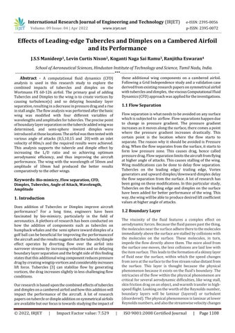
Fig 1 (e): WingwithTuberclesandDimplesISSN:2395 0056
ISSN:2395 0072
ThismodelcalculationhastobecarriedoutforLiftand CoefficientofLiftaswellasforDragandcoefficientofdrag.
AngleofIncident(α) =10degree
Lift(L) = 251.07N
Drag(D) = 36.698N
VelocityV=80m/s
Densityρ=1.225kg/m
SurfaceArea(s)= 0.052945m2
Lift (L)=251.07N
Drag (D)=36.698N
CoefficientofLift(CL)=2L
Fig-2(b):


Present study is conducted at chord based Reynolds NumberRe=120000,thecorrespondingupstreamvelocity at the chord length of 100mm is 80m/s at sea level conditions. As at this value of free stream velocity. Therefore the continuity equation and momentum equationfortheincompressibleflowaregivenasfollow.

CoefficientofLift(CD)=2D/

=1.22
=0.17832
Fig-2(a): MeshedFig-3(i)


Fig-3(j)
 Fig 3(c): StreamlineFlowOverWing(DimpleWing)
Fig 3(d): CLvsAngleofAttack
Fig 3(e)
Fig-3(g):PressureContourof TubercleWing
Fig 3(h):PressureContourofTubercle+DimpleWing
CoefficientGraphofPlaneWingat
Contour
CoefficientGraphofPlaneWingat
Fig 3(c): StreamlineFlowOverWing(DimpleWing)
Fig 3(d): CLvsAngleofAttack
Fig 3(e)
Fig-3(g):PressureContourof TubercleWing
Fig 3(h):PressureContourofTubercle+DimpleWing
CoefficientGraphofPlaneWingat
Contour
CoefficientGraphofPlaneWingat
Research Journal of Engineering and Technology (IRJET)
Volume: 09 Issue: 04 | Apr 2022 www.irjet.net
Fig 3(k):PressureCoefficientGraphofW50A10wingat0AOA

Fig-3(l):PressureCoefficientGraphofW50A10wingat20AOA
Fig 3(m):PressureCoefficientGraphofW50A10wing with TuberclesandDimples(together) at0AOA


Fig-3(n):PressureCoefficientGraphofW50A10wing with TuberclesandDimples(together)at20AOA
e ISSN:2395 0056
p ISSN:2395 0072
All of the above mentioned configurations have been subjectedtoanalysis.Thefindingsforthevarioussettings have been provided in tables and has been represented graphically.
Wediscoveredthattheconfigurationoftheaircraft wing with tubercles that have wavelength (50mm) and amplitude (10 mm) has offered the best performance in terms of maximum Angle of attack and coefficient of Lift withaconsiderableamountofDrag,andthenthistubercle addedwingwasfurthermodifiedbyaddingdimplesatthe pointwheretheboundarylayerbegantoseparate.
OnAnalysiswefoundthattheaircraftwingswithtubercles and dimples (together), are more efficient than the aircraft's plain wing. The wing's performance has also increased, witharemarkableimprovementintheliftforce.
1) Inthefuture,theanalysiscanbereplicatedbyaltering the wavelength and amplitude as well as the forms (shapes,geometry,patterns)ofthetubercles.
2) Structuralanalysisofthemodelcanbedoneinthenear future
3) TheGeometryofthemodelcanbemodifiedbyadding strutstothewing andanalysiscanbeperformed.
1) D.S.Miklosovic,M M Murray,L E Howle,andF E Fish, "Leading edge Tubercles Delay Stall on Humpback Whale (Megaptera novaeangliae) Flippers",PhysicsofFluids,Vol.16,No.5,May2004.
2) F E Fish,P.W Weber,M M Murray, andL Howle,
"The Tubercles on Humpback Whales’ Flippers: ApplicationofBio InspiredTechnology", Integrative andComparativeBiology,Vol 51,No 1,pp 203 213, May15,2011.
3)
J.Andreas,K.Theobald,B.Kerschgens,”CFDsimulations oftheflowaroundahumpbackwhale'spectoralfin”, 17th biennial conference on the biology of marine mammals Capetown, South Africa 29th Nov. 3rd Dec
4) AhmedFaroukAbdelGawadTransactionOncontrol andmechanicalsystems,“UtilizationofWhale Inspired TuberclesasaControlTechniquetoImproveAirfoil Performance”,Vol 2,No.5,PP.212 218,May,2013.
9001:2008
International Research Journal of Engineering and Technology (IRJET)
Volume: 09 Issue: 04 | Apr 2022 www.irjet.net
5) Vishal Kaushik, Manoj Mahore, Sandeep Patil, “Analysis of Dimpled Wing of an Aircraft” , IJEDR 2018|Vol6,Issue3.
6) K.L.Hansen,R.M.KelsoandB.B.Dally,“AnInvestigation ofThreeDimensional Effectsonthe Performanceof Tubercles at Low Reynolds Number”, 17th Australasian Fluid Mechanics Conference Auckland, NewZealand5 9December2010
7) Yin Yin Htay Aunga*, Myat Myat Soeb, Aung Myat Thuc. “Effect of Attack angle on Aerodynamics Analysis of Different Wind Turbine Wings using NumericalSimulation,”AmericanScientificResearch Journal for Engineering, Technology, and Sciences (ASRJETS).
8) Hardeepsinghlaal,Jaithrakhanna,harshkhatri, Sahilmhapankar,parmeswarpaul,AnjaliAvyaas.“ Effectoftuberclesonaerodynamicperformanceof NACA0015,”IRJETvolume6issue3,2019.
9) A.GrossandH.F.Fasel.“NumericalInvestigationof Different Wind Turbine Airfoils,” AIAA Aerospace SciencesMeetingincludingtheNewHorizonsForum andAerospaceExposition,Oriando,Florida,2011.
10) D. Hartwanger and A. Horvat. “ 3D Modelling of a WindTurbineUsingCFD,”EngineeringSimulation: EffectiveUseandBestPractice,Cheltenham,United Kingdom,2008
2022,
e ISSN:2395 0056
p ISSN:2395 0072
Impact Factor value: 7.529 | ISO 9001:2008 Certified
1114