
Energy Management System in Microgrid with ANFIS Control Scheme using Heuristic Algorithm.

1PG Student, Department of Electrical Engineering, Government College of Engineering Aurangabad, Maharashtra.
2Associate Professor, Department of Electrical Engineering, Government College of Engineering Aurangabad, Maharashtra
***
Abstract Renewable energy sources (RES) are inherently variable resources. Especially in solar and wind turbines, wherein an abrupt range of solar and wind speeds causes power variations. This disrupts the power system's stability and greater operation with electricity. Energy storage devices such as battery storage systems (BSS) are being introduced to the grid to overcome these issues. The battery system is also utilized to reduce power fluctuations and to effectively balance the produced as well as demand energy. BSS is also used to assist balance load requirements by providing additional power. The proposed EMS interfaces with the ANFIS controller to govern the performance of both the battery as well as solar and wind systems based on demand. Mostly The battery management system (BMS) is an example of this, adaptive controllers assist in monitoring the battery's State of charge limitations to ensure that the necessary charging and discharging times are achieved. A brief overview of EMS procedures is presented in this study., which are simulated in MATLAB/Simulink, which is being used to validate the suggested controller. The simulation results demonstrate the suggested controller functions as an EMS and BMS, as well as being employed for power balancing between production and load, with efficiently mitigating power fluctuations during varyingloads.
Key Words: Energy Management System (EMS), Energy Storage System (ESS), Adaptive neuro fuzzy inference system(ANFIS),Microgrid(MG),andStateofCharge(SOC).
1. INTRODUCTION
Nowadays one of the most challenging tasks is integrating renewable energy sources into the utility system because electricityisunreliableandalwaysfluctuates[1].Thegrid's sustainabilityisaffectedbythenetenergyflowthere;thus, the balance must be maintained. As more RES are incorporated into the system, power fluctuations become even more of a problem. Several studies have worked on thisproblem,andafewofthesolutionsproposedtoresult in additional usage of battery banks or other forms of energystoragei.e.,ESS.[2] RESisconsideredastheprime alternative to conventional energy resources, as its vast accessibility throughout maximal energy demand and effectual amount of power supplied for robust grid support.However,thepowergeneratedfromthesolarand wind is unsteadily caused by climatic disparity; hence, solarandwindpowerareinadequatetomaintainthegrid.
TheRES’scapacitytofulfilldemandandmaintainflexibility isSignificant.Therefore,ESSusedinconjunctionwithwind and solar power to provide output power stability is presented [3]. For optimal insertion of RES, MGs are configured in the system. These systems are characterized as power management approaches that integrate DERs with groups of loads by regulating MG power flow. MGs mayoperateineithergrid connectedorgrid isolatedmode [4]. Large scale renewable DERs are becoming incredibly popular in conventional power systems. They have been mostlyoff grid interconnection previously.Furthermore,a substantial number of renewable DERs are now being integrated into low/medium voltage distribution systems, creating serious hurdles to the system's operation and protection[5].TheEMSplaysacriticalroleintheefficient use of renewable energy sources to meet load requirements. EMS is a combination of computer assisted toolsused
1.Premisei.e.,baseorreference
2.Consequence i.e., result by power systems managers to evaluate, regulate, and optimize the productivity of generationresources[6].DuetotheinstallationofRESs, EMS currently plays a crucial part in MGs. The power flow of MG is regulated by a succession of converters. The energy management algorithm that governs the envisaged grid controls how well these converters react to grid fluctuations [7]. Traditional controllers, such as PIDcontrollers,havebeenusedinthepowerindustryfor decades to constrain point of common coupling (PCC) voltage, and they are very responsive to dynamical systems, which could also result in an unsteady, oscillatory, or stagnant response while working circumstanceschange[8].
This research presents an energy management approach thatreliesonANFIS,composedofRES, ESS,andanANFIS based control scheme, which is a much more advanced AI technology while contrasted to the fuzzy system. The core contributionofthisworkistheimplementationofANFISas a supervisory control system for grid interconnected RES for the estimation of energy that should be supplied by/stored in the ESS. ANN, FIS, as well as neuro fuzzy systemsareadvancedcontrolstrategiesthatdonotrequire apreciseprototypesystemtoworkandareundisturbedby system dynamics. Therefore, intelligent controllers can execute under a variety of circumstances [9]. Traditional
*Pooja Shivaji Kale1, Dr. N. R. Bhasme2
rule based techniques require a detailed mathematical description of the system and are extremely sensitive to parameter changes. [10]. There are more effective and adaptable ANN, FL neurofuzzy than conventional ones because they don't necessitate an accurate scheme's representation as well as improve the system's dynamic behavior. While compared with another neuro fuzzy scheme, the ANFIS has a quicker computational efficiency. ANFISisasmartplatformthatincorporatesANN'slearning and concurrent processing capabilities with the fuzzy inferenceprogram'sinferencecharacteristics. TheANFISis the combination of hybrid soft computing techniques, Using superior level reasoning skills and inferior level computationalcommand,inadditiontotheneuralnetwork and fuzzy. ANFIS is a sophisticated adaptive network that may be used to describe complicated and nonlinear systemswithfewerinputandoutputtargetparameters.In the structure of ANFIS, there are two different parameter groups:
TrainingANFISmeansadeterminationoftheseparameters using an optimization algorithm. The selection of optimizationmethodsutilizedintrainingisveryimportant togeteffectiveresultswithANFIS.
There are the following types of algorithms used in ANFIS training.
1.Derivatebased(GD,LSE,etc.)and
2.non derivative based (heuristic algorithms suchas GA,PSO,ABC,etc.).

It has been observed that heuristic based ANFIS training algorithmsarebest.
2. PROPOSED SCHEME
The proposed EMS is simple and operates using an intelligent logic for the switching algorithm. According to variablesolarandwindspeedsandloadcircumstances,the proposed algorithm generates dynamic standards for each subsystem. In addition, utilizes all renewable energy sources and battery storage technologies effectively. The suggestedsystemoffersa rathermoreoptimalpowerflow with higher power quality and dependability. It comprises thefollowingContents:
Table 1: NominalPowerofDGUnitsandLoad
RatedPower(kW)
Load(kW)
PV 500 L1 L2
WIND 500 200 350
BESS 400
e ISSN:2395 0056
ISSN:2395 0072
2.1. Wind generator WINDGENERATOR
TheWTisillustratedbyaschemethatincludestheturbine and generating system components. As stated by the actuator disk theory, the turbine model represents the mechanical power collected by the wind concerning wind speed as well as blade TSR. Moreover, WT generating system includes a damping resistor at dc bus that dissipates power surplus with relatively high winds maintaining WT rated power. Power surplus with relatively high winds maintaining WT rated power. The wind turbine I used to convert mechanical energy from wind energy. Eq. 1 expresses the mechanical power of a windturbine.
Where,
Pm Mech.outputpower
Ρ Densityofair.
A Bladearea.
Vω Speedofwind.
Β pitchangledegree.
Cp(λ,β) powercoefficient.


ThepowercoefficientiscalculatedbyEq.(1).

With
Where, non linearfunctionofboththe
TipSpeedRatio(TSR) Thepitchangles.
9001:2008
www.irjet.net
ISSN:2395
ISSN:
Outputcurrent. Photocurrentduetoirradiance.
Diodesaturation current.V Cellvoltage.q Charge.n Unidealconstantof thediode.k Boltzmann’s
shuntresistance.
Fig 2.MATLAB/Simulinkmodelofawindturbine.
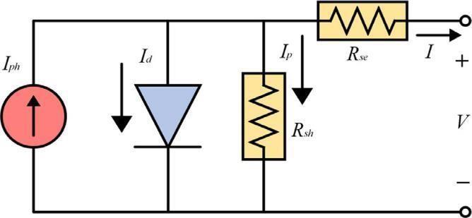
2.2. Solar PV
The Photovoltaic system uses a single diode model to represent each PV panel, whichis made up of optimal PV cells. This system offers high precision and the variables areeasilyobtainableinindustrialdatasheets[11],making itideal forPV devicecomputationsusing converters. PV outputvoltagethatisconvertedtodc bus voltageusing a dc dc converter governed with the MPPT technique. The equivalentcircuitdiagramisshowninFig2. …….4 Where,


Celltemperature. Seriesresistance.


Fig 3. EquivalentDia.ForPVCell
 Fig1. Blockdia.oftheproposedmodel
TheequationrepresentingtheoutputcurrentofaPVcellis asfollows:


Fig 4. MATLAB/Simulinksolarmodel
2.3. Energy storage system (ESS)
Badweathercausesconsiderable variationinsolar aswell aswindspeed,resultingininstabilityinthesolarandwind energy production process that offers power reduction to thepowergridowingtoinadequatepowersupplyfromthe energy production. In this instance, sustaining the DC connection voltage includes the deployment of an energy storage technology including batteries to counteract grid disruptions. For any overabundance of solar and wind energy,thebatterywouldrecharge. Wheneverwindspeed falls owing to inclement weather, wind energy decreases, causingthebatterytodeplete.InESS,alead acidbatteryis used for the hybrid system. This battery technology is typicallytheinexpensivereservebatteryforanyoperation, whileyetgivingadequateperformanceanddurability[13].

3. ENERGY MANAGEMENT STRATEGY
After the ANFIS has been trained, the following steps should be taken. For the proper sending of troops, a plan has been used. Battery energy to smooth out the system's output power the total power generated is one of the two inputstotheANFIS.Atthecurrentmomentbythesystem, the other is the command smoothing power output's previousvalue.TheANFISprovidesaresultfromthesetwo inputs, the battery's power is controlled and the entire power is then deducted from this power available at batteries. Depending on the sign of the power, this power dictates whether the battery must charge or discharge. The battery must discharge if the indication is positive; else, yielding charged battery. This power is also susceptible to maximal and minimal restrictions, which contributetoeitheralackofsmoothingpowerorasurplus ofpowerthatwillbedischarged.Ithastwomodes:
Fig 5. EquivalentDia.ForBatteryEnergyStorageSystem (BESS)
i. Excess power mode (EPM) ii. Deficitpowermode((DPM)
The two modes of operation are determined by the availability of renewable power generation and the system's load demand. Based on the state of SOCb and SOCsc, four different operating circumstances are discoveredintheDPMandEPMmodes,asindicatedin
Where battery’sinstantaneouscapacityAh. Q Battery’smaximalcapacityinAh.
ThefollowingexpressthevariationofthebatterySoC: ………5
It is vital to control the battery's SoC to prevent overcharging or undercharging to extend the battery's life.Theassociatedconstraintcanbewrittenasfollows:
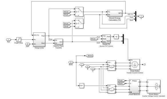
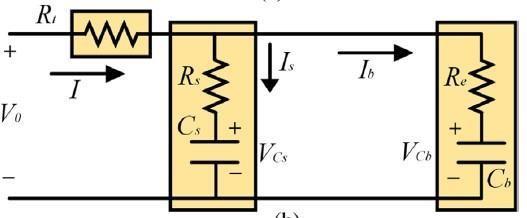
Table2.ThesuggestedEMSachievesthefollowinggoals:
1. Maintain the SOCb and SOCsc within their safe operating ranges, which are the prescribed higher (H)andlower(L)SOClimitations.
2. Minimizebatterystressandextendbatteryenergy lifespan.
3. Lessintensiveintermsofcomputing.
Fig 6. MATLAB/SimulinkModelofEnergyStorageSystemTable 2: ModesofSystemOperatingConditions
Modes circumstances of operation
Mode1 Becausetheloaddemandislowerthanthe electricity generated by RESs, a power limitationisimposed.
Mode2 The power gap between RESs and load demand is smaller than the battery capacity. As a result, the storage system mustmeettheloaddemand.
Mode3 Because the combined output of the RES and the batteries is less than the load requirement, the CESs participate in energy management to achieve power balanceatthelowestpossiblecost.
Mode4 Because the load demand exceeds each RES and CES supply limit, the load switches to a restricted mode, in which all powersourcesareusedtomeetthecritical load's power requirement. This ensures systemstability.
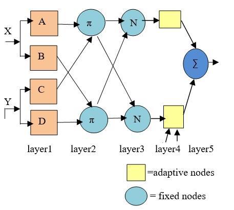
4. ANFIS CONTROL
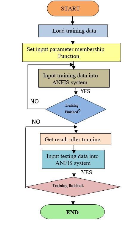
ANFISisa composite model thatcombinesANN plus fuzzy schemes to reap the benefits of these approaches. It integratesusingTakagi Surgeonadoptedthefuzzyscheme, with ANN optimizing the final fuzzy inference system. A typicalANFISsystemisseeninFig.8,Anadaptablenodeis representedbyasquare,whileafixednodeisrepresented bya circle.Amulti layerfeedforwardnetwork isdepicted inthisdiagram.Whileprocessingtheinputstoproducethe outputs,eachlayerhasitsfunction.Acollectionofinputas well as output element functions is connected with fuzzy ifthen rules to regulate the inputs and outputs. Unlike a traditional fuzzy scheme, I/O functions, as well as The ANFIS offers it an edge by employing ANN training to modify the rules and membership functions. Fuzzy if then rulesarereliantonhumanskill.Theprocessofcreatingan ANFIS system begins with the user intuitively selecting initial input and association functions according to the system's knowledge. If prior information is not accessible, the user can still pick associated functions. In addition, ANN executing procedure will then create a set of if then rules that are appropriate for data. Different learning algorithmsare used to optimize the fuzzy rules in place to evade entrapment into local minima and to increase efficiency. The hybrid technique incorporates the least squaresandtrainingalgorithmmethods[15].
Fig. 8. Configurationdia.ofANFIS


Eqs.(7)and(8)describeacommonrulesetfortheTakagi Sugenointerferencesystemwithtwofuzzylayers(8),


RULE1:
If is and is then,
RULE2: …………...8
If is and is then,
Fig 7. FlowchartofANFIScontrolscheme.Volume: 09 Issue: 04 | Apr 2022 www.irjet.net
Where, ArethelinearParametersAre thenon linearparameters.
Figure 8 depicts the ANFIS layer framework in a beautiful way.
1.Fuzzification layer.
ThefuzzylayeroutputisfurnishedinEq.(9) And Eq. (10) 9 10
(IRJET)
e ISSN:2395 0056
p ISSN:2395 0072
……………16
Where, de fuzzylayeroutputs.
5. Total output layer


It is possible to calculate the sum of the input signals, which is provided as .Eq. (17) provides the overalloutputofthelayer.


..........17
Where, thetotaloutput.
WhentheANFIStrainingiscomplete,thereferencepower toregulatetheHRES'energywillbeavailable.
Where, the fuzzy layer
Membership function ofthefuzzy.
2. Product layer
ThislayeroutputcanbedescribedbyEq.(11)andEq.(12) , ……….11 = , ………12


Where, And Theproductlayeroutputs.
3. Normalization layer
The corresponding layer is expressed in Eq. (13) and Eq. (14). ……….13 ....……14

Where, Thenormalizedlayeroutputsof.
4. Defuzzification layer


The defuzzification layer output is furnished employing Eq. (15)andEq.(16)


Power source
PV Wind
And and and output of And , ,
Table 3: Referencecalculation
Power control
Battery 4.1. ANFIS PID-Control for PV inverter The grid interfacing PV inverter includes four ANFISPID based control methods to manage active plus reactive power suitably to normalize voltage under customary circumstances and supply LVRT throughout the three phase’s Symmetry grid failure state. Each ANFIS control scheme is made up of three intelligent ANFIS controllers that are in charge of different control parameters. Four ANFIS PID based control methods have been assigned, twelve intelligent ANFIS controllers. The ANFIS PID based control system has been designed and studied to regulate gridinterfacingPVinvertersisshowninFig.9.Thetraining data set produced from simulations has been used to structure each of the twelve intelligent ANFIS regulators. For appropriately tuning for fuzzy parameters of ANFIS, a =
………......15
© 2022, IRJET | Impact Factor value: 7.529 | ISO 9001:2008 Certified Journal | Page651
collection of data has been compiled for each from simulations that completely depict the weak distribution system's dynamic behavior when combined with large scalePVs[16].
Fig. 9.ConfigurationofANFIS
4.2. ANFIS Supervisory EMS for ESS
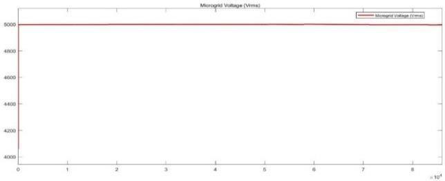
PV power generation progressively climbs, peaks around midday, and then begins to decline. The quantity of availableenergyleftoverlaterthanfulfillingtheconsumers is determined by the nonlinear performance of dynamic loading that varies throughout the day as well as year. By collaborating with the PV inverter control scheme, an ANFISsupervisoryEMSsmartlymanagestobalancepower generationandabruptloaddemand,theESSischargedand discharged, improving the system's voltage profile A Continuous charging/discharging rate strategy, which may resultinunderutilizedstoragecapacity,ispreferredtothis control technique. The SOC should be kept within the proper allowed range to avoid the battery bank from overcharging/over discharging [17]. The supervisory EMS basedonANFISprotectstheESSfrom beingcharged more than SOCmax and has been programmed to mimic the planned the supervisory EMS based on ANFIS protects the ESSFrombeingcharged more thanSOCmaxanddischarge dlessthanSOCmin.
Fig. 10. ConfigurationofANFISsupervisoryEMSforESS
Supervisory ANFIS has been programmed to mimic the planned supervisory management system using a collectionofdata.
5. SIMULATION RESULT AND DISCUSSION
The experimental results of the suggested algorithm implemented in a system with an Intel(R) Core (TM) i5
(IRJET)
e ISSN:2395 0056
ISSN:2395 0072
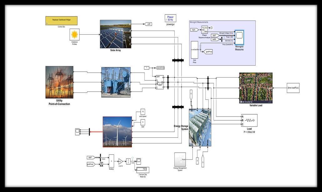
CPU, 4GB RAM, and the MATLAB/Simulink (R2021a) platform are described in this part. The proposed energy managementsystemisconstructedfortheHRESsystemin Figure 1 and its effectiveness is evaluated. Table 1 shows the planned model for the HRES arrangement. Depending ontheloadvariation, thesuggestedtechnique predictsthe reference power of the sources. The proposed approach requires the previous instant generated power from the energy sources, as well as the present time load demand, for this purpose. Depending on the load variation, the suggested technique predicts the reference power of the sources. The proposed approach requires the previous instant generated power from the energy sources, as well as the present time load demand, for this purpose. When the generated power is greater than the load requirement, the excess power is used to charge the storage devices. However, if the generated power is less than the load requirement, the necessary power is drawn from the storagedevices.
Table 4:SimulationparametersofHPS
Parameters
Values
PVratedpower 3.78kW
OpencircuitvoltageofPV 64.2V


ShortcircuitcurrentofPV 5.96A
Ratedpower ofWT 1kW
Batterynominalvoltage 26.4V
Batteryratedcapacity 6.6Ah
The efficiency of the suggested method is demonstrated using two different test cases: input power generation variation and output load variation. The suggested method is initially validated by varying the input power generation,buttheloadvalueremainsconstantat3.5kW nonlinearload(dioderectifierwithRload). Fig.13depicts the required reference load demand. The irradiation of the PV system is depicted in Fig.14 for the first test case. The output power generated by the PV is depicted in Fig.15 based on the irradiation level. The PV generator's output power ranges from 1.6 to 3.6 kilowatts. The PV's highest power is harvested between 0.25 and 0.85 seconds and 2 to 3 seconds. The minimum power generation occurs between 1.25 and 1.5 seconds. Currently,therequiredloaddemandismet byemploying PV and WT output. power, and storage devices output power.ThestandardP&Otechniqueisusedtoachievethe MPPTofthePVgenerationsystem.
9001:2008
PID Controller Fuzzy inference system PlantVolume: 09 Issue: 04 | Apr 2022 www.irjet.net
Fig.16depictsthegeneratedpowerfromtheWT.The standardP&OMPPTtechniqueisusedtoachievethe MPPToftheWT.
Technology (IRJET)
e ISSN:2395 0056
ISSN:2395 0072
Fig.15. OutputpowerofWT
Fig. 16. Batteryoutputpower
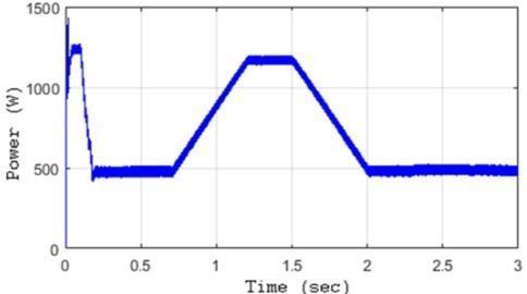

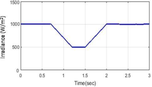
Fig.11. BlockIllustrationofProposedDesign load
Factor value:
Fig. 17. Totalpowergenerationwithreferencetothe
| ISO 9001:2008
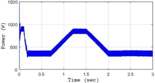 Fig.12.Loaddemandofthefirsttestcase
Fig.13.IrradiationofPVgenerator
Fig.14. OutputpowergeneratorbyPV
Fig.12.Loaddemandofthefirsttestcase
Fig.13.IrradiationofPVgenerator
Fig.14. OutputpowergeneratorbyPV
Fig. 18. Secondtestcaseloaddemand
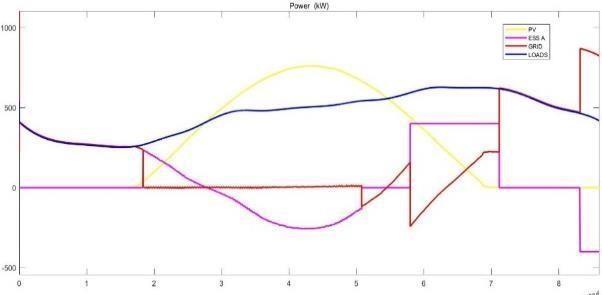
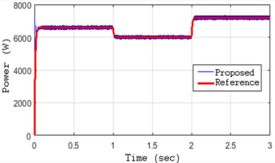
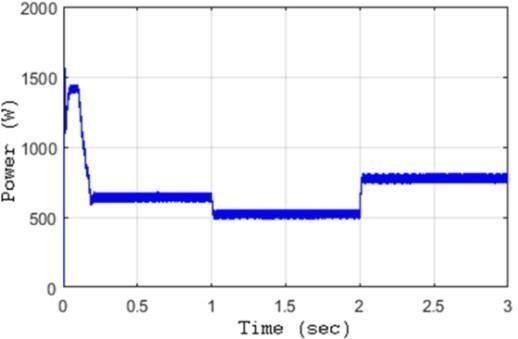
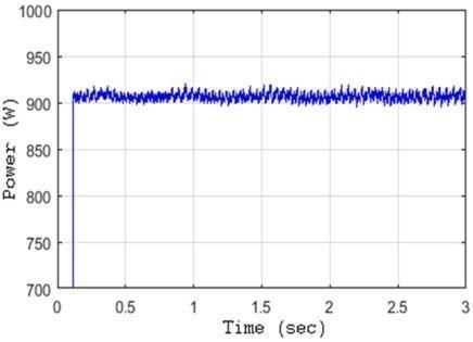
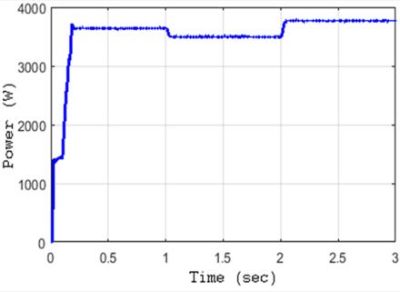
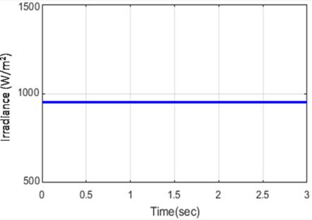
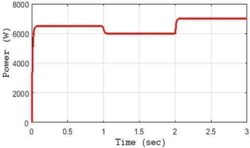
The second test case was carried out with the following loads:Ia5 kWresistiveloadconnectedviaadioderectifier from0to3sii)a500WactivepowerRLloadisconnected during 0 to 1 s, and iii) a 0.5 kW active power RL load is connected during 2 to 3 s, as illustrated in Fig.19. The constantirradianceandwindpoweraretakenintoaccount inthisscenario.Fig.20and21showtheirradiationandPV powerinthesecondtestinstance,respectively.During0.25 to 1 s, the PV's maximum power is extracted. Because the load value is reduced from 6.5 kW to 6 kW, the full power extraction is not required during the time period 1 to 2 s. The PV output is kept at 3.5 kW at this point, and the maximum power of the PV is extracted for another 2 to 3 seconds (3.78 kW). Figure 22 depicts the WECS's power output. The WECS output power is kept between 900 and 910watts.Figure23depictsthebatteryoutputpowerwith the proposed energy management. The amount of battery output power used is determined by the load variation. Fig.19 depicts the overall power generation when the energymanagementstrategyiscombinedloaddemand.
CONCLUSION
Thefocusofthisworkisonanenergymanagementsystem (EMS) utilized in a grid connected microgrid with a PV system,awindfarm,abatterystoragesystem,andvariable loads. An ANFIS technique has been developed to determine the ideal configuration of energy sources while taking renewable resource projections into account in order to minimize operating costs and grid dependence and optimize the usage of renewable energy and power exchange with the grid. This research has made an ANFIS based EMS of a grid connected hybrid system accessible and tested for a smart grid made up of renewable energy sources(WTandPVpanels).Italsosuggestsandevaluates the performance of an intelligent ANFIS based voltage control scheme for grid tied renewable energy systems at the PCC, Furthermore, it removes the need for costly conventional trial error methods for tweaking traditional PID attributes on regular basis by providing a "plug and play" function for automated tuning once installed. ANFIS is utilized to control electricity between the grids, and the
Fig. 19. IrradiationofPVgenerator
Fig. 20. OutputpowerofPV
Fig. 21. OutputpowerofWT
Fig. 22. Outputpowerofbattery
Fig. 23. Total power generation with load power reference
Volume: 09 Issue: 04 | Apr 2022 www.irjet.net
source, along with batteries. The outcome revealed that ANFIS provides higher performance with minimized fluctuations significantly. The proposed EMS is capable of fulfilling varying power requirements even while enabling energy management algorithms and efficient ESS deployment.
REFERENCES
[1] A. Mahesh and K. Sandhu, “Hybrid wind/photovoltaic energy system developments: Critical review and findings,” Ren. and Sust. Ener. Reviews, vol. 52, pp. 1135 1147,2015.
[2] E. Reihani, S. Sepasi, L. Roose, and M. Matsuura, "Energy management at the distribution grid using a battery energy storage system (BESS)," Int. J of Elect Pow&EnerSyst,vol.77,pp.337 344,2016.
[3] D. P. Jenkins, J. Fletcher, and D. Kane, "Lifetime prediction and sizing of lead acid batteries for micro generation storage applications," IET Renewable Power Generation, vol. 2, no. 3, pp. 191 200, Sept. 2008.
[4] N. Hatziargyriou, H. Asano, R. Iravani, and C. Marnay, "Microgrids," IEEEPowerandEnergyMagazine,vol.5, pp.78 94,2007
[5] Masters, C. L. "Voltage rise: the big issue when connecting embedded generation to long 11 kV overhead lines." Power Engineering Journal 16.1 (2002):5 12.
[6] E. Handschin and A. Petroianu, Energy management systems: operation and control of electric energy transmission systems: Springer Science & Business Media, 2012 [7] Li, Huijuan, et al. "Adaptive voltage control with distributed energy resources: Algorithm, theoretical analysis, simulation, and field test verification." IEEE Transactions on Power Systems 25.3(2010):1638 1647.
[7] Jang,Jyh ShingRoger."ANFIS:adaptive network based fuzzy inference system." Systems, Man and Cybernetics, IEEE Transactions on 23.3 (1993): 665 685.
[8] M. A. Akcayol, “Application of adaptive neuro fuzzy controller for SRM,” Adv. Eng. Softw., vol. 35, no. 3 4, pp.129 137,Mar.2004.
[9] M. G. Villalva, J. R. Gazoli, and E. R. Filho, “Comprehensive approach to modeling and simulation of photovoltaic arrays,” IEEE Trans. Ind.Electron., vol. 24,no.5,pp.1198 1208,May2009.
(IRJET)
e ISSN:2395 0056
ISSN:2395 0072
[10] M. A. S. Masoum, H. Dehbonei, and E. F. Fuchs, "Theoreticalandexperimentalanalysesofphotovoltaic systems with voltage and current based maximum power pointtracking,"IEEETrans.EnergyConver.,vol. 17,no.4,pp.514 522,Dec.2002.
[11] O. Tremblay and L. A. Dessaint, “Experimental validation of a battery dynamic model,” World Electr. Veh.J.,vol.3,no.1,pp.1 10,2009.
[12] N.Mahmud,A.Zahedi,andA.Mahmud,"ACooperative Operation of Novel PV Inverter Control Scheme and Storage Energy Management System Based on ANFIS forVoltageRegulationofGrid TiedPVSystem,"inIEEE Transactions on Industrial Informatics, vol. 13, no. 5, pp. 2657 2668, Oct. 2017, DOI: 10.1109/TII.2017.2651111.
[13] Yoshimoto, K., Nanahara, T., & Koshimizu, G. "New control method for regulating state of charge of a battery in hybrid wind power/battery energy storage system." Power Systems Conference and Exposition,2006.PSCE'06.2006IEEEPES.IEEE,2006.
Author Profile
Pooja Shivaji Kale
2022,
Aurangabad College of Engineering, Aurangabad affiliated to Dr. Babasaheb Ambedkar Marathwada university Aurangabad, India in 2017, from Electrical Engineering Department. She is currently

ShehadreceivedherBachelor’sDegreefrom workingtowardsherMaster’sDegreefromGovernment College of Engineering Aurangabad, India, in Electrical Power System specialization from the department of Electrical Engineering, 2021. Her interested research areas are Renewable energy technologies, Microgrids. She has published review paper, A Review on Energy managementtechniquesinAC/DCMicrogrids.
Dr. Nitin Bhasme

HeisworkingasanAssociateProfessor in Electrical Engineering at Government College of Engineering, Aurangabad since 1998.Hehascompletedundergraduationin Electrical Engineeringin1993fromGovernment College of Engineering, Aurangabad. Thereafter completed postgraduation and Ph. D. from same institute. He has guidedmorethan30studentsatPGlevelandmorethan 150 students at UG level. Currently he is a Research Guide in Electrical Engineering and his areas of interest arePowerElectronics,ACandDCDrivesandRenewable EnergySystems.
Factor value: 7.529 | ISO 9001:2008