1M. Tech Scholar, Dept. of Electrical Engineering, GBPUAT, Uttarakhand, India 2Professor, Dept. of Electrical Engineering, GBPUAT, Uttarakhand, India ***
CONTROL STRATEGIES ON GRID TIED PV INVERTERS
Keywords: Photovoltaic (PV) system, Distributed Energy Resources (DER), Distributed Generation (DG), Maximum power point tracking (MPPT), Perturb & Observealgorithm(P&O),Phase lockedloop(PLL)
1. INTRODUCTION
Thedemandforrenewableenergyhasgrownasaresultof global warming and the finite supply of fossil fuels The integrationofDistributedEnergyResources(DER)systems based on renewable energy resources into the distribution grid has fascinated interest in recent years. Solar radiation isthemostabundantrenewableenergysource InIndia,the average annual solar energy incident on land is around 5000 trillion kilowatt hours, representing a massive solar energy production potential [1] The solar energy received inayearexceedsthecombined energyoutputofallIndia's fossilfuelreserves.Solarenergyhasrisentoprominencein recent years as a result of its widespread availability and environmentally friendly operation. Due to various subsidies and promotion proposals provided bygovernments around the world renewable energy sources getting more popular. Without any moving parts, photovoltaic (PV) power generators convert the energy of solarradiationdirectlytoelectricalenergy.Thishappensin materials that have the ability to absorb photons and emit electrons. Silicon is the most common material used in photovoltaics. Because of distinct advantages such as simplicity of allocation, high dependability, absence of fuel cost, low maintenance, and lack of noise and wear due to the absence of moving parts, photovoltaic generation is gaining increased importance among renewable energy source applications [8]. The utility uses a bidirectional meter to transfer excess energy to the grid during average or low peak demands, and the concept of net metering is used by theutility. Grid connected solarinverters can only produce active power where maximum power can be extracted with theuseofMPPT [6,7].Electrical loadstend to consume more inductive reactive power because they arepredominantlyinductiveloads.Currently,thegridisthe only source of reactive power. The site power factor becomespoorfromautilitystandpointasalargenumberof Distributed Generation (DGs) that inject only active power into the grid become more prevalent, affecting grid performance. Previously, for power quality issues, reactive power injection/absorption was done through FACTS devices. However, these devices have the disadvantages of large size, high cost, large installation area, and so on. It is necessary to regulate the reactive power flow in the network,asthismayhaveanimpactonvoltageregulation. Asthenumberofgrid connectedinvertersgrows,theiruse asVARcompensatorswillaidgridvoltageregulationwhile reducing the need for costly capacitor banks. Control strategies for grid connected solar inverters to supply reactivepowerinadditiontoactivepowerforvariousloads and varying irradiance are discussed in this paper. The specialcaseofinductiveorcapacitiveloadconnectionswill result in a significant change in bus voltage, which will exceed the system voltage specification, resulting in poor systemstability.Toensuregrid connectedvoltagestability, the distributed control strategy is proposed to control the reactive power output, and active power reduction is used as a backup strategy to control the voltages in the PV system [4, 9, 10]. The problems of large scale PV grid connection, as well as active power regulation, reactive power control, and low voltage crossing methods, are summarisedin[2,3,5,11]
©
International Research Journal of Engineering and Technology (IRJET) e ISSN: 2395 0056 Volume: 09 Issue: 03 | Mar 2022 www.irjet.net p ISSN: 2395 0072 2022, IRJET | Impact Factor value: 7.529 | ISO 9001:2008

Abstract - The grid voltage fluctuates easily due to load changes, affecting the grid's power quality. Grid tied solar inverters are capable of producing active power only. The reactive power demand of load is solely fulfilled by the grid only. Reactive power drawn from the grid has increased significantly in comparison to active power as a result of the significant rise in the implementation of renewable based Distributed Energy Resources. If the grid connected solar inverter is smart enough to supply reactive power in addition to active power, the grid's reactive power requirements will be reduced because the grid will have to supply less reactive power. In this paper for different environmental conditions such as irradiance and temperature and for different loads, the flow of active and reactive power from the solar inverter is studied. MATLAB/SIMULINK software is used to validate the results.
Certified Journal | Page522
Himani Pant1, Sudha Arora2
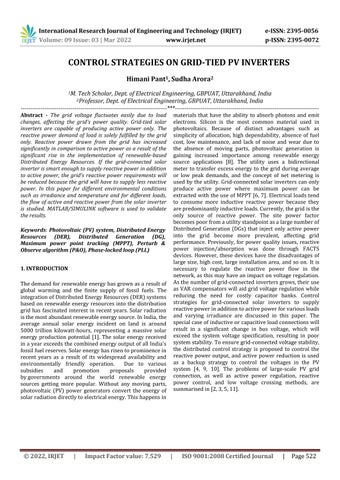
Where,Iphislightcurrent I0isdiodereversesaturationcurrent
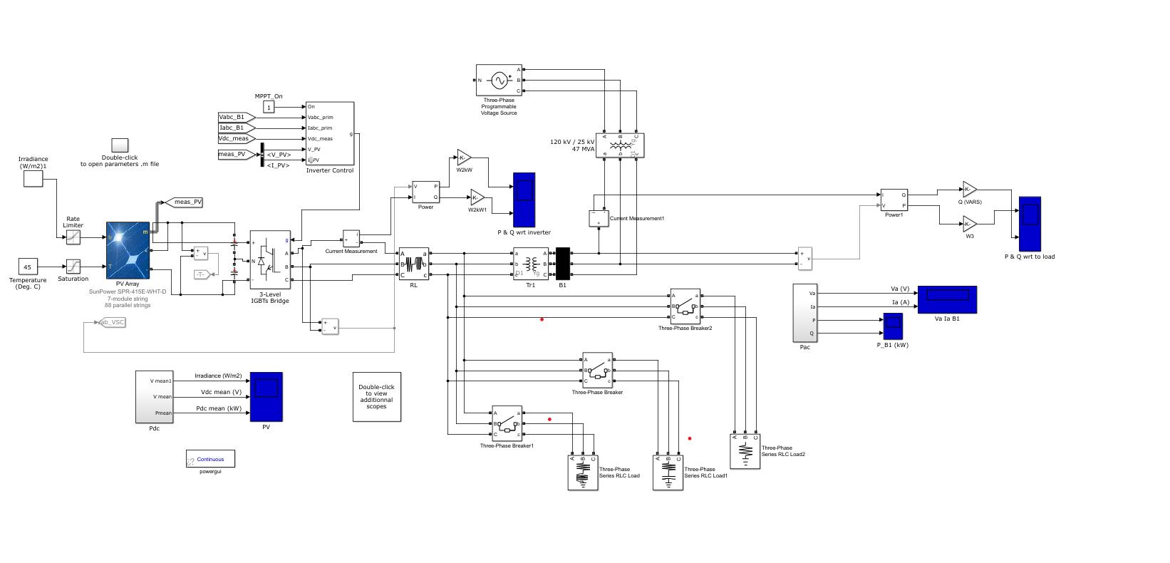
In this paper, we studieda grid connected photovoltaic generation system that includes a PV array, power electronicconverters,controllers,localloads,andtheutility grid (Fig 1). The paper presents an investigation into the system's detailed modelling. A voltage source inverter connects the PV array to the utility grid, converting the solarmodules'DCoutputvoltageintoanAC.Theinverter's DCinputmustbeconstant, whichiscontrolledbya dclink capacitor. In Matlab/Simulink Software, the proposed model of the entire components and control schemeis simulated. The validity of the models and the effectiveness of the control methods have been confirmed by all simulationresults. 2. PHOTOVOLTAIC SYSTEM
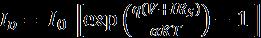
Fig. 2: EquivalentstructrureofPVcell (3)
A photovoltaic system is made up of many strings of solar cells connected in series and in parallel to provide the desired output voltage and current. Fig. 2 shows the equivalentcircuitofaPV,whichcanbeusedtocalculatethe nonlinear I V characteristic. As a result, the cells are connected in series and parallel to form an array with the desired voltage and power levels. The current through the parallel diode in the single diode equivalent model can be givenas: (1) ByusingKirchhoff’slawinequivalentcircuitofPVoutput currentcanbewrittenas: (2)
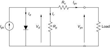
Fig. 1: ModelforgridtiedPVanditscontrolschemes
International Research Journal of Engineering and Technology (IRJET) e ISSN: 2395 0056 Volume: 09 Issue: 03 | Mar 2022 www.irjet.net p ISSN: 2395 0072 © 2022, IRJET | Impact Factor value: 7.529 | ISO 9001:2008 Certified Journal | Page523
Certified Journal | Page524
TisthecelltemperatureindegreesKelvin qistheelectroncharge
TABLE 1 ParametersofPVArray Panelused SunPower SPR 415E WHT D Noofcells 128 MaximumPower 414.801 OpencircuitVoltage 85.3 Shortcircuitcurrent 6.09 Solarintensity(W/m^2) 1000 Diodeidealityfactor 0.87223 Shuntresistance 419.7813 Seriesresistance 0.5371
Volume: 09 Issue: 03 | Mar 2022 www.irjet.net p ISSN: 2395 0072 © 2022, IRJET | Impact Factor value: 7.529 | ISO 9001:2008
International Research Journal of Engineering and Technology (IRJET) e ISSN: 2395 0056
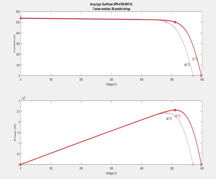
Fig. 3 shows the mathematical model of PV array that includesbothseriesandparallelmodules.ThedatainTable 1 is used to value all of the model's parameters. Fig. 4 shows the output characteristics of the PV array with temperaturesandsolarradiation.
4. PQ CONTROL METHOD
Ir iscurrentintheparallelbranch Rs istheseriesresistance Rpistheparallelresistance αisthediodeidealityfactor kistheBoltzmannconstant(1.3806503×10 23 J/K)


A common DC/AC inverter connects the PV array to the ac gridviaadc linkcapacitor.Tomaketheinductancecurrent track the sinusoidal reference current closely, the inverter is used in current control mode with a PWM switching mechanism. Internalandexternalcontrolarethetwo most importantaspectsofcontrol.
Fig 3: MathematicalmodelofPVarray where NS and NP are the series and parallel cell numbers, respectively.Whencellsareconnectedinseries,theoutput voltage is increased, and when they are connected in parallel,theoutputcurrentisincreased.TABLE1showsthe data used by PV array. Fig. 4 shows the output characteristics of a PV array at various temperatures and solarradiations.
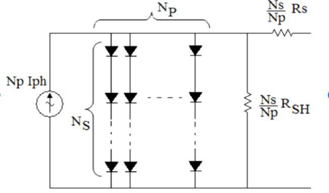
Fig 4:CharacteristicsofPVcell 3. MPPT ALGORITHM In order to determine the maximum power point, many MPPT techniques have recently been developed. Due to high accuracy at MPP, variable step size P&O are the most important used MPPT techniques. The principle behind variable step size P & O algorithms is that when the operating point is far away from the MPP, the algorithm increasesthesize of the increment, resulting in faster MPP tracking, whereas when the operating point is close to the MPP, the step size increment is too small, resulting in very small oscillations around the MPP, contributing to increased PVsystem efficiency. Step size usedin theMPPT algorithmisgivenbythefollowingequations: Step1= (4) Step2= (5) NWithis the scaling factor and A1, A2 are normalizing coefficients.
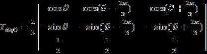
Thedc linkvoltageisregulatedbyanexternalcontrolloop. The DC link voltage of a grid connected inverter is stabilized with DC link capacitors. The injected voltage to thegridrisesasthedrawnenergyfromPVrises.Asaresult, theDClinkvoltagecanbekeptconstant. Id and Iq grid currents are regulated by an internal control loop (Components of active and reactive current) The dc voltage controller's output is the Id current reference. In addition,theproposedsystememploysdq0transformation equations, a PLL algorithm for grid synchronization, and active/reactive power calculation. Park transformation
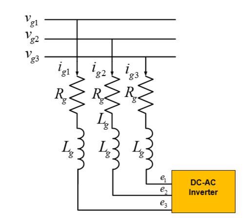
Where, (7) Consider an inverter connected to the network via a resistor R and inductance L (which represent a simplified model of a transformer) in order to grasp the general principleofcontrolmethodwhichasindicatedinFig 5
TheeffectofPQcontrolonthegrid connectedvoltagewhen aninductiveorcapacitiveloadisconnectedtothegridand for different irradiances is investigated in this paper. An inverter bridge module, a voltage and current detection module, a phase locked loop module, a coordinate transformation module, a control module, and an SPWM moduleareallincludedintheproposedcontrolstrategy. Test 1:Irradianceisconstantat1000W/m2
The basic circuit equation for the grid connection to the gridcanbewrittenasfollowsusingtransformationtheory:(8) where Vg and Ig represent the voltage and current of the grid,Rg andLg areresistanceandinductanceofthegridand eistheinvertervoltage.
SIMULATION RESULT
International Research Journal of Engineering and Technology (IRJET) e ISSN: 2395 0056
Volume: 09 Issue: 03 | Mar 2022 www.irjet.net p ISSN: 2395 0072 © 2022, IRJET | Impact Factor value: 7.529 | ISO 9001:2008 Certified Journal | Page525
Fig. 5: Grid connectedinvertercircuit
The dq reference frame theory is responsible of power control for grid connected inverters, which results in power determination in a reference frame. The active power control and reactive power exchange components, Idref and Iqref,arecontrolledtoachieveactivepowercontrol and reactive power exchange, respectively, and are commonly used to influence a desired power factor. The grid's active and reactive power can be expressed as follows: (10)(9) where vd and vq represent the direct and quadrature grid voltage components, respectively, and id, iq represent the inverter's direct and quadrature output current components.Thesecurrentsaredeterminedbytheamount of power requested and the voltages measured at the connection point. Before calculating the currents, this voltageistransformedinthedqframe. Theactivepoweris proportionaltoid andthereactivepowerisproportionalto iq A reference generator block is used after the values of direct and quadrature axis components are obtained from thePLLforgridcurrent.Thevaluesofreferencecurrentin both the direct and quadrature axis are generated in this reference generator system. The current reference calculator uses the following equations to generate the valuesofIdref andIqref: 5.
transformsthegrid voltages andcurrents fromabc toa dq frame,androtationalfrequencyωtisgeneratedwithPLL. = * (6)
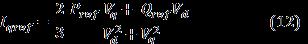
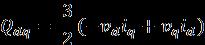

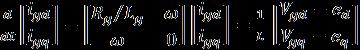


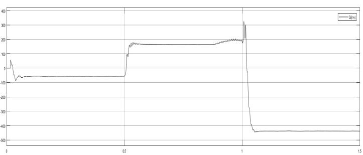
Fig 6: Activeandreactivepowerbytheinverter
International Research Journal of Engineering and Technology (IRJET) e ISSN: 2395 0056
|
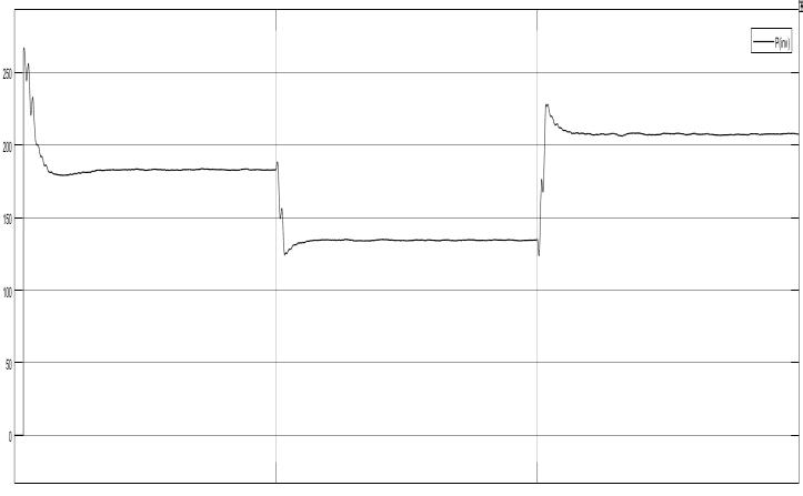
Fig. 7:Activeandreactivepowerfromthegrid
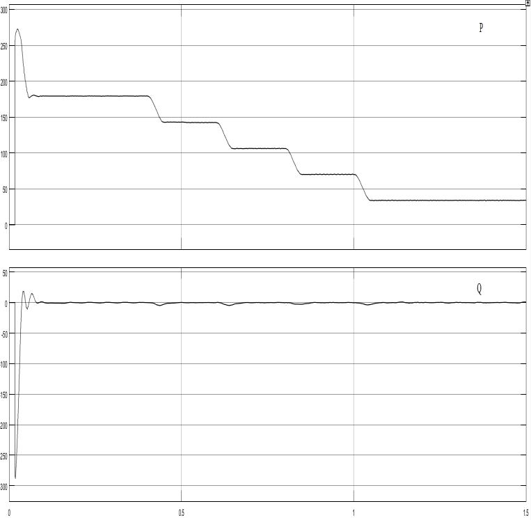
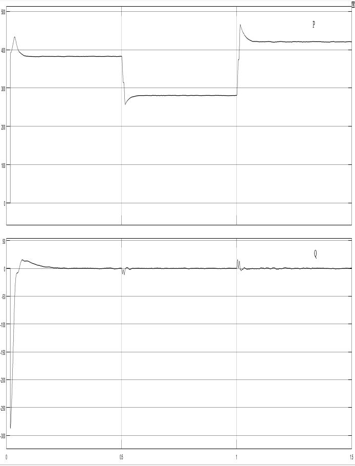
Fig. 9: Activeandreactivepowerfromtheinverter
Volume: 09 Issue: 03 | Mar 2022 www.irjet.net p ISSN: 2395 0072 © 2022, IRJET Impact Factor value: 7.529 | ISO 9001:2008
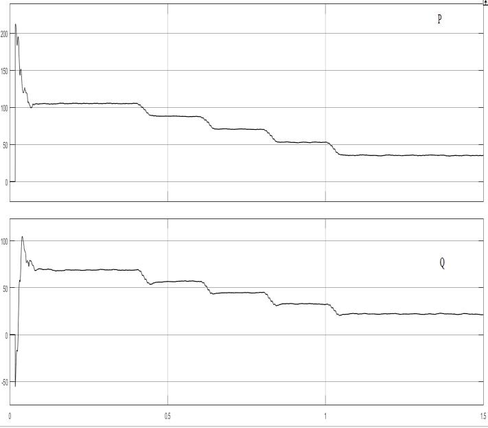
Fig. 10: Activeandreactivepowerofgrid

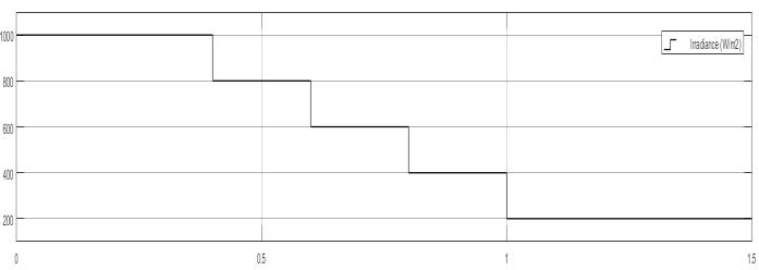
Fig 9 shows the behaviour of active and reactive power supplyfrominverterfordifferentvaluesofirradiances.The irradiance is adjusted in 200 unit steps from 1000 to 200 W/ .
Certified Journal | Page526
Fig. 7 shows the active and reactive power supplied from grid.Fromthepowersgraphofgrid,itisclearthat reactive powerfromgridisalwaysaroundzero.
Reactivepowertotheloadissuppliedfrom theinverteras shown in Fig. 6 In the proposed scheme inductive load is connected between 0.5 to 0.1 and capacitive load is connected between 0.5 to 1 with the help of breakers. It is clear from the graph that for inductive load inverter is supplying reactive power and for the capacitive load it is absorbingreactivepowermeansreactivepowerispositive fortheinterval0to0.5andnegativefortheinterval0.5to1. ActivepowerissuppliedaccordingtoMPPT.
Test 2: Irradiance is varying as 1000 W/ , 800 W/ , 600W/ ,400W/ and200W/ Fig. 8: Varyingirradiance
International Research Journal of Engineering and Technology (IRJET) e ISSN: 2395 0056 Volume: 09 Issue: 03 | Mar 2022 www.irjet.net p ISSN: 2395 0072 © 2022, IRJET | Impact Factor value: 7.529 | ISO 9001:2008 Certified Journal | Page527
[4] S. Palle, N. Arafat, Y. Sozer and I. Husain, "Voltage harmonic control of weak utility grid through distributed energy systems," IEEE Energy ConversionCongressandExposition,Raleigh,2012, pp.1982 1989.
REFERENCES
[8] Darabian, A. Jalilvand R.Noroozian M. "Modeling and control of multi level inverter for three phase grid connected photovoltaic sources." International Journal on Technical and Physical Problems of Engineering15(2013):35 43 [9] Al Shetwi,A.Q.,Hannan,M.A.,Jern,K.P.,Alkahtani,A. A.,&PGAbas,A.E.(2020).PowerQualityAssessment of Grid Connected PV System in Compliance with the Recent Integration Requirements. Electronics, 9(2), [10]366.Molina,MarceloGustavo,andEmmanuelJesúsEspejo. "Modeling and simulation of grid connected photovoltaic energy conversion systems." International journal of hydrogen energy 39.16 (2014):8702 8707.
[7] Mollah,A.Hossain,G.K.Panda,andP.K.Saha."Three phase grid connected photovoltaic system with maximum power point tracking." International Journal of Advanced Research in Electrical, Electronics and Instrumentation Engineering 4.5 (2015).
TABLE 2: ActiveandReactivePowerValues Timeinterval Active(kw)Power Reactive(kVAR)power 0.1 0.4sec 120 80 0.4 0.6sec 94 61 0.6 0.8sec 75 50 0.8 1sec 53 35 1 1.5sec 24 16 From the above table, it is clear that in this mode of operation power factor is fixed to 0.83. The results show that the grid connected inverter helps the grid when there isaneedforreactivepowerforloads.
6. CONCLUSION
[1] Sreedevi, J., N.Ashwin,and M.NainiRaju."Astudy on grid connected PV system." 2016 National Power SystemsConference(NPSC) IEEE,2016.
[2] Lei Yi and Zhao Zhengming, "Overview of Large scale PV Integration Key Technologies and Its Impact," Power Electronics, vol. 3, pp. 16 23, Jun 2010.
[3] X. Chen, Y. Wang, Y. Zhang, J. Chen and C. Gong, "Hybriddampingadaptivecontrolschemeforgrid connected inverters in a weak grid," in IET Power Electronics,vol.9,no.15,pp.2760 2768,Dec2016.
[6] Munir, Muhammad Ibrahim, Tasneim Aldhanhani, and Khalifa Hasan Al Hosani. "Control of grid connected pv array using P&O MPPT algorithm." 2017 Ninth Annual IEEE Green Technologies Conference(GreenTech).IEEE,2017.
The active power fed by the inverterfollows the MPPT operationtoextractandpumpmaximumpowertothegrid. The inverter's reactive power varies in proportion to the active power in order to maintain a constant power factor of 0.83. Active and reactive power values for various time intervalsaretakenfromtheactiveandreactivepowerplots ofFig 9areshowninTABLEI Fig 10showstheactiveand reactivepowersuppliedbythegridandfromthegraph,itis clear that reactive power is always around zero which is a desirablecondition.
A grid connected photovoltaic inverter system with reactivepowercompensationispresentedin thispaper. In thePVinverter,theneedforreactivepowergenerationhas been discussed. After sudden access of an inductive or capacitive load, the PV inverter's reactive power is used to stabilizethe grid connectedvoltage.Thesimulationresults showthat the proposed control method can maintain grid connected voltage stability after a sudden inductive or capacitive load access which verifies the proposed method's correctness and effectiveness. In MATLAB, a Simulink model ofa three phasedual stagegrid connected solar PV inverter is developed The operation of a PV inverter in both active and reactive power generation modeshasbeensimulated.
[5] D. Yang, X. Ruan and H. Wu, "Using virtual impedance network to improve the control performances of LCL type grid connected inverter under the weak grid condition," IEEE Applied Power Electronics Conference and Exposition APEC,FortWorth,TX,2014,pp.3048 3054.
[11] Huijuan Li, Yan Xu, Sarina Adhikari, D. Tom Rizy, Fangxing Li and Philip Irminger, "Real and reactive power control of a three phase single stage pv system and PV voltage stability," IEEE Power and Energy SocietyGeneralMeeting,2012