International Research Journal of Engineering and Technology (IRJET) e ISSN: 2395 0056
Ahsan Salauddin and Pratik Padmesh ***
do
inner
di
Mathematical Modeling and Design of a Rack and Pinion Steering Mechanism
Certified Journal | Page379
Keywords :Ackermanprinciple,rackandpinion,tie rods,steeringeffort,steeringratio,toe zero,bio hybrid
Volume: 09 Issue: 03 | Mar 2022 www.irjet.net p-ISSN: 2395-0072 2022, IRJET Impact Factor value: 7.529 9001:2008

|
©
| ISO
Abstract: Steering is an important part of an automobile. It helps to change the directions of the automobile and also helps in the straight line stability of the vehicle. This paper focuses on mathematical modeling and design of a rack and pinion steering mechanism of a bio hybrid vehicle. We have developed a set of mathematical equations that governs the complete design of steering and later prepared the CAD model. By solving these equations we can get different steering geometry parameters , by fixing some variables according to restriction and considering optimum steering geometry with respect to steering effort and percentage ackerman. This model can be used for ackerman as well as reverse ackerman steering geometry and further it can be used for two wheel steering as well as four wheel steering by applying this model on front and rear steering design.
Introduction: Steering mechanism is designed in a way that it meets the ackerman principle i.e. in order for a vehicle to perform a pure turning,theI centersofallthewheelsshouldmeetatonesinglepoint. We haveachievedthiscondition using rack andpinion gear box in ourproject. The pinion gearis rotated whenthesteering wheelisrotated.Theoutputshaftfromthesteeringwheelandtheinputshafttothepinongearareconnectedbyauniversal coupling.Therotational motion ofthepiniongearcausesthe rack tomove transversallywhichin turnpushesthe tie rodandthetie rodhelpsthewheelstoturnbypushingthesteeringarm.
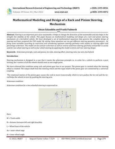
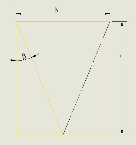
Ackermancondition: Ackermanconditionforatwowheeledsteeringisexpressedas: WHere:=Trackwidth B=distancebetweenleftandrightknuckles L=Wheelbaseofthevehicle =outerwheelange = wheelangle
Journal | Page
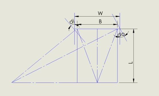
Mathematical model for the rack and pinion steering: Herearethelistofvarioussteeringparametersinthecaseofrackandpinionsteering: travel
aWhere:=steeringarmlength t=tie rodlength B=Trackwidth j+2r=rackballjointcentertocenterlength β=ackermanangle h=distancebetweenfrontaxisandrackcenteraxis q=
Engineering and
©
……………………………………….(1)
Volume: 09 Issue: 03 | Mar 2022 www.irjet.net p-ISSN: 2395-0072 2022, IRJET | Impact Factor value: 7.529 | ISO 9001:2008 Certified 380
International Research Journal of Technology (IRJET) e ISSN: 2395 0056
Usingthebasiclawsoftrigonometrywearriveatthefollowingequation: cotdo cotdi=B/L
Thisistheackermanconditionforatwo wheeledsteering. When ackerman condition is satisfied in a steering mechanism the vehicle takes a turn. The inner wheel needs to be turned morethantheouterwheelinorderfortheconditiontobesatisfied.
ofrack
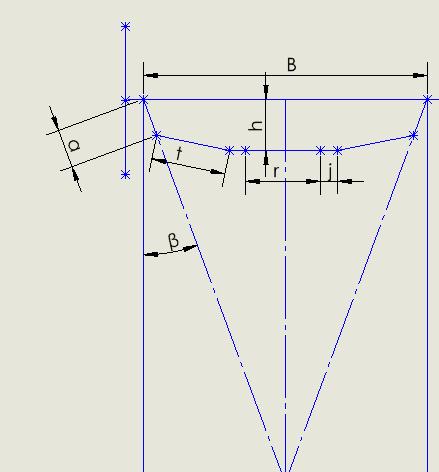
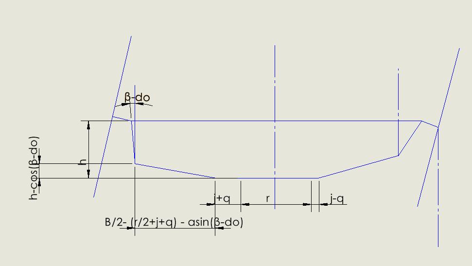
International Research Journal of Engineering and Technology (IRJET) e ISSN: 2395 0056 Volume: 09 Issue: 03 | Mar 2022 www.irjet.net p-ISSN: 2395-0072 © 2022, IRJET | Impact Factor value: 7.529 | ISO 9001:2008 Certified Journal | Page381 Nowthemathematicsinvolvedinwritingalltheequationsisjustthepythagorastheorem Equationfortoe zerocondition: t2 =[{B (r+2j)}/2 asinβ]2 +[h acosβ]2……………………………………………………(2) Equationfrominnerwheelgeometry
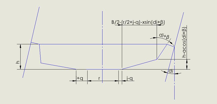
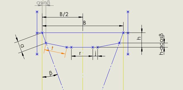
t2 =[B/2 (r/2+j q) asin(di+β)]2 +[h acos(di+β)]2…………………………………………(3)
3. Ackermananglevalueisfixedbythewheelbase(L)andthetrackwidth(B).
Equationfromouterwheelgeometry: t2 =[B/2 (r/2+j+q) asin(β do)]2 +[h cos(β do)]2……………………………………………….(4)
1. ThevalueofBisfixedbythetrackwidthofthevehicleandknuckletoknuckledistance.
Equations(2),(3)and(4)denotethegoverningequationsofthesteeringmechanism
Volume: 09 Issue: 03 | Mar 2022 www.irjet.net p-ISSN: 2395-0072 © 2022, IRJET | Impact Factor value: 7.529 | ISO 9001:2008 Certified Journal | Page382
Methodology:
2. Foragivenrackandpinionmechanism,thevalueofrandjisknown
International Research Journal of Engineering and Technology (IRJET) e ISSN: 2395 0056
Experimental setup: Thevehicleforwhichwearedesigningthesteeringisabio hybridvehicle.Thespecificationsofitare:
4. Foranygivenvalueofinnerangleturn(di)thevalueofouterangleturncanbecalculatedas: cotdo cotdi=B/Ldo=cot 1(B/L+cotdi).............................(5)
7. Now,wehave3equationsand3unknowns.Wecanobtainalltherequiredvalues.
6. Herethevalueofthesteeringarmcanbefixedasitdependsupontheknuckleandframedesignofthevehicle.
International Research Journal of Engineering Technology (IRJET) e ISSN: 2395 0056 Volume: 09 Issue: 03 | Mar 2022 www.irjet.net p-ISSN: 2395-0072 © 2022, IRJET | Impact Factor value: 7.529 | ISO 9001:2008 Certified Journal | Page383
and
5. Offallthevariablesthathaveappearedintheaboveequations,wehavetocalculatethevalueofa,h,tandq.Wehave threeequationsandfourvariablessowehavetofixoneinordertoobtaintheother.
1. Trackwidth(W)=33inches=83.82cm 2. Knuckletoknucklewidth(B)=25inches=63.5cm 3. Wheelbase(L)=48inches=121.92cm 4. Ackermanangle( =14.6degrees 5. Lengthofrack(r)=6inches=15.24cm 6. Radiusofballjoints(j)=1inch=2.54cm 7. Steeringarm(a)=2inches=5.08cm We are designing the steering for an inner wheel turn of 49 degrees and outer wheel turn of 33 degrees as given by the ackermancondition. Puttingthesevaluesintheaboveequations,weareleftwiththefollowingequations: t2 =[21.6 0.25a]2+[h 0.96a]2………………………………………………………….(6) t2 =[21.6+q 0.89a]2 +[h 0.44a]2…………………………………………………………(7)
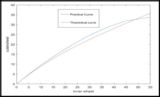
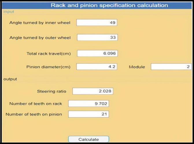
Inordertocheckweatheroursteeringhavesatisfiedtheackermancriteriaornot,weplotthetheoreticalgraphandcompare itwiththegraphobtainedfromourcalculation. Theoreticalgraphcanbeplottedusing(5)andwecanuse(3)and(4)inorderto plotthepracticalgraphafterallthevalues havebeenobtained. Thisisthecomparisonofoursteeringmechanismwiththeoreticalackerman Calculation and selection of other steering parameters: Apiniondiameterof42mmandmodule2isselectedandthenothercalculationsareperformed: 1. Steeringratio: This is defined as the ratio of total angle turned by steering(left + right) wheel in lock positions to the sum of total steeringangleoftires. Angleturnedbysteeringwheels={360/(��*piniondiameter)}*q=(360/(��*4.2))*360 =166degrees
Uponsolvingthesethreeequations,wegetthefollowingresults:
Steeringratio=Angleturnedbysteeringwheel/(totalangleturnedbywheels) =166/(49+33) =2.028:1
International Research Journal of Engineering and Technology (IRJET) e ISSN: 2395 0056 Volume: 09 Issue: 03 | Mar 2022 www.irjet.net p-ISSN: 2395-0072 © 2022, IRJET | Impact Factor value: 7.529 | ISO 9001:2008 Certified Journal | Page384 t2 =[21.6 q+0.32a]2 +[h 0.95a]2…………………………………………………………(8)
Tie rodlength(t)=8inches= 20.32cm Racktravel(q)=1.2inch=3.048cm Distancefromwheelaxistotierod(h)=2.5inches=6.25cm
3. Calculationofsteeringeffort:
Steeringeffortisdefinedastheefforttobemadebythedriverinturningthesteeringwheel.Thiscanbecalculatedin eitherstaticconditioni.e.whenthevehicleisstationaryandindynamicconditions.Steeringeffortismaximumwhen thevehicleisstationary.
International Research Journal of Engineering and Technology (IRJET) e ISSN: 2395 0056 Volume: 09 Issue: 03 | Mar 2022 www.irjet.net p-ISSN: 2395-0072 © 2022, IRJET | Impact Factor value: 7.529 | ISO 9001:2008 Certified Journal | Page385 2. Numberofteethonrackandpinion: For pinion Numberofteeth=circumference/module=diameter/module=42/2=21 For Numberrackofteeth=(numberofteethonpinion/360)*angleturnedbythesteeringwheel =(21/360)*166 =9.68=10teeth AGUIwasalsodevelopedonMATLABforthecalculationoftheseparameters
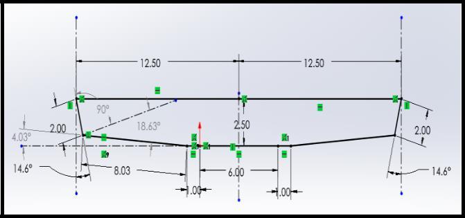
Theabovediagram(alldimensionsininches)couldbeusedforthecalculationofsteeringeffort.
Massofvehicle=142+20(payloadof20kg)+95(withdriverof95kg)=257kg Letssupposetheweightofthevehicleisequallydistributedinallfourwheels
International Research Journal of Engineering and Technology (IRJET) e ISSN: 2395 0056 Volume: 09 Issue: 03 | Mar 2022 www.irjet.net p-ISSN: 2395-0072 © 2022, IRJET | Impact Factor value: 7.529 | ISO 9001:2008 Certified Journal | Page386
Reactionateachtyres=257/4=64.25kg=629.65N
Frictionalforceatthetyres=��*R=.6*629.65=377.79N[taking ��=.6] Weneedaforceof377.79Nonthesteeringarmtoturnthewheels. Forceonthetie rod=377.79/cos(18.4) =398.18N Forceontherack=398.18/cos(4.03)=402.2N Thisforcehastobetransmittedbythepinionthroughthesteeringwheeltotherack. Torqueonsteeringwheel=Torqueonrack=Forceonrack*radiusofpinion=402.2*0.021 =8.4462Nm
Volume: 09 Issue: 03 | Mar 2022 www.irjet.net p-ISSN: 2395-0072
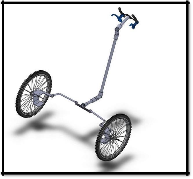
Fig:fullyassembledsteering(designedonSOLIDWORKS)
© 2022, IRJET | Impact Factor value: 7.529 | ISO 9001:2008 Certified Journal | Page387
[3] Aksh Patel, Nandan Bhatt , Mayur Bapu Rawade Department of mechanical engineering Lj institute of engineering and technology ahmedabad, India “Design Methodology and Manufacturing of Rack and Pinion for All Terrain Vehicle”, InternationalJournalofEngineeringResearch&Technology(IJERT) Vol.8Issue06,June 2019
References: [1] DipalkumarKoladia“MathematicalModeltoDesignRackAndPinionAckermanSteeringGeomtery”,InternationalJournal ofScientific&EngineeringResearch,Volume5,Issue9,September 2014
[2] Dr.V.K.Saini*,Prof.SunilKumar,AmitKumarShakya,HarshitMishra “DesignMethodologyofSteeringSystemforAll TerrainVehicles”InternationalResearchJournalofEngineeringandTechnology(IRJET)Volume:04Issue:05|May 2017
Conclusion: The paper above presents the complete design of a rack and pinion steering mechanism for an bio hybrid vehicle. The mathematicalmodelpresentedcanalsobeusedtodesignsteeringforrearwheels.Wecanvarythevalueofthesteeringarm andperformmanyiterationsinordertooptimizethesteeringgeometryandmakeitasclosetotheidealackermangraph.We usedsoftwareslikeMATLAB,FUSION360andSOLIDWORKSfortheproject.
International Research Journal of Engineering and Technology (IRJET) e ISSN: 2395 0056