OPTIMAL GRID GEOMETRY OF A DIAGRID STRUCTURE
Brunda1Post graduate student, Department of civil engineering, University Visvesvaraya College of Engineering, Bangalore University, Bangalore 560056

2Associate Professor, Department of civil engineering, University Visvesvaraya College of Engineering, Bangalore University, Bangalore 560056
Abstract Introduction and advancement of new technologies, materials, structural systems have led to the speedy boom of high rise buildings. The adaptability in architectural design and efficiency ofthestructurehasmadea diagrid structural system a go to structural system for tall building. Structural design of the diagridstructureisdesigned with respect to lateral loads like windandearthquake.Closely spaced vertical column are existing in the framed tube structures whereas, in diagrid structural system the columns are inclined columns on the exterior surface of the building. The wind and earthquake loads are resisted by the action of axial action of the diagonal columns in contrast the framed tube structure where the wind and earthquake loads are resisted by the action of bending of vertical columns. The core in a diagridstructural system can be eliminatedin most of the cases because the lateral shear can be carried by the peripheral diagonals of the building. The modeling and evaluation of structure is executed in ETABS. In this studies, diagrid structures are analyzed and compared to find the optimum angle for various height of thestructureandtostudy the effect of varied angle and shape of the structures. The Models are designed as per Indian standard code IS800:2007 considering all the load combinations.
Key Words: Lateral load resisting system, diagrid structural system, Displacement, Time period
1.INTRODUCTION
Thepopulationisincreasingatahighrate;thelimitedspace hasconsiderablyinfluencedthedevelopmentofresidential area.Thehighcostofland,thedesiretoavoidacontinuous urbanrushhasresultedinthedriveofresidentialbuildings upward.Asthenumberofstoreyinabuildingincreases,the lateral load resisting system turns into greater necessary thanthestructuralsystemthatcanresistgravitationalloads. Lately, the diagrid structural system is used for tall steel structuresduetoitsaestheticpotentialstructuraleffectivity andfurnishedthroughthespecialgeometricconfigurationof the Aestheticsystem.nature
ofthediagridstructuremakesittostand outfromotherbuildings.Theconfigurationandefficiencyof a diagrid system decreases the quantity of structural component required on the façade of the buildings, consequentlyreducestheobstruction ofthe outsideview.
Thestructuralefficiencyofdiagridsystemadditionallyhelps in avoiding interior and corner columns, therefore permittingconsiderableflexibilitywiththefloorplan.
1.1 METHODOLOGY
Step1:Studyingvariousthesisondiagridstructure.
Step2:Generatingtheparametricmodel
Step3:Applyingtheloadonthestructure
Step4:Analyzingthestructure
Step 5: Comparing the models for obtaining the optimum model
Table 1 Specification of the Model
Dimensionofthebuilding 36*36m Area 1296m2
Areaofthecore 324m2 Liveload 4KN/m2 Deadload 2KN/m2 Baylength 9m
Heightofeachfloor 4m Deckslabthickness 90mm
Gradeofconcrete M30 Gradeofsteel Fe345
Dampingratio 5%
Typeofbuilding Important
Importancefactor 1
Typeofsoil medium Seismiczone ZoneIII
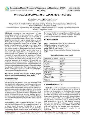
2. BUILDING PARAMETER
TheModelshave36m×36mplandimension.Thestorey height is 4 m. In diagrid structures, pair of braces is positioned at the periphery of the building. The spacing betweentheinclinedcolumnsareprovidedat9malongthe perimeter.Onlygravityloadisconsideredforthedesignof interiorframeofthediagridstructure.Thedesigndeadload istakenas4kN/m2 andliveloadsas2kN/m2.Thedesign earthquake load is computed based on the zone factor of 0.16. The importance factor of 1 and response reduction factorof5isconsidered.Modellingandanalysisofdiagrid structure are carried out using ETABS software. All structural members are designed using IS 800:2007. Secondary effect like temperature variation is not considered.
3. OPTIMUM ANGLE
Thediagonalmemberofthediagridcarriesbothshearand moment. the geometry of the single module plays an importantfunctionintheinternalaxialforcedistribution,as wellasinconferringglobalshearandbendingrigiditytothe structure.Theoptimal angle ofthecolumnsformaximum bendingrigidityandshearrigidityinthenormalbuildingis 90degreesand35degreesrespectively.Itispersumedthat theoptimalangleofthediagridfallsinbetweentheabove two Analysisvaluesis
performed on 12 storey(A), 24 storey(B), 36 storey(C),48storey(D),60storey(E),72storey(F)withthe provision of different angles 41038’(2 module), 60035’(4 module),69029’(6module),74017’(8module),79022’(12 module).
3.1 Top Storey Displacement
AsperIndianstandardcodeIS:456 2000,themaximumtop storeydisplacementshouldnotbemoreH/500,whereHis totalheightofthebuilding.Thedisplacementresultsforall themodelsarewithinthepermissiblelimit
3.2 Time Period
Thetimeperiodisinverselyproportionaltothestiffnessof the structure. Time period depends upon the mass and stiffnessofthestructure.Ifthetimeperiodisless,themodal mass is less but the stiffness of the building is more vice versa.
Incaseof12-storeyand24-storeymodel,thetimeperiodis leastin60degreeswhichsuggeststhatthestiffnessofthe model is at maximum when the diagrid is inclined at the angle60degrees
Incaseof36-storey,48-storey,60-storeyand72-storeythe stiffness is maximum when the diagonal is inclined at an angle69degreesbecausethetimeperiodismaximumat69
Consideringdegrees
thefirsttimeperiodtheoptimumanglecanbe seenbetween60-70degrees
Fig 1: Top storey displacement
In case of 12 storey model and 24 storey model, the optimum angle is found to be 60 degrees. The maximum displacementinboththemodelappearsin41degreesandis almost3timesmorethantheoptimumangle.
Incaseof36 storeymodel,thedisplacementisleastin60 degrees and 69 degrees. The maximum displacement appears in 41 degrees is almost 2times more than the optimumvalue
From the above graph considering the top storey displacement,theangleofdiagridisoptimumintheregion ofangle60°to70
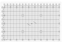
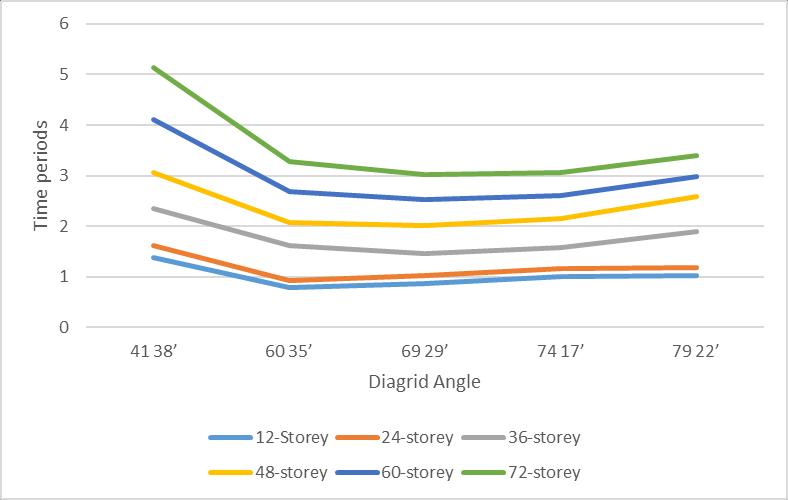
Fig 2: First mode Time period
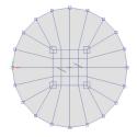
4. SHAPE OF THE STRUCTURE
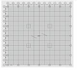
Shapeofthemodelplaysanimportantroleindesigningof the structure. In this project 3 different shapes of square, rectangle and circle. The structure are modelled for same area of 1296 m2. Dimension of Rectangle is 54*24m. Dimension of Square is 36*36 m and circle model has a diameterof42.6m.
Fig 3 Rectangle model
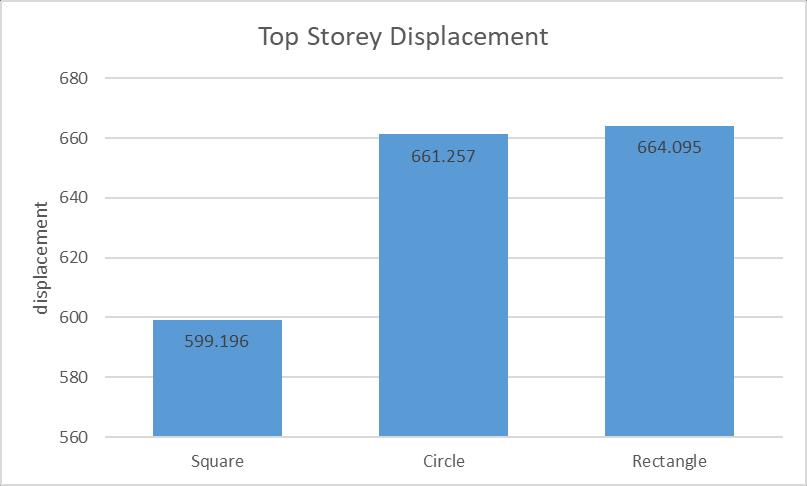
Squaremodelperformedbettercomparedtorectangleand circle structure. Top storey displacement of Rectangle structureis11%morecomparedtothesquaremodeland almost same compared circle structures. Top storey displacementofCirclestructureis10%morecomparedto squarestructure.
4.2 Time period
Squaremodelperformedbettercomparedtorectangleand circle structure. Top storey displacement of Rectangle structureis11%morecomparedtothesquaremodeland almost same compared circle structures. Top storey displacementofCirclestructureis10%morecomparedto squarestructure
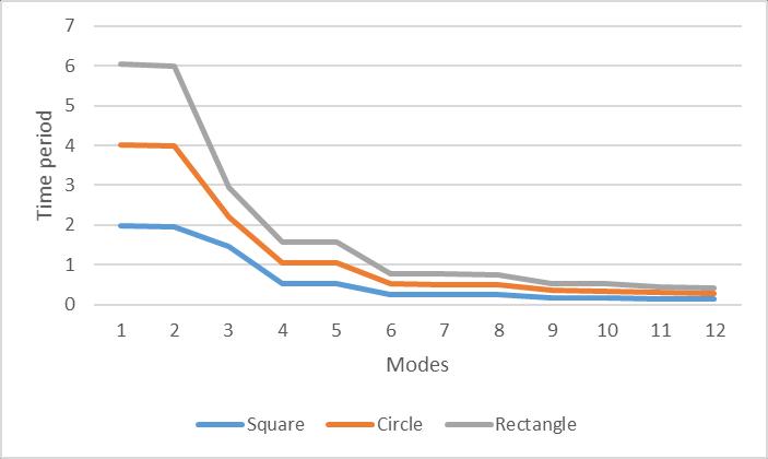
Time period is more in rectangle structure by 0.032 compared to square structure and by 0.02 compared to circle.TimeperiodofCirclestructureis0.012morethanthe timeperiodofsquarestructure.Timeperiodofastructureis indirectly proportional to the stiffness of the structure. Therefore, we can conclude that the square structure has maximumstiffnessandrectanglehastheleaststiffness.
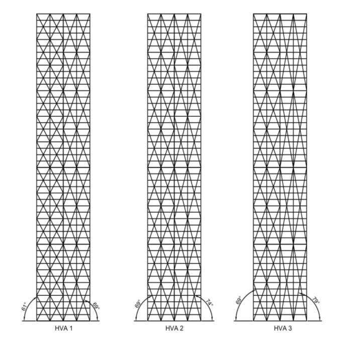
5. VARIED ANGLES
Analysisiscarriedouton3modelswithanglevaryingalong thewidthofthestructureand3modelswithanglealongthe heightofthestructure
VVA1(42,74and79degrees),VVA2(42,69and79degrees) andVVA3(61,69and79degrees)hasanglesvaryingalong theheightandHVA1(61and69degrees),HVA2(69and74 degrees),HVA3(69and79degrees)hasanglesvaryingalong thewidth.
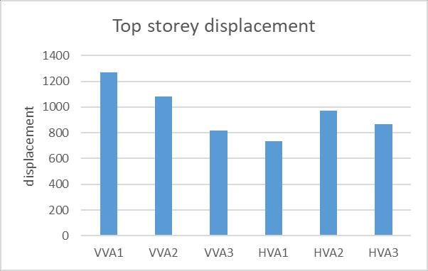
Fig Fig5.1 Top Storey Displacement of Varied Angle
Fig 10 Top storey displacement of Varied angle
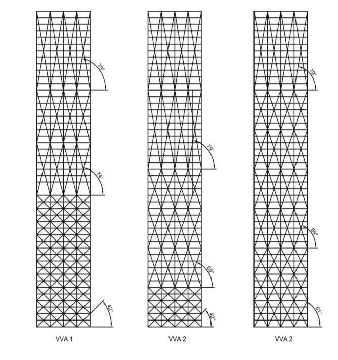
In case of the varied angles along the height, VVA3 performed better compared to other structure. The top storeydisplacementofVVA2is33%morecomparedtothat ofVVA3andThetopstorey displacementofVVA1is55% morecomparedtothatofVVA3Timeperiodisleastinthe model VVA3 hence the stiffness is more in that structure. Fromabovethedatawecanconcludethatthemodelwith moreoptimumanglesperformbetter.
In case of varied angles along the width, HVA1 was performedbetterthantheothertwostructurebecauseboth the angles are in the optimum range. Top storey displacement of HVA2 is 33% more than the top storey displacement of HVA1 and 13% more than the top storey displacement. HVA3 performed better than HVA2. This is duetothefactthatHVA3model hadmorecommonjoints comparedtoHVA2
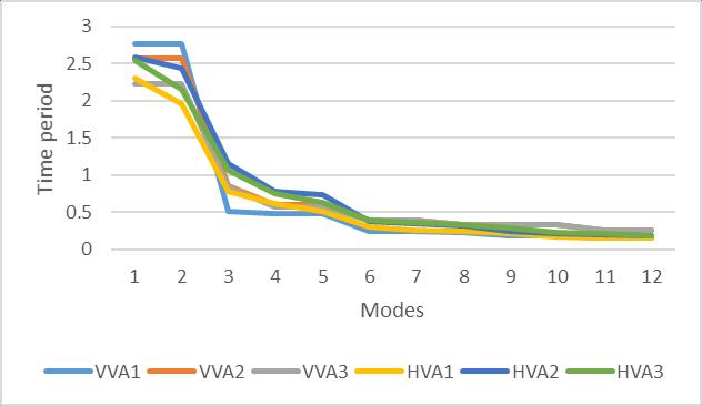
5.2 Time Period of Varied Angle
Fig 11 Time period of Varied angle
Incaseofthevariedanglesalongtheheight,Timeperiodis maximuminVVA1andleastinVVA3.Therefore,wecansay that stiffness is maximum in VVA3 followed by VVA2 and leastinVVA1.
In case of varied angles along the width, Time period is maximuminHVA1andleastinVVA3.Therefore,wecansay that stiffness is maximum in HVA3 followed by HVA2 and leastinHVA1.
CONCLUSIONS
Fromtheaboveanalysiswecanconfirmthat
Itwasfoundthat60degreesisnearoptimalangle for 12 and 24 storey diagrid structures, and 69 degrees for the 48,60 and 72 storey diagrid structures.Incaseof36 storeydiagridstructurethe angle60and69degreesgavealmostsimilarvalues
[4] U.A.Nawale1,D.N.Kakade, “AnalysisofDiagrid Structural System by E Tab”, International Advanced Research Journal in Science, Engineering and Technology, ISSN2393 8021,Vol.4,Issue6,June2017
[5] PoojaLizIsaac,BennetAIpe,“ComparativeStudyof PerformanceofHighRiseBuildingswithDiagrid,Hexagrid and Octagrid Systems under Dynamic Loading”, International Research Journal of Engineering and Technology(IRJET)ISSN:2395 0056Volume:04Issue:05 ,May2017
[6] DivyaM.S.,B.Saraswathy,“ComparativeAnalysisOf High Rise Steel Building With Hexagrid, Diagrid And Conventional Structural System”, International journal of engineering and technology, ISSN: 2395 0056, Volume 4, Issue4,April2017
These results agree with the assumption that the optimalanglebecomessteeperastheheightofthe structurebecomestaller.
Lower angle of 41 degrees were more prone to damagecomparedto other anglesfollowed by79 degrees
Squaremodelperformedbettercomparedtocircle andrectangle
Circle showed minimum displacement and maximumstiffnesscomparedtotherectangle
[7] ManthanI.Shah,SnehalV.Mevada,VishalB.Patel, “ComparativeStudyofDiagridStructureswithConventional FrameStructuresManthanI.Shah,SnehalV.Mevada,Vishal B.Patel”,InternationalJournalofEngineeringResearchand Applications,ISSN:2248 9622,Vol.6,Issue5,(Part 2)May 2016,pp.22 29
[8] AmolV.Gorle,S.D.Gowardhan(2016),“Optimum PerformanceofDiagridStructure”, InternationalJournalof EngineeringResearchISSN:2319 6890VolumeNo.5Issue: Special3,pp:583 585
In case of the varied angles along the height, stiffnessismaximuminVVA3followedbyVVA2and leastinVVA1.
Incaseofvariedanglesalongthewidth,stiffnessis maximuminHVA3followedbyHVA2andleastin HVA1.
The model with more optimum angles perform bettertootherstructure
REFERENCES
[1] Vahid Mohsenian , Saman Padashpour , Iman Hajirasouliha (2020), “Seismic reliability analysis and estimation of multilevel response modification factor for steel diagrid structural systems”, Journal of Building Engineering29(2020),101168
[2] Chittaranjan Nayak , Snehal Walke, and Suraj Kokare,“OptimalStructuralDesignofDiagridStructurefor Tall Structure” , ICRRM 2019 system realibilty, Quality Control,safety,maintenanceandmanagement,pp.263 271,
Giovanni Maria Montuori , Elena Mele, Giuseppe Brandonisio, Antonello De Luca(2019), “Geometrical patternsfordiagridbuildings:Exploringalternativedesign strategies from the structural point of view” Engineering StructuresVolume71,15July2014,Pages112 127
[9] ElenaMele,MaurizioToreno,GiuseppeBrandonisio andAntonelloDeLuca,“Diagridstructuresfortallbuildings: case studies and design considerations” The Structural DesignOfTallAndSpecialBuildings.23,124 145(2014)
[10] Nishith B. Panchal, Vinubhai R. Patel, “Diagrid StructuralSystem:StrategiesToReduceLateralForcesOn High Rise Buildings”, International journal of engineering andtechnicalresearch,ISSN:2319 1163,Volume3,Issue3, April2014
[11] NishithB.Panchal,Dr.V.R.Patel,Dr.I.I.Pandya, “OptimumAngleofDiagridStructuralSystem”,International journalofengineeringandtechnicalresearch,ISSN:2321 0869,Volume2,Issue6,June2014
[12] KhushbuJania,PareshV.Patel“AnalysisandDesign ofDiagridStructuralSystemforHighRiseSteelBuildings”, ELSEVIER,ProcediaEngineering51(2013)92 100
[13] KyoungSunMoon(2008),“OptimalGridGeometry of Diagrid Structures for Tall Buildings”, Architectural ScienceReviewVolume51.3,pp239 251