shouldbeproperlywashedandtestedtoascertainthattotal percentageofclay
S.No
Table
2.3 Coarse Aggregate
Thecoarseaggregatesaregranularmaterialsobtainedfrom rocksandcrushedstones.Theymaybealsoobtainedfrom syntheticmaterial slag,shale,flyashandclayforusein light 20mmweightconcrete.Inthisprojectcoarseaggregateofsizeareused.
Table 3: Test Coarse
S.No Description
1
2.4 Ground Granulated Blast Furnace Slag (GGBS)
Groundgranulatedblastfurnaceslagisaby productfrom theblastfurnacesusedtomakeiron.Theironoreisreduced toironandtheremainingmaterialsfromaslagthatfloatson top of the iron. This slag is periodically tapped off as a moltenliquidandifitistobeusedforthemanufactureof GGBS it has to be rapidly quenched in large volumes of water. ThecostoftheGGBSisthelowcomparetocement. Thishavehighdurabilityandbestreactionissodiumbased alkalinesolutions.
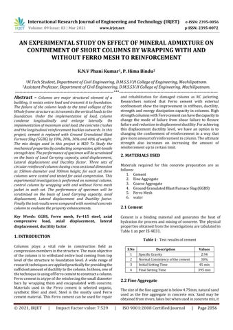
2.5 Ferro Mesh (chicken wire mesh)
Chicken net is made of thin, flexible, galvanized steel with hexagonal openings, many times it is known as hexagonal netting. The shape of wire mesh available in Rectangle, Diamond and Hexagon. It’s look like a chain links, for exampleifanywireischop,itdoesn’tbreaktotallylikein chain link. It may be reverse twisted, straight twisted or doubletwisted.Itisavailable in1inch(2.5cm)diameter,2 inch (about 5 cm) and ½ inch (1.3 cm) Ferro mesh is availableinvariousgauges usually19gauge(about1mm wire)to22gauge(about0.7mmwire).
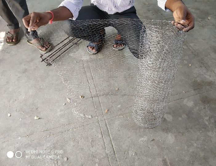
Figure 1: GGBS
Figure 2: FerroMesh
2.7 Water
Clean potable water was used for making concrete. This project distilled and marine water is used to casting of specimens.Waterfitfordrinkingisgenerallyconsideredfit formakingconcrete.Waterhastwofunctionsinaconcrete mix.FirstlywaterpermissiblelimitsobservedIS:456 2000.
3. TEST AND RESULTS

3.1 Hardened Concrete
Concreteiscastedintocubes,cylindersandprismsasperIS 516recommendationsandcuringshouldbedonefor7days, and28days.Ineachset9specimensaremadei.e.3cubes,3 cylinderforeachconcretemixofM20gradeconcreteadded withGGBSofdifferentproportions.Testperformedinthis researchare:
1. CompressionStrengthtest
2. SplitTensileTest
Theresultsofabovetestaftercuringperiodfor7daysand28 daysaretabulatedbelow
100%OPC
Chart
Table
Chart
Threecolumnspersetarecastedonbasisofoptimumvalues of mix proportion (70% OPC + 30% GGBS) with and without FerroMeshandthedeflectionsofeachcolumnareevaluated using the universal testing machine and those values are represented in below tables and charts. On the basis of winding the Ferro Mesh to reinforcement, columns are classifiedinto
C1 Reinforcement without Ferro Mesh casted with Nominalconcrete
C2 Reinforcement without Ferro Mesh casted with mix proportion(70%OPC+30%GGBS)concrete
C3 Reinforcement with Ferro Mesh casted with mix proportion(70%OPC+30%GGBS)concrete
Figure 3: ColumnDetails
Description Type 1 Type 2 Type 3
Lengthofcolumn 700mm 700mm 700mm ofcolumn 150mm 150mm 150mm
Length bar 650mm 650mm 650mm
Noofbars 4 4 4 Diameterof longitudinalbar 8mm 8mm 8mm Diameteroflateral tie 6mm 6mm 6mm
Spacingbetween Ties 120mmat Ends
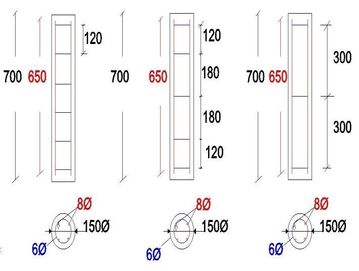
Clearcover 25mm
Table 6: Comparisonofloadvsaxialdisplacementfor uniformandNon uniformspacingwithandwithoutmesh
Load(kN)
Type 1 Type 2 Type 3
C1 C2 C3 C1 C2 C3 C1 C2 C3
0 0 0 0 0 0 0 0 0 0
30 1.5 1 1.2 0.9 1 0.9 1.5 1.3 0.5 60 2.2 1.5 1.6 2 1.6 1.5 2.4 2.1 2.5 90 3.2 2 2.1 2.5 2.2 2 3.2 2.5 3 120 4.2 2.9 2.5 3 3.2 2.7 4.3 3.5 3.2 150 5.6 3.2 3.2 3.6 3.9 3.8 5.3 4 5 180 7.2 4.9 4.5 4.2 4.6 4.7 7.9 6 6 210 8 5.6 5.6 5.6 5.2 5 9 6.8 6.8 240 6.4 7.9 6 6.4 6.2 7 7.9
270 7.5 9.2 7.6 8 9.5 9 300 10 8 8.4 11 330 9.2 12.5 360 10.4 390 11.2
Table 7: ComparisonofloadvsLateraldisplacementfor uniformandNon uniformspacingwithandwithoutmesh
Load(kN)
Type 1 Type 2 Type 3
C1 C2 C3 C1 C2 C3 C1 C2 C3
0 0 0 0 0 0 0 0 0 0
30 0.06 0.01 0.05 0.1 0.05 0.04 0.6 0.6 0.7 60 0.1 0.013 0.4 0.19 0.1 0.3 0.95 0.96 1 90 0.3 0.15 0.9 1.1 0.2 0.8 1.3 1.2 1.4 120 0.7 0.2 1 1.3 0.4 1.12 2.1 2.4 1.5 150 1.2 0.6 1.3 1.5 0.6 1.2 2.9 2.9 1.9 180 2.1 0.9 1.5 1.7 1.1 1.26 3.6 3.2 2.1 210 2.5 1.2 1.9 1.9 1.5 1.6 4 3.9 2.9 240 1.8 2.6 2.1 1.8 1.8 4.3 3.6 270 2 2.7 2.2 2 4.9 3.9 300 2.8 2.6 2.3 4 330 2.6 4.9 360 2.85 3 8:
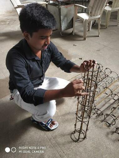 Figure 4 Reinforcement
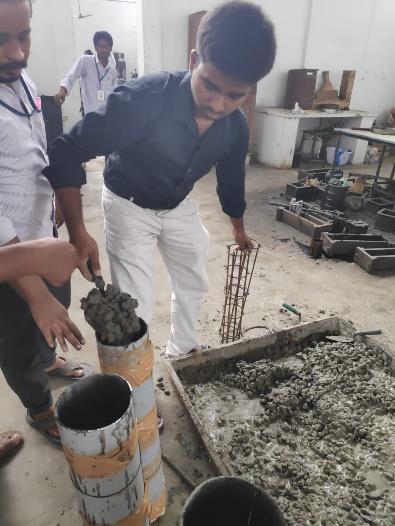
Figure 5 CastingofColumn
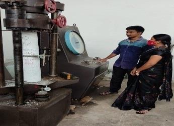
Figure Testingof inUTM
Figure 4 Reinforcement
Figure 5 CastingofColumn
Figure Testingof inUTM
5. CONCLUSIONS
The following main conclusions were drawn from the experimentalresultsobtainedthisstudy:
Inthisproject,wecansaythatloadcarryingcapacityof the column increases with decrease in lateral reinforcement.
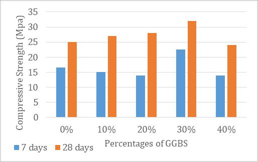
By comparing the test results of cubes, the optimum percentage (70%OPC+30%GGBS) of compressive strength attained is 27.49% higher than the conventionalconcretefor28daysofcuring.
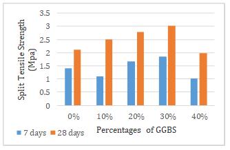
Bycomparingthetestresultsofcylinders,theoptimum percentage (70%OPC+30%GGBS) of Split Tensile strength attained is 43.80% higher than the conventionalconcreteor28daysofcuring.
At 120mm uniform spacing without Ferro mesh, Ultimate crack load of optimum concrete column attained is 28.57 % more than the conventional concretecolumn.
At 120mm uniform spacing, Ultimate crack load of optimumconcretecolumnwithFerromesh,attainedis 11.11 % more than the optimum concrete column withoutFerromesh.
Spacingof120mmatends&180mmatmiddlewithout Ferromesh,Ultimatecrackloadofoptimumconcrete column attained is 25 % more than the conventional concretecolumn.
Spacing of 120mm at ends & 180mm at middle, Ultimatecrackloadofoptimumconcretecolumnwith Ferromesh,attainedis30%morethantheoptimum concretecolumnwithoutFerromesh.
At 300 mm spacing center to center without Ferro mesh,Ultimatecrackloadofoptimumconcretecolumn attained is 28.57 % more than the conventional concretecolumn.
At 300 mm uniform spacing, Ultimate crack load of optimumconcretecolumnwithFerromesh,attainedis 22.22 % more than the optimum concrete column withoutFerromesh.
Ductilityismore,whencomparedtodifferentspacing ofcolumnsanditsfactoris4.14at120mmatendsand 180mmatmiddlespacingwithFerromesh.
Theenergyabsorptioncurveofcolumnconfinedwith Ferromeshat120mmatendsand180mmatmiddle spacingismorethanthatofconventionalcolumn.
Fromthemodeoffailureof columnsitwasobserved thatthelongitudinalcracksareformedatthetopand bottomendsoftheshortcolumns.
Thezoneofruptureisobservednearoneforthheight ofthecolumneitherfromtopandbottom,thislength decreases with decrease in spacing of lateral reinforcement.
REFERENCES
[1] Effect of confinement on behavior of short concrete columnbySyedWasimNRazviandM.Gshaikh2018 563 570
[2] GGBS effects on compressive strength by partial replacement of cement concrete by Azmath Ali Phul, Muhammad Jaffer Memon, Syed Naveed Raza Shah, AbdulRazzaqueSandhu2019 03091299.
[3] ACIcommittee549.Guideforthedesign,construction andrepairofFerroCement.ACIstrutj1988;85:325 51.
[4] SengottianK,Dr.jagadeeshanK.Retrofittingofcolumns withRCjacketinganexperimentalbehaviour.Journalof theoretical and applied information technology 2013; 56:349 54
[5] RathishK,OshimaT,MikamiSandYamazakiTSTUDIES ONRCandFerroCementjacketedcolumnssubjectedto simulated seismic loading ancient journal of civil engineering2007;8:215 25.
[6] AbidASapplicationsoffibrocementinstrengtheningof unreinforcedmasonrycolumns.Internationaljournalof geology;2011:5:21 27.
International Engineering Technology ISSN: 2395 0056
Volume: 09 Issue: 03 | Mar 2021 www.irjet.net ISSN: 2395 0072
[7] Kazemi Mohammed T, morshed R.SESIMIC shear strengtheningofRCcolumnswithFerroCementjacket. Cementandconcretecomposits2005;27:834 42.
[8] MouradS.M,ShannagM.J.Repairandstrengtheningog unreinforced concrete square columns using ferrocement jackets. Cement & concrete composites 2012;34:288 94.
[9] barrera A.C, Bonet J.L,Romero M.L, Fernandez M.A. Ductilityofslenderreinforcedconcretecolumnsunder monotonicflexureandconstantaxialload,Engineering structures2012;40:398 412.
[10] MamariaAliM.HarrisHarryG,HamidAhmadA.Scanlon A. Ductility evaluation for typical existing R/C bridge columns in the eastern USA. Engineering structures 2005;27:203 12.
[11] Fukumoto Yuhshi. Reduction of structural ductility factorduetovariabilityofsteelproperties.Engineering structures:2000;;22:123 27.
[12] Oehlers D.J, Griffith M.C. Mohamed Ali M.S Ductility components and limits of FRP plated RC structures. Constructionandbuildingmaterials.2009;23:1538 43