Analysis Of Earthquake Resistant Structure By Base Isolation Method

Prof. Anjali Palheriya1 , Mr. Gaurav D. Dhumane 2 , Mr. Shreyas Kotangale 3 , Mr. Ratndip More 4 , Mr. Vikki Singh Rawate 5 , Mr. Suprit Badwaik
1Assistant Professor, Department of Civil Engineering, Guru Nanak Institute of Technology, Nagpur, Maharashtra, India.

23456UG Students, Department of Civil Engineering, Guru Nanak Institute of Technology, Nagpur, Maharashtra, India.
Abstract: Researchers have conducted various important studies on the base isolation system, whichhas been fully accepted in the engineering community as an earthquake resistant design tool. Today, a full scale shake table test is being conducted to test the different features of different isolators. The present review outlines the literature and theoretical aspects of this system. Additionally, the research papers examine the effectiveness of various isolators and their applicability. The review paper's main objective is to focus on different types of isolators and provide useful guidelines to makeappropriate choices from a large number of available isolators.
Key Words: baseisolation,seismicanalysis,Leadrubberisolator,E TABS,storyshear.
INTRODUCTION
Severalpreventivemeasures can betaken asper standardscientific guidelines to prevent the effects of earthquakes and minimize their effects. In earthquake prone areas, these measures may prevent deaths and property damage. There is a need to educate the masses about standardconstruction measures in earthquake prone areas to keep them from getting injured by disasters. In some papers, the authors also discuss the effectiveness of different isolation methods and the applicabilityofeach.Itsmainpurposeistodescribeanoverviewofthehistoryofisolatorsandprovideusefulguidelinesto assistinmakingappropriatechoicesamongthewidevarietyofisolatorsavailable
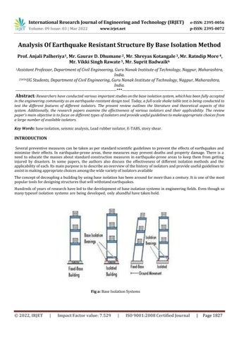
Theconceptofdecouplingabuildingbyusingbaseisolationhasbeenaroundformorethanacentury.Itisoneofthemost populartoolsfordesigningstructuresthatwillwithstandearthquakes.
Hundredsofyearsofresearchhaveledtothedevelopmentofbaseisolationsystemsinengineeringfields.Eventhoughso manytypesof isolation systems are being developed, only ahandfulhavetakenhold.
Fig a: BaseIsolationSystems
International ISSN: 2395 0056 09 Issue: 03 | Mar 2022 ISSN: 2395 0072
METHODOLOGY:
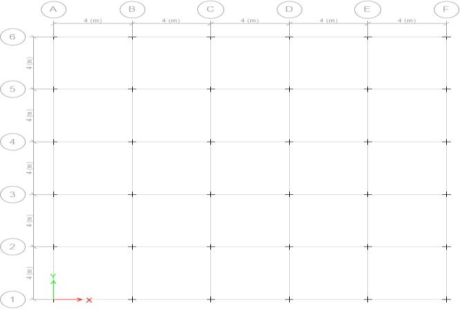
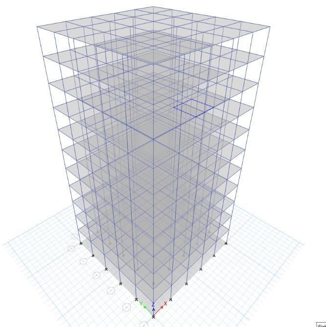
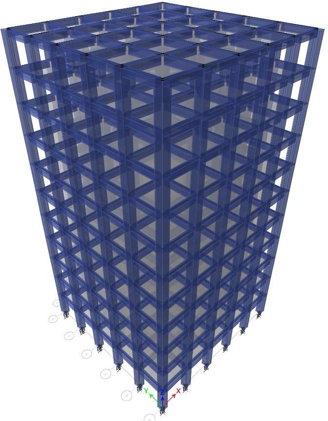
Inthisproject,wehaveusedaG+10storybuildingwiththesamefloorplanwith6bayshavingthesamelengthsof4 m along thelongitudinal and the transverse direction as shown in the figure.Thisbuildingis designed as per the IS Code1893(Part 1):2002forPracticeforSeismicResistant.Designofbuildingsstoryheightsofbuildingsisassumedto beconstantincludingthegroundstory. Thebuildingsaremodeledusingsoftware“ETABS”.
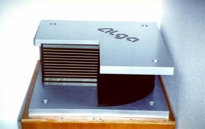
Base Isolator
International ISSN: 2395 0056
Volume: 09 Issue: 03 | Mar 2022 www.irjet.net ISSN: 2395 0072
A lead plug is forcedintoa preformedholein an elastomericbearingtoproducelead rubberbearings. Intheevent of highlateralloads,theleadcoreprovidesrigidityunderserviceloadsandenergydissipation.Alead rubberbearingisstiff both laterally and vertically when subjected to low lateral loads, such as those produced by a minorearthquake. The lateralstiffnessoftheleadplugiscausedbyitshighelasticstiffnessanditsverticalrigidity.Inadditiontocombining rigidityandhighserviceloads,lead rubberbearingshaveotherimportantbenefits.
Fig. c:TypicalLeadRubberBearing

International Engineering Technology ISSN: 2395 0056
Description of Building:
Typeofstructure:multi storyresidentialbuilding.
Numberofstories:11(G+10).
Floorheight:3.5m.
SeismiczoneIII(IS1893(part1):2002).
MaterialsConcrete:(M30)andReinforcement(HYSD500).
Bay sizes in the X direction: 4m, 4m, 4m,4m, 4m&4m 6bays.
BaysizesintheZ direction:4m,4m,4m,4m,4m&4m 6bays.
Column800x800mm(forallcolumns).
Beam600x500mm(forallbeams).
Typeofsoil:mediumsoil.
ResponsespectrumasperIS1893:2002
Loading Details
DeadSelfLoad:weightofstructure=1kn/m External thicknessofwall=230mmInternal thicknessof wall=115mmParapetwall=125mm
LiveLoad:
1. AllFloor=2.5KN/m.
2. EarthquakeZone=ZoneIII.
3. ZoneFactor=0.16.
4. EarthquakeResistanceDesignofStructure=IS1893(Part1)2002.
5. SafeBearingCapacityofSoil=250KN/m3 .
6. Floors=G.F.+10UpperFloors.
7. GroundFloorHeight=3.5m.
8. AssumedThicknessofWallExternalwall=230mmInternalwall=115m.
9. GradeofConcreteforcolumnandother=M30.10.GradeofSteel=HYSDFe500.
Volume: 09 Issue: 03 | Mar 2022 www.irjet.net ISSN: 2395 0072 Impact Factor value: 7.529 ISO 9001:2008
FordesigningthebaseisolatorfollowingdatashouldbeinputintoETABS
RotationalInertia1 0.2180 KN/m
ForU1EffectiveStiffness 1316191.49 KN/m
ForU2&U3Effective Stiffness 4013.432 KN m
ForU2&U3Efficient Damping 0.05 Percent
ForU2andU3 distancefromend J 0.0032 M
ForU2&U3Stiffness 36981.77 KN/m
ForU2&U3Yield Strength 145.203 KN
METHODOLOGY OF WORK:
1. ThefirststepofthisprocedureistoinitializetheStandardCodesandCountryCodes.
2. Creation of Grid points & Generation of structure. As soon as ETABS opens, we select a new model, and a window appearswherewecanenterthegriddimensionsandstorydimensionsofourbuilding.
3. Definingtheproperty Inthiscase,thematerial propertyhad beendefinedfirstbyselectingdefine menumaterial properties.
4. Inthiscase,thematerialpropertyhadbeendefinedfirstbyselectingdefinemenumaterialproperties.
5. Forstructuralcomponents(beams,columns,slabs)weaddnewmaterialsandgivespecificdetailsin thedefinition Thenwedefinesectionsizebyselectingframesectionsandaddingthenecessarysectionsforbeams,columns,etc.
6. Assigning the Property Now that we have defined the property, we draw the structural components using the commandmenu.Wedrawalineforbeamsandcreatecolumnsinregionsforcolumnstoassignthepropertiestothe beams and columns. Assigning Supports Keeping the selectionat the base of the structure and selecting all the columns,weassignedsupportsbyselectingthejoint/frameRestraints(supports)optionintheassignmenu.
7. DefiningloadsinETABSAllloadconsiderations arefirstdefinedandthenassigned.InETABS,the loadsaredefined using the static load cases commandfromthedefinemenu. Thesoftwareassignsdeadloadsbasedonalltheloadsfor externalwalls,whileinternalwallsarehandledautomaticallybythesystem.
8. AssignmentofLiveLoadsareassignedseparatelyfortheroofandflooroftheentirestructure.
9. AssignwindloadsaredefinedandassignedasperIS8751987PART3bygivingwindspeedandwindangle.
10.Bygivingthezone,soiltype,andresponsereductionfactorin Xand Ydirections, seismicloadsaredefined and assignedaccordingtoIS1893:2002.
11.AssigningloadcombinationsUsingtheloadcombinationscommandinthedefinemenuautomaticallygenerates loadcombinationsforeachcodechosen.
12. Analysis After we have completed the above steps, we have run an analysis and checked for errors comparison graphsareformed.
TheLRBparametersarederivedfromtheisolationdesignprocedureandassignedtotherequiredfieldsofLRBformulation. Afterananalysiswithafixedbase,theLRBtechniqueisolatesthebase tomakethestructureearthquakeresistant.Hence its LRBparametersarefoundfromtheisolationdesignprocedureandassignedtotherequiredfieldsofLRBformulation.
STOREYDRIFT
fixedbase isolatedbase
FIGNO1.StoreyDrift
Figno1showsthevariationofstorydriftatthedifferentstorylevels
frequencyincyc/sec
fixed base isolated base
Figno2.Modalperiodsandfrequencies
Fig no.2 shows the frequency (cyc/sec) mode shape graph its seen the frequency has reduced due to the insertion of the baseisolatorofthebuilding.
Maxstoreydisplacementin(mm)x direction
fixed base in x isolated base in x
Figno.3Maximum
Figno.3
CONCLUSION:
a. Analysis of the structure is done using a fixed base and a different base isolator. This study compares different parameterssuchasfrequency,baseshear,displacement,andstorydriftwithandwithoutbaseisolation.
b. Whencomparedtofixedbasemodels,storydriftisreducedatthehighestfloorsofthebuildingwithbaseisolators. c. Incomparisonwithfixedbasebuildings,thefrequencyofbase isolatedbuildingshasdecreased. d. Astheheightofthestructureisincreased,thedisplacementofthebaseisolatorincreasescomparedtothefixedbase. e. This data indicates that the damage to the base isolated structure will be less than the damage to thefixed base structure.Asaresult,thestructurecanbeoccupiedimmediatelyaftertheearthquake. The isolated base structure will be less damaged than a fixed base structure based on the above data. This allows immediateoccupationofthebuilding.
f. Comparingisolatedandnon isolatedbuildings,wecanconcludethatisolatedbuildingsperformbetter.
REFERENCES:
[1] Donato Cancellara, Fabio de Angelis,” assessment and dynamic nonlinear analysis of different base isolation systemsforamulti storyRCbuildingirregularinplan”Elsevier,computers,andstructures,(2016).
[2] S.d.darshaleandn.l.shelke,”seismicresponsecontrolof
[3] r.c.c. structure using base isolation”, international journalof research in engineering science and technology, vol.2, no.1,(2016).
[4] J. Enrique luco,” effects of soil structure interaction on seismic base isolation “elsevier, soil dynamics and earthquakeengineering,pp166 167,(2014).
[5] Y.Liandj.Li,”baseisolatorwithvariablestiffnessanddamping:design,experimentaltesting,andmodeling”,23rd australasianconferenceonthemechanicsofstructuresandmaterials(acmsm23)(2014).
[6] M.k. shrimali1, s.d. bharti2, s.m. dumne3 arumairaj2, “seismic response analysis of coupled building involvingMr damperandelastomericbaseisolation”,ainshamsengineeringjournal6,pp457 470,(2015).