4barlinkmechanismtomaintainanearlyhorizontalchassis over considerable forms of undulating terrains. The suspension movement is controlled by an IMU (Inertial MeasurementUnit)whichrelaysattitudeinformationtothe microcontroller which processes this data and relays instructionstothesystemofservomotors,which helpsin controlling and moving the link mechanism to attain a perfectlyhorizontal chassis.Inadditiontoextraterrestrial expeditions, there has been a surge in military, energy productionprojectswhichdemandasuspensionsystemthat isnotsophisticatedbutatthesametime,effective.Withthe helpofelectronicsandsimplemechanics,smarter,lighter, effective,andeconomicalsolutionsforalargerspectrumof systemscanbeachieved.
Key Words: Active suspension, horizontal chassis, links, electronics,cost effective,etc.
Abstract The present study is a proposition of a novel suspension system that is intended to be of great use in the field of autonomous or manned exploration primarily on extra terrestrial planets. This new approach to suspension systems is fully electronic and uses negative feedback to stabilize the chassis. This research article attempts to let the readergothroughthe designprocessforthewholesuspension system, including link design, dimensioning, electronic component selection, and finally, the embedded C code to attain the desired result. The reasons for choosing these parameters are well addressed in the work. Multiple tests were performed on a prototype that was built during this project on a track that simulated undulating surfaces for the robot to move on. Kinematic and structural analyses were carried out to ensure the prototype could perform as desired. These tests were constantly monitored using the open source software, Processing, which gave real time readings for the attitude of the chassis. The chassis model was drawn on OpenGL for easy visualization of the rolling, pitching, and yawing of the chassis. Multiple tests resulting in lots of code tweaks have ultimately resulted in the fulfillment of the objective.
International Research Journal of Engineering and Technology (IRJET) e ISSN: 2395 0056 Volume: 09 Issue: 03 | Mar 2022 www.irjet.net p ISSN: 2395 0072 © 2022, IRJET | Impact Factor value: 7.529 | ISO 9001:2008 Certified Journal | Page1738

(S.T.A.R.S.S) Kushal Modi1 , Neel Pednekar2 , Danish Natraj3, Vikas Pathak4, Krishna Gaikwad5 1,2,3,4Undergraduate Student, Dept. of Mechanical Engineering, Thakur College of Engineering and Technology, Mumbai, Maharashtra, India 5Assistant Professor, Dept. of Mechanical Engineering, Thakur College of Engineering and Technology, Mumbai, Maharashtra, India ***
Asuspensionsystemisalinkbetweenthewheelsandthe bodyofavehicle.Itmaycompriseshockabsorbers,springs, andlinkages,allarrangedindiversewaysdependingonthe purposetheyarebeingutilizedfor.Overthepastdecades, numerous and distinctive changes have been made and advanced technologies keep coming through. Most of the suspension systems succeed and fulfill the objective they have been proposed for but there aren't as many mechanisms that guarantee an unwavering chassis. With moderndevelopmentsinwarfare,spaceexplorations,and automobiles,suchamechanismismuchneeded.Aftermuch researchandanalysis,wehavecomeforthwithasystemthat applies the fundamentals of mechatronics to remotely control a vehicle's suspension. Unlike the current market leaderssuchastheMRfluid[1],pneumatics,andhydraulic based systems, this one would function with the use of microcontrollers,gyroscopes,andaccelerometers.Itwould sensedatafromitssurroundingsandthenwiththehelpofa series of programs, reciprocate and allow the body to be stable.Suchasystem,whenimplementedonalargerscale couldprovetobeverypragmatic.
An ideal suspension system would be the one that is the most efficient and relatively cheaper. When working on a project,thefirstthingtokeepinmindisthecostwhichisto bekeptminimalwithouthamperingitseffectiveness.
Withplanetaryexplorationbecomingamajoraimofallthe Superpowersintheworld,newerinnovativeandeffective designs are wanted to travel on unknown terrains with safetyassured.Unseenandunexploredterrainsposeagreat threat to vehicles movement and its components. Many designs are currently being researched upon and many simple yet very effective solutions like the "Rocker Bogie Mechanism"[10][12]havesurpassedallcomplicationsandhave becomethealmostidealsolutionforplanetaryexploration. Despite such mechanisms, there still exists the dream of fluid like movement on rough terrains at a comparatively lowerexpense.Wehavedecidedtogowithanindependent, centrally controlled suspension system that relies on individualmovementsofthewheelstoavoidrollinstability. A centrally controlled suspension means that the "brain", that is, the microcontroller installed, controls the movements of the wheels depending upon the input parameters.Weplantointroduceasimpleyetcutting edge roboticsuspensionsystemthatcanbemadebymodifyinga
1.2 Problem Statement
Smart Terrain Adaptive Robotic Suspension System
1. INTRODUCTION
1.1 Background
simplestabilityAnewmechanismtoovercomerollhasmadeusthinkaboutaapproach.
6. ChungKiePanshuoLi,JamesLam,Cheung Multi objective control for active vehicle suspension with wheelbasepreview[3]
1.3 Objectives
1. Stabilizesthechassistomakeitalmosthorizontal, withaverysmalldegreeoferror.
4. Cutdownthemaintenance related.
5. Formoreloadtransfer&response.
2. LITERATURE REVIEW
3. The robot must be able to go over both smooth undulatingsurfacesandsharpobstacles.
2. Enhanceefficiency.
4. Kazuo Tani, Osamu Matsumoto, Shuuji Kajita, Nobumasa Shirai WheeledRobots to Overcome Ground Unevenness in ConstructionAreas
A multi functioning bot with 3 climbingperformthinkdifferentmechanismshasmadeusoveramechanismthatcanmultipletasksincludingstairs
Thenewsuspensionsystemcanbearealbreakthroughin the field of robotic suspension systems. It would be a modification and an improvement on previously existing suspension systems and hence be more effective. The suspensionwillhelpimprovemobilityondifficultterrains formilitaryandspaceexplorationactivities.Thissuspension system can be implemented on various kinds of wheeled bots like the ones which have robotic arms or other modificationsandcanresultinanevenmoreversatilerobot vehicle.Consideringourproject'sdeliverables,itcanbean upgrade as compared to previous systems. The use of mechanical links as well as an automated system is somethingthathasnotbeenexploredtotheutmostandit could lead to further developments in the proposed field. Thecodingoftheprogramandobtainingthebestmaterials tomaximizethepotentialofthisstudyisahurdlebutitcan beovercomewithaproposresearchanddiscussions.
5. AdibiAsl,H.,Rideout,G Using lead vehicle convoyactivepreviewresponsetogeneratefunctionsforsuspensionofvehicles orimplementedreadingdeflectionsmathematicallyalAsimilarapproachtoPanshuoLiet[6].Exceptawholeconvoywasmodeledandintireofonewerefortheother.CanbewhenweuseCOBOTSswarms.
Front wheelmovementswereused asinputstostabilize.Thisgivesus the ability to add pseudo wheels whosemovementswecantrack
•There are 2 kinds of suspension systems active and passive. While passive suspension systems are purely mechanical,activesuspension systemsare interfaced with plentyofsensorsandelectronicsforhigherprecision.Since oursuspensionsystemhasalotofelectronicsinvolved(for higheraccuracy),itfallsunderactivesuspensionsystems
2. BMW DynamicDrive Employs the use of sensors to becausecreatesdetectthemovementofwheelsandcounterforces.Ruledoutofcost.
1. Yuxin Zhanga, Xinjie Zhanga, Min Zhana, Konghui Guoa, Fuquan Zhaoc, Zongwei Liu Study on a novel hydraulic vehiclessuspensionregenerativepumpingfor itsabsorbHydraulicactuatorswerechosentoshock.Butruledoutduetocost
1.4 Scope of project
Table 1: Tabulatedfindingsfromrelevantresearch aroundtheworld
International Research Journal of Engineering and Technology (IRJET) e ISSN: 2395 0056 Volume: 09 Issue: 03 | Mar 2022 www.irjet.net p ISSN: 2395 0072 © 2022, IRJET | Impact Factor value: 7.529 | ISO 9001:2008 Certified Journal | Page1739
Aninnovationinanyfieldrequiresaproperstudyofexisting technologieswhichiswhyamajorportionofthetimeofthis projectwasdedicatedtotheliteraturesurvey.Thishelpedus in understanding various current technologies, their precision, advantages, and disadvantages. The following table is a list of relevant published, patented, and unpublishedresearcharoundtheworld.
3. Karl Iagnemma, Adam Rzepniewski and Steven Dubowsky Control of Robotic TerrainSuspensionsArticulatedVehicleswithActivelyinRough
Sr No. Title Relevance
Tocopeupwe'vecomeupwiththemechanismthatweaim toachievewouldbefeasibletobuildatareasonableexpense andproducemoreeffectiveresults.
ConclusionsfromLiteratureSurvey
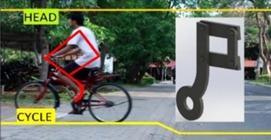
We began by choosing an appropriate design for the link mechanism[4].Someofthemechanismsthatwereprominent afterdiscussionswere
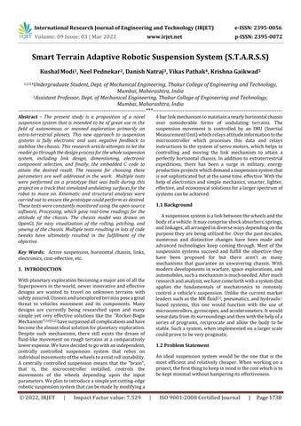
The(Fig.3(a)&(b))designsshowthedisplacementofthe linkwhenitapproachesabumpandaditchrespectively.
•Mostoftheactivesuspensionsystemsareveryexpensive and require a lot of processing power. The suspension systems involving hydraulics, pneumatics, and linear actuators are very expensive as the components are very costly.
Certified Journal | Page1740
Fig 1:TypesofLinks
p
o Modified parallel four bar linkage [Fig. 1(c)]
Volume:
value: 7.529 |
•Purely kinematic based suspension systems are not preciseenough,thereforeacontrolledkinematicsuspension systemwouldbeperfect.
The basic working principle of each system was studied individuallyfollowedbytheanalysisoftheflawsineachof them.Afterdiscussion,wecameupwithamodifiedparallel four barlinkmechanism.Thenmovedontothesimulationof ourmodelintheSOLIDWORKSsoftwarefollowedbyANSYS.
Research Journal of
•The current near perfect solutions like the BMW's dynamicdrive[2] work well forreallysmall vibrationsand bumps.Thesuspensionsystemswhichcanovercomelarge bumpsarenotpreciseenoughwhichgivesusourproblem statement.Weneedtocomeupwithahigh precisionsystem thatcanovercomelargebumps.
Afterthisstep,theElectroniccomponentswerechosenand themicrocontrollerwasinterfacedwiththeIMUandservos. Primitivealgorithmsandcodeswerewrittenandtestedwith suitablemodifications.
© 2022, IRJET | Impact
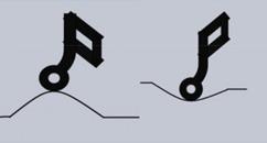
Fig -2:Cyclingprofilecomparedtothelink
3. METHODOLOGY
(IRJET) e
Westartedbyanalyzingvarioussuspensionsystemsthatare currently used following which a detailed study of the evolutionofsuspensionmechanismswasdonetoknowhow eachofthemworked.
4.1 Bio Inspired Link
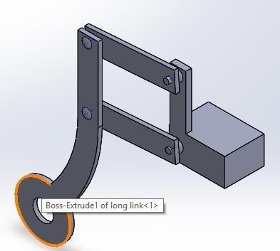
4.2 Modelling
International Engineering Technology ISSN: 2395 0056 09 Issue: 03 | Mar 2022 www.irjet.net ISSN: 2395 0072 Factor ISO 9001:2008
TheD.O.F.wascalculatedusingtheGruebler'scriterion. F=3(N 1) 2P1 P2=1 where, N= 4;P1=4;P2=0
Themovementofthelinkunderuneventerrainisillustrated asbelow:
o Alaid backbentlink1degreeoffreedom arm[Fig.1(a)]
Ourprojectinvolvesabio inspiredlinkthatwillbeusedin theplaceofRockerBogiesuspension,whereitisinspiredby the human body. The human body is the most advanced controlsystemintheworldthedesignisinspiredfromthe joints of human limbs under controlled actions like self balancingofourposturewhileridingabicycleunderuneven terrain,etc.
AllthelinksweremodeledandassembledusingSolidWorks. Thesedesignmodificationswerelaterincorporatedbefore the fabrication of the robot. The final model of assembled links (Fig. 4) and robot (Fig. 5) are given below. The tabulatedsummaryofdimensionsismentionedbelow.
•The suspension system must have "auto stabilization"[3] which means it must be able to recover from all sorts of unprecedentedactuationsduetoroughterrain.
and
Fig 3(a) & (b):Displacementofthelinks
4. DESIGN AND ANALYSIS
o Three tire chain supported wheel [Fig. 1(b)]
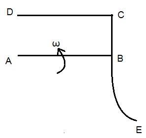
Fig 6(a):LineDiagram
Fig
Thefollowingvelocitydiagramsweredrawnforanalysis
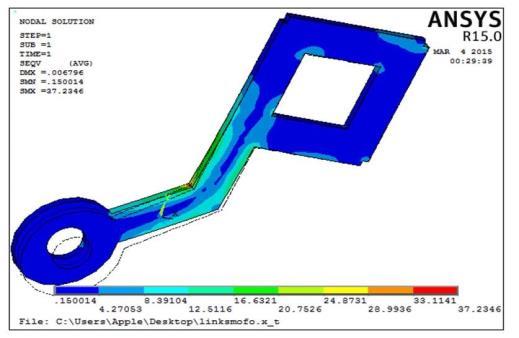
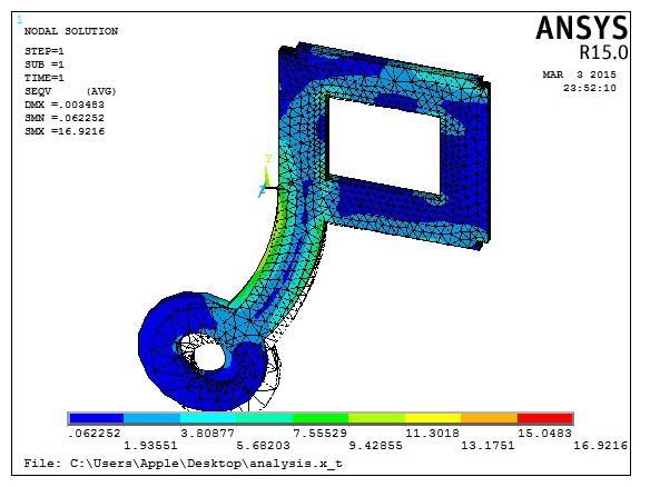
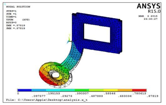
StaticstructuralanalysisusingANSYSwasperformedonthe linktoseehowmuchdeflection(Fig.7)andhowmuchstress isdeveloped(Fig.8)ontheapplicationofadifferentamount offorcestofindoutthepayloadcarryingcapacityofthelink. ThematerialforsimulationisABS(AcrylonitrileButadiene Styrene) as all our links were supposed to be 3D printed, theirpropertiesareasfollows
a)ModulusofElasticity=2000N/mm2
e)ShearModulus=318.9N/mm2
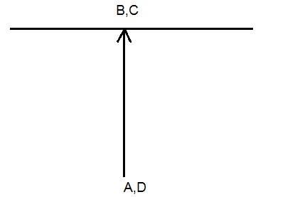
Tofindtherelationofvelocitieswithrespecttothe servoangularvelocity(Fig.6(b))
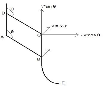
Therefore,linearvelocityoflinkBCiny direction=vxsinθ
d)Poisson’sRatio=0.394
5:AssembledRobot
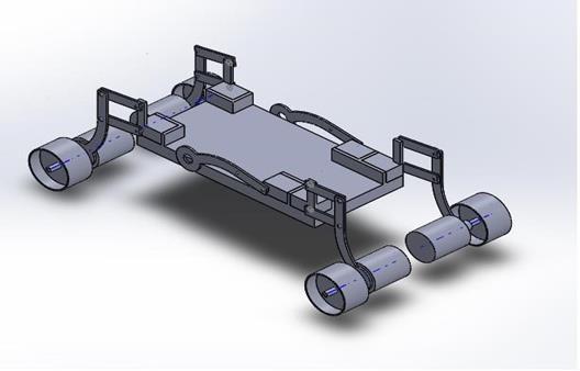
Fig 6(b):VelocityDiagram
Forceapplied=15N, Maximumdeflection=0.87819mm
Kinematicanalysiswasperformedto Ensurethetiremovesinastraightlineandhasno angularvelocitiesareimparted(Fig.6(a))
International Research Journal of Engineering and Technology (IRJET) e ISSN: 2395 0056 Volume: 09 Issue: 03 | Mar 2022 www.irjet.net p ISSN: 2395 0072 © 2022, IRJET | Impact Factor value: 7.529 | ISO 9001:2008 Certified Journal | Page1741 Fig 4:J Link
4.4 Structural Analysis
Displacement Vector Solution for J link
c)UltimateTensileStress=30N/mm2
b)Density=1020Kg/m3
Fig 6(c):LinearVelocityRelation
Linearvelocityoflinkinx direction= vxcosθ
4.3 Kinematic Analysis
FromFig.6(b),Vc,b =0.Thisimpliesthatthereisnorelative motionbetweenpointsBandC.Sincethelinkisrigid,there isalsonorelativemotionbetweenBandE.Anotherdiagram depicting the linear velocities was drawn to find the horizontalandverticalcomponentsofvelocities(Fig.6(c))
5. RESULTS
Forceapplied=15N,
Figure 9:Stressanalysisofinitialbentlink
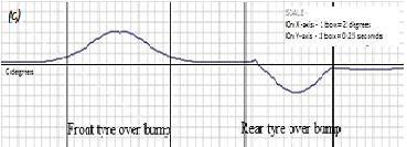
Fig 10(b):ActiveSuspensionSystem
UltimateTensileStress=30N/mm2
International Research Journal of Engineering and Technology (IRJET) e ISSN: 2395 0056 Volume: 09 Issue: 03 | Mar 2022 www.irjet.net p ISSN: 2395 0072 © 2022, IRJET | Impact Factor value: 7.529 | ISO 9001:2008 Certified Journal | Page1742
Additionalpayload=3923gm.
Figure DisplacementVectorforJ Link
UltimateTensileStress=30N/mm2(Designissafe; FOS≈1.77)
Atthisweight,theservomotorsandlinkshadreachedtheir limit and started to deform and twist. This result was consistentwithalltheSimulationsperformedonANSYS.
-7:
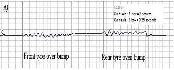
Itcanbeseenthathowthesuspensionsystemiseffective andhowitmaintains0degreesinbothpitchandrollwhen it’llpassoverabump.A real timegraphsofangle(pitch)v/s time were plotted. A comparison of the graphs with the roboticsuspensioninactiveandactiveareshowninFig10 (a)and(b)respectively.
Von Misses Stress Solution for J link
Figure 8:VonMissesStressforJ Link
MaximumStressInduced=16.9216N/mm2
Maximum stress induced (corner) = 37.2346 N/mm2
Robotgm.weight=1845gm
Fig 10(a):InactiveSuspensionSystem
Thedesignisthereforeunsafeforthesameload.
Stress analysis of the initial bent link
There was also static analysis carried out on an alternate linkdesign(conventionallaidbackbentlink)toshowcase theefficiencyofourlinkselection.Thestaticanalysisproved J link is a safer design and has a lesser stresses induced, resultinginlesserchanceoffailure(Fig.9).
Therobotcan,thereforetheoreticallyliftloadsto6kg.This weightalsoincludestherobot'sweight.Onactualtestingof limitsafterprototyping,therobotcouldsafelyliftatotalof 5768
Although the material used is durable and may sustainloadsofupto6kg,itisrecommendedthata stronger yet lighter material, like composites, be used for a scaled up model or greater payload capacity.
[8] Turnigy TGY http://www.hobbyking.com/hobbyki4409MDng/store/__24
International Research Journal of Engineering and Technology (IRJET) e ISSN: 2395 0056 Volume: 09 Issue: 03 | Mar 2022 www.irjet.net p ISSN: 2395 0072 © 2022, IRJET | Impact Factor value: 7.529 | ISO 9001:2008 Certified Journal | Page1743
Therewasanadditionalsupportingstripattached totheterraintopreventthewheelsfromdiverging, andinsteadfollowasteadystraightpathalongthe track.
The speed (in rpm) of each wheel is equal to 10. After thinking about the suspension system’s practicality,weagreedthatitwouldbeeffectivefor relativelyhigherspeedsaswell.
For a scaled up model, a ball bearing would be much ideal to join the 2 links as it provides smoothermobilityandhigherstability.
[4] Kazuo Tani, Osamu Matsumoto, Shuuji Kajita, Nobumasa Shirai, “Wheeled Robots to Overcome Ground Uneveness in Construction Areas,” Mechanical Engineering Laboratory, Namiki, Tsukuba,Japan
Thecodeusedforinterfacingthemicrocontroller, IMU, and the servo motors are not limited to the prototype that we have created. Changing the mapping using the equations in the code should workforascaled upmodelaswell
AnArduinoUno’sprowessofstoringlocalvariables is not very efficient. This means that higher processingpowerwillberequiredforthecontroller toperformothertasks.
[6] PanshuoLi,JamesLam,KieChungCheung,“Multi objectivecontrolforactivevehiclesuspensionwith wheelbase preview,” Journal of Sound and Vibration,Volume333,Pages5269 5282,2014.
Codeforalargerprototypecanincludespeedand accelerationcontrolofthesteppermotortoavoid jerks.Advancedcontrolsystemsandhigher order stabilizationwillmaketheactuationvibrationjerk free.
Asevidentfromthegraphs,theaccuracyofoursuspension systemwouldbeabout0.5degrees.
[1] Yuxin Zhanga, Xinjie Zhanga, Min Zhana, Konghui Guoa,FuquanZhaoc,ZongweiLiu,“Studyonanovel hydraulic pumping regenerative suspension for vehicles," In Press, Corrected Proof, Available online,2014
6. CONCLUSIONS
Theprototypethatwehavecreateddidnothavea motor driving circuit or a steering mechanism as theywerebothbeyondtheobjectiveoftheproject.
Theservomotorsusedwillbemorethansufficefor our prototype due to their accurate response. However,forascaled upversionoftheprototype, stepper motors will be needed to handle comparativelyheavierloads.
Also,thecodewrittenresultedinauto stabilization, and recovery from any angle, something which wasn'tintendedtobeoneoftheobjectives,tobegin with. Two major problems with the design were identified.
Eventhoughtherewereminorvibrationsinthechassis,the robot’sauto stabilizationworksperfectly.
[5] Adibi Asl, H. Rideout, G. , "Using lead vehicle responsetogeneratepreviewfunctionsforactive suspensionofconvoyvehicles",AmericanControl Conference(ACC),Pages4594 4600,2010
The robotic suspension system is designed for a slow moving robot as most space exploration robots are slow moving. The same suspension systemmaynotworkasefficientlyforafast moving robot.Thusitisimportanttonotethatrobotswith thesesuspensionsystemsshouldideallynotbeused forhigh speedoperations.
Thenegativefeedbackloopinthecoderesultedin extremely high accuracies of about 0.1 degrees, whichiswaymorethanwhatwasaimedfor.
REFERENCES
[2] BMWDynamicDrive,Insights,TechnologyGuide.
[7] MPU 6050 ts/PShttp://www.invensense.com/Datasheetmems/gyro/documenMPU6000A00v3.4.pdf
Changes that can be implemented for Full- Scale Model
Theprimarygoalofachievingaroboticsuspension system that maintains a nearly horizontal chassis throughavarietyofterrainswaslargelysatisfied.
[3] Karl Iagnemma, Adam Rzepniewski and Steven Dubowsky, “Control of Robotic Vehicles with ActivelyArticulatedSuspensionsinRoughTerrain,” AutonomousRobots14,5 16,2003
International Research Journal of Engineering and Technology (IRJET) e ISSN: 2395 0056 Volume: 09 Issue: 03 | Mar 2022 www.irjet.net p ISSN: 2395 0072 © 2022, IRJET | Impact Factor value: 7.529 | ISO 9001:2008 Certified Journal | Page1744 r_Digi578__Turnigy_TGY_4409MD_Metal_Geatal_Servo_9_45kg_0_11sec_44g.htl [9] Arduino Uno Technical ohttp://www.arduino.cc/en/Main/ArduinoBoardUnoverview [10] https://en.wikipedia.org/wiki/Rocker bogie [11] www.electronicparts.com [12] MarsPathfinder:www.mpf.jpl.nasa.gov