Inrecentyears,earthquake resistantdesignandretrofitting ofstructureswithenergyabsorptionsystemshavereceived alotofattention.Viscoelastic(VE)dampershaveprovedto becapableofdeliveringsignificantadditionaldampeningto structures in order to dissipate seismic energy. Comprehensiveexperimentalandanalyticalresearchonthe useof viscoelasticdampers havedemonstratedthat these dampersareparticularlysuccessfulinminimisingstructural vibrationatallenvironmentaltemperaturesduringmildand large earthquake ground motions. With the use of VE dampers,theductilitydemandofstructurescanbegreatly lowered. Many important developments in seismic codes havebeendiscoveredintherecentfewyears.Themajority of the changes in the seismic design field arise from a
Key Words: modal analysis, equivalent static analysis, responsespectrum,dampers,etabs
International Research Journal of Engineering and Technology (IRJET) e ISSN: 2395 0056 Volume: 09 Issue: 03 | Mar 2022 www.irjet.net p ISSN: 2395 0072 © 2022, IRJET | Impact Factor value: 7.529 | ISO 9001:2008 Certified Journal | Page1657

comparisonbetweendifferentconfigurationsof modelsbasedonlocationandnumberofdampers.
d. Concluding the variation in response of various configurations
Abstract Earthquakes are one the world's most deadly natural hazards. Large earthquakes often strike without warning, leading to catastrophic effects. The National Earthquake Information Centre (NEIC) archivesanaverage of 20,000 earthquakes every year (approximately 55/day) around the world.
growingawarenessofactualpoorstructuralperformancein Viscousearthquakes.dampers
RC frame structures being most common, on seismic loading will have large impact to its elements Since, there are fundamentally two ways to improve the seismic performance of these structures. One method is to improve the deformation capacity of structural memberslikebeams,columnsetc.,which is not always possible in practical situations. Another method is to add retrofitting techniques like dampers or baseisolators to increase the seismic performance of the structures.
1. INTRODUCTION
Modal,EquivalentStaticandResponse Spectrumanalysesareconsidered.Theresultsobtainedare time period, mode shape, displacement, storey drift, base shear and acceleration. All the results are tabulated, discussedandconclusionsaredrawn.
“Three methods are commonly used to classify structural control systems. Active energy dissipation, semi active energy dissipation,andpassiveenergydissipationarethe threetypesofstructural control systems.Devicesthatare utilisedtodissipatetheseismiceffectareknownaspassive energysystems.Thefundamentalpurposeofpassivedevices is to absorb a portion of seismic energy (input energy), reduceearthquakeenergyorforceonstructuralelements, andreducetheproportionofstructuraldamage.Incontrast tosemi activeoractivesystems,passivecontrolsystemsdo not require external power. The active control system is tunableandrequiressomeexternalpowertooperate.The sensorattachedtothestructurewillbeusedbytheactive controlsystem.”[1]
Optimization of Placing Viscous Dampers on 3D RC Frame Subjected to Seismic Loading
2
a.Performanceanalysisof3D RCbareframeunderseismic b.loading.Relative
c.Evaluationofoptimisedconfigurationsofthemodels.
1
PG Student, Dept. of Civil Engineering, University Visvesvaraya College of Engineering, Bengaluru, India 2Associate Professor, Dept. of Civil Engineering, University Visvesvaraya College of Engineering, Bengaluru, India ***
1 , S.
2. METHODOLOGY
Comprehensive literature review is carried out on the seismicresponseof3DRCframeswithviscousdamping 3D RC frames with G+9 stories and with different configurational the location of viscous dampers is FEconsidered.analysisinvolving
Adding dampers to the structures, in order to reduce seismic responses is not only found effective but also economical in some of the constructions. Hence, in this dissertation work the efficiency of diagonal and chevron type viscous damper on 3D RC frame is assessed based on placement of the dampers at various locations Then response spectrum analysis is carried out here to study the dynamic behaviour of the structure. It is concluded that the base shear is reduced when placed at corners of bottom half storey. It is also observed that it is lesser when placed at center columns than at alternating one and is vice versa for the latter one.
are a type of passive energy dissipation devicethatisusedtoincreasetheeffectivestiffnessofnew andexistingstructures.They're madeofa toughmaterial, and energy is transferred by the piston and absorbed or dissipatedbythesilicone basedfluidthatflowsbetweenthe pistonandcylinderassembly.
1.1 Objectives of Present Study
Sumanth M Bhavanishankar
DL+LL+FF+RS(forresponsespectrumanalysis)
DL+LL+FF+EQ(forstaticanalysis)
notationDamper (Kg)Mass (KNCoefficients/m) ntExpone (KN/m)Stiffness
Gradeofreinforcement Fe500(fy=500N/mm^2)
Floorfinish 1kN/m²
Responsereductionfactor 5
GivendesignloadcombinationsforRCframedstructure inETABSare.
Table -1: Modellingdetails
p
Certified Journal | Page1658
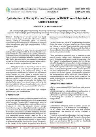
ThetwoconfigurationsofFluidViscousDampers(FVD)with datathatcanbeusedformodellinginETABS2019.
LiveLoadonFloor 2.5kN/m²
Journal of
and
Numberofstories G+8
ThestudiesareconcernedtoIOdifferentconfigurationsof G+9storeybuildingunderseismiczoneIIandV.
2.2 LOAD COMBINATIONS:
(IRJET) e
I Inverteddoubledamper,FC Column,C Corners
Volume: 09 Issue: 03 | Mar 2022 www.irjet.net ISSN: 2395 0072 ISO 9001:2008
Densityofconcrete 25KN/m^3
FVD 44 300 0.3 25000
Fig 1:Fluidviscousdampers
2.1 DESIGN DATA:
M Middlecolumn,T Evencolumn,S Singledamper,
Typeofstructure Special moment resisting RC Frame
Beamsize 300*450mm
Gradeofconcrete M25(fck=25N/mm^2)
Thecomparisonhasbeenmadebetweenthestructure without damper and structures with dampers. A G+9 storeystructurewith10differentconfigurationsbased ontheplacementofdampersareconsidered
Table 2: Details of FLUID Viscous damper
International Research Engineering Technology ISSN: 2395 0056
Eachfloorheight 3
LiveLoadonroof 2.5kN/m²
The models considered in this dissertation work are tabulatedintablebelow
© 2022, IRJET | Impact Factor value: 7.529 |
DL+LL+FF
Columnsize 600X600mm
1. Fluid viscous dampers & lock up device’s clevis clevis
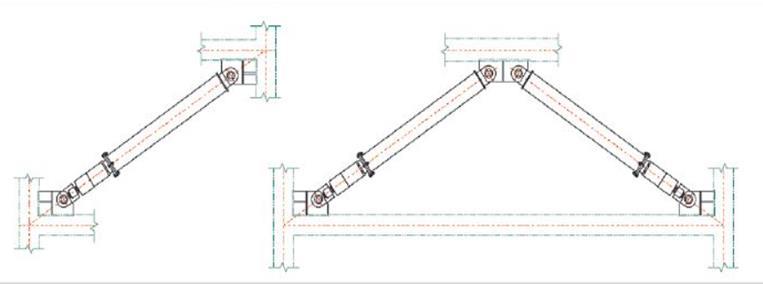
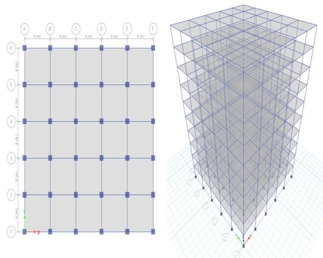
Model G+9 with each storey height 3m is considered. The model has 5 bays in both the horizontal plane each of 4m width.Thus,thetotalplanareawillbe400sq.meters.
Fig 2:RCBareFrameModel
DESCRIPTIONOFTHEMODELS:
Heightofbuilding 30m,G+9
Slabthickness 150mm
Zone 2,5
2.configuration.Fluidviscousdampers&lock updevice’scheverontype configuration
BF
Chart 2:BaseShear

2.3.1 FUNDAMENTAL TIME PERIOD

1 RCbareframe
BMTHI
2.3.2 BASE SHEAR
9 RCbareframe,dampersinmiddle column,doubletophalfstoreys
BBHMI
Chart 1:Fundamentaltimeperiod.
Timeperiodofthebareframestructureisfound;reduced whendampersareaddedtothestructure.
BTBHI
BMFCI
5 RCbareframe,dampersinmiddle column, double bottom half storeys
The important parameters under consideration are listedbelow. time
elodm
Modalanalysischaracterizestheseismicpropertiesof anelasticstructurebyidentifyingitsmodeofvibration. Theresponseofthestructureisdifferentateachofthe differentnaturalfrequencies.
2 RCbareframe,dampersinmiddle column,singleallstoreys
7 Rs bare frame, dampers at even column, double bottom half storeys
4 RCbareframe,dampersinmiddle column,singlebottomhalfstoreys
8 RCbareframe,dampersinmiddle column,singletophalfstoreys
3 RCbareframe,dampersinmiddle column,doubleallstoreys
International Research Journal of Engineering and Technology (IRJET) e ISSN: 2395 0056 Volume: 09 Issue: 03 | Mar 2022 www.irjet.net p ISSN: 2395 0072 © 2022, IRJET | Impact Factor value: 7.529 | ISO 9001:2008 Certified Journal | Page1659 2.3 RESULTS AND DISCUSSIONS
Thetimeperiod obtained fromthemodalanalysisdoesnot match with time period from codal formulae therefore provisionshavetomadeinthecodeforthebetterresults.
BTAS
Fundamental
Details EULATURNOMENC
BMFCS
BBHMS
10 RC bare frame, dampers at corners,singleinallstoreys BACS
BMTHS
6 RC bare frame, dampers at even column,singleallstoreys
Thebuildingwithmoreseismicweightwillbehavinghigh baseshearandlowtimeperiod.
period Basereaction Displacements Acceleration Storeydrift
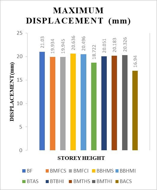
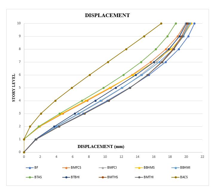
Chart 3:DisplacementcurveofG+9storeybuilding Belowfigureshowsthemaximumdisplacementgraphofall themodelsunderzoneV
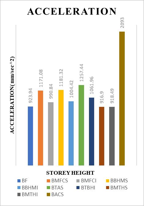
2.3.4 ACCELERATION:
Displacementofstructureisreferredtolateraldisplacement atthetopofframe.Duetoinertiacausedbylateralforcethe displacement is referred as lateral displacement. Displacementwillbeminimumatthebaseandmaximumat the top of frame. Displacement of the structure increases withincreaseinheightofthestructure.
International Research Journal of Engineering and Technology (IRJET) e ISSN: 2395 0056 Volume: 09 Issue: 03 | Mar 2022 www.irjet.net p ISSN: 2395 0072 © 2022, IRJET | Impact Factor value: 7.529 | ISO 9001:2008 Certified Journal | Page1660
Chart -4:MaximumDisplacement
In order to study the dynamic behaviour of the structure, acceleration is one of the important factors underconsideration.
Damperswheninstalledatthebottomhalfofthestructure, shearforceisfoundtobeeffectivelysharedbythedampers withinthestructure.
2.3.3 MAXIMUM DISPLACEMENT
DuetotheMaxwellmodellingofdampers,thestiffness of the structure is increased. Thus, frequency of the structure increases. As the frequency increases the fundamental time period decreases leading to an increaseintheacceleration.
Itisobservedeveninthemodelsunderconsideration thattheaccelerationofthestructureswithdampersis higherthanthestructureswithoutdampers.
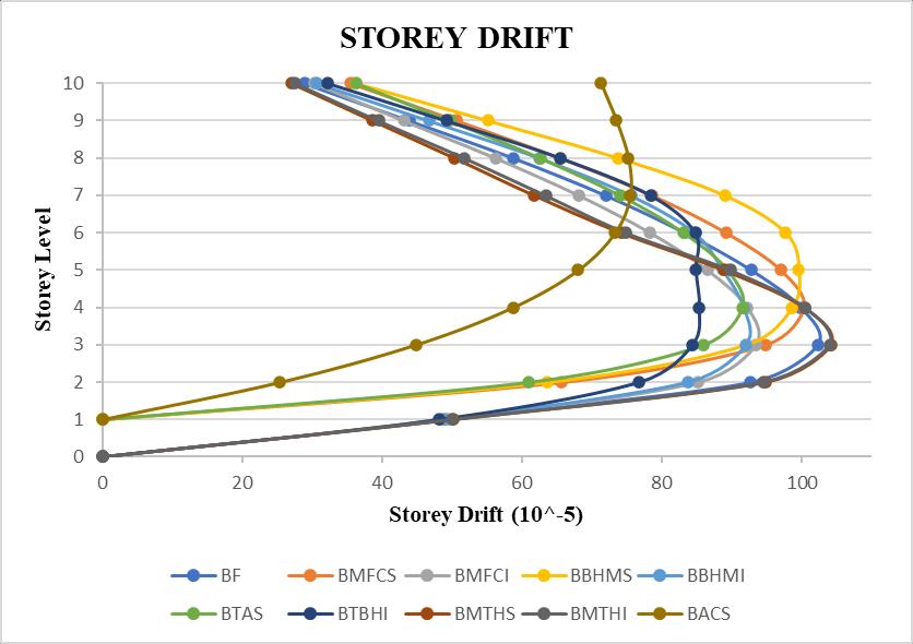
ThestoreydriftisappreciablyreducedinBACS(bareframe dampersattheentirestoreyheightsingle)configuration.
model is stiffer when compared to other configurationshencetheyshowhigheraccelerationvalueby 126.53%whencomparedtobareframemodel.
3.Thebaseshearofthebareframestructureisfoundtobe reducedwhenthestructureisstiffenedatthebaseandorat thebottomhalfofthestructure.
According to IS 1893(Part 1):2016 clause7.11.1, the storeydriftisthedisplacementofonelevelrelativeto the other level above or below. Chart 6 shows storey driftgraphofG+9storeybuilding.Andallthevaluesare tabulated. 6 DriftscurvesofG+9storeybuilding
8.BTBHI.Itisconcluded
Chart
:
5.Incomparison betweenBTASandBACS,thebaseshear valueofBACS (dampersat All corner)is quitelesser than BTAS (dampers at the even column, entire storey height) thoughithassamenumberofdampers.
6.Intermsofplacingandpositioning,Baseshearforsingle dampersinmiddlecolumnBMFCSisgraterwhencompared todampersplacedatevencolumnBTAS.
Theseismicbehaviourofthereinforcedconcretestructureis judgedbyanalysingparameterssuchasdisplacement,storey drift,acceleration,baseshearandfundamentaltimeperiod. All the results are well within permissible limits. The following conclusions can be made based on the analysis carriedout.
of bare frame structure there is about 19.4% reductionsinthedisplacementresponsewhendampersare installed at all the floors in the corner for G+9 storey
International Research Journal of Engineering and Technology (IRJET) e ISSN: 2395 0056 Volume: 09 Issue: 03 | Mar 2022 www.irjet.net p ISSN: 2395 0072 © 2022, IRJET | Impact Factor value: 7.529 | ISO 9001:2008 Certified Journal | Page1661 Chart 5:MaximumAcceleration
1. Time period of the bare frame structure is found to be reducedwhendampersareaddedtothestructure.Sincethe timeperioddeterminedbymodalanalysisdiffersfromthe time period determined by codal formulae, modifications mustbeincludedinthecodeforbetterresults.
2.3.5 STOREY DRIFTS:
4.Baseshearoftwomodels(BMTHIandBTHS)wherethe dampers are placed at the top half of the structure is not effectiveinthereductionofvaluesincemassissignificantat thetop.
2.Structureswherethedampersareatthecornerstoreyfull (BACS)haveshownsignificantreductioninthevalueoftime period. This Model (BACS) has shown about 45.25% reductioninthevalueoftimeperiod.
10.building.BACS
3. CONCLUSIONS
7.BaseshearfordoubledampersinmiddlecolumnBBHMIis greater when compare to dampers placed at even column
thatbaseshearatcornersbottomhalfis leastbutasformiddlecolumnitislessthanplacedateven column for single dampers and vice versa for double 9.dampers.Incase
[6] GLORIATERENZI'DynamicsofSDOFsystemswithnon linear viscous damping'. ASCE journal of engineering mechanics.
International ISSN: 2395 0056 09 Issue: 03 | Mar 2022 www.irjet.net ISSN: 2395 0072
Volume:
[3] E Tabs (2015), Integrated software for structural analysis and design. Version 15.0.0. Berkeley (California).Computers&Structures,Inc.;2007.
© 2022, IRJET | Impact Factor value: 7.529 | ISO 9001:2008 Certified Journal | Page1662
[2] D.I.NARKHEDE&R.SINHA.'ShockVibrationControlof Structures using Fluid Viscous Dampers'. Indian InstituteofTechnologyBombay,Mumbai 400076,India. 2012M.Young,TheTechnicalWriter’sHandbook.Mill Valley,CA:UniversityScience,1989.
[7] GLUCKN,REINHORNAM,GLUCKJ,LEVYR.‘Designof supplementaldampersforcontrolofstructures’.JStruct Eng1996.
[4] FUY,KASAIK.‘Comparativestudyofframesusingvisco elasticandviscousdampers.JStructEng1998.
Research Journal of Engineering and Technology (IRJET) e
[8] JIANXING CHEN, LIANJIN BAO. ‘Energy dissipation designwithviscousdampersinhigh risebuildings’East China Architectural Design & Research Institute, Shanghai,China2012
[5] GARYCHART. KEVIN WONG.Structural dynamics for structuralengineers.
REFERENCES
p
[1] Study on the effect of viscous damper for RCC frame structurePuneethSajjan1,PraveenBiradar2,Febraury 2018.