Abstract The Indian railway is one of the largest railway networks in the world. Despite being such a large network, the safety parameters of Indian railways are substandard. The safety standards and outdated technology causes numerous train accidents and puts human lives in danger. These lives can be saved by avoiding and eliminating the main cause of such accidents i.e. detecting cracks in railway tracks and detecting obstacles over the track. The objective ofthispaperistodesignanddevelopasystemusingsensors andautomationtodetectandwarnthestationmasterabout possible danger. This paper briefs the sensors like GPS module, GSM modem, IR sensor, PIR sensor used for application of communication purpose, crack detection, and finding of human beings present in the railway track. Here, the GPS module and GSM modem help us to find and send railway geometric parameters of crack detection to the nearest railway station. This paper completes the study of a reliable crack detection system which can also be used in physicalconditions.
International Research Journal of Engineering and Technology (IRJET) e ISSN: 2395 0056 Volume: 09 Issue: 03 | Mar 2022 www.irjet.net p-ISSN: 2395-0072 © 2022, IRJET | Impact Factor value: 7.529 | ISO 9001:2008 Certified Journal | Page1508

Mayank Mishra#1, Rushikesh Bhawar#2, Rehan Yahoo#3, Yogesh Maske*4 #Student, Department of Mechanical Engineering, MIT Academy of engineering, Alandi, Pune, India *Assistant Professor, Department of Mechanical Engineering, MIT Academy of engineering, Alandi, Pune, India ***
Keywords GPS module, GSM module, IR sensor,Railway trackcrackdetection,Ultrasonicdistancemeter
In India, railway transport is the most widely used and common mode of transportation for people, covering over 1, 15,000 km in distance, all over the country[1]. Transportation helps in moving people and goods from one placetoanother[2].Nowadaysweoftenobserveinthenews that railway accidents are quite common. The main reason behind this is due to the presence of cracks and other problems on the railway track. These cracks and other problems with the railway generally go unnoticed due to improper maintenance and manual track line monitoring that is being carried out. For preventing this accident and reducingmanpowerweshoulduseanautomatedsystem.It will help to monitor the presence of cracks and other problems on the railway track and when the crack or any defect found on the track at that instant the crack detecting device will automatically stop moving on the track and find thecracksinsidetherailwaytrack.
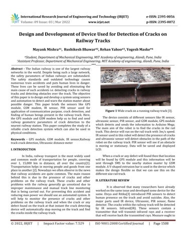
Figure 1 Widecrackonarunningrailwaytrack[3].
Design and Development of Device Used for Detection of Cracks on Railway Tracks

The device consists of different sensors like IR sensor, ultrasonicsensor, PIR sensor,andGSM module,GPS module which detects and sends the information to Arduino Mega. The main aim of the robot is to find the cracks in the rail track.Thisdevicewillrunontherailtrackwith3m/sspeed. IRsensorusedinthisrobotwilldetectthepresenceofcracks andultrasonicsensorwilldetectobstaclesinthepathofthe robotontherailwaytrack.PIR sensorwill seeifanobstacle is moving or stationary. Data will be saved and displayed LCD.
II. LITERATURE REVIEW
I. INTRODUCTION
Whenacrackoranydefectwillfoundthenthatlocation will be found by GPS module and this information will be sent through SMS to the nearby station master by GSM module.AV shapedextrusionbarisusedinthedevicewhich makes the design flexible so that we can use this on the differentsizerailtrack.
It is observed that many researchers have already workedonthesameissueanddevelopedsomedeviceforthe same. Divya and Ritika[3] introduced PIR sensors to detect human presence on the track and avoid suicides. Also, the major parts used IR device, Ultrasonic, PIR sensor, flame detector.Thecrackswithintherailwaytrackwillbedetected by IR sensors. Infrared(IR). These sensors contain a transmitter that will transmit infrared rays and a receiver thatwillreceivebackthetransmittedrays.Measureoughtto
Sr. No. Name Specific Model
Detectcrackontrack
4 GSMModule SIM900
III. MATERIALS AND METHODS
Sendmessagetonearbystationmaster
Useasamicrocontroller
Detectifthereisanyfire
Checkifobstacleismovingorstatic
6 LCDDisplay Generic0829U8OUTCYJCE16x2 Displaythelocationofcrack
10 DCgearedmotor IG32
The integration of all the sub systems is done through a centralPCB Allthesensors,modules,motordrivers,etc are controlled through a Central PCB the robot (Figure2). A dedicated drive PCB for each module containing the necessary electronics is connected to the central PCB usingRS232 and DB9 connectors. Othersignalconnections usestandardlockingPTRconnectors.
B. Circuit Diagram
be taken to form positive that each the transmitter and receiver lies in a very line. If the signal sent by the transmitterisreceivedbythereceiversectionitindicatesthe presenceofcrackwithinthetrack. Afiresensorisaddedfor thesafetyandsmoothrunningofdeviceaswell.
1 IRSensor SHARPGP2Y0A710K0F
DrivetheMotor
A. Materials Required
11 MotorDriver RobodoL298MotorDriver
12 Battery Orange2200Mah24v
Detectthelocationofcrack
battery power provides the microcontroller then it's beginning themotorwithin the forward directionandserial transmission is employed to send the messages to the microcontroller. LDR is employed presence or absence of a crackintherailwayline.
9 FireSensor InfraredFlameSensor
Kuthe,AmaleandBarbuddhye[4]usedtheLCDscreento displaythedata ofthedetectedcrack andsaveitforfurther more time. Paul, Varghese, Menon and Krishn[5] has approach for GPS and GSM in the decice. They discusses a Railwaytrackcrackdetectionusingimageprocessandcould be a dynamic approach which mixes the utilization of GPS followingsystemandLANmoduletosendalertmessagesand thereforethegeographicalcoordinateoflocation.IRdetector is employed to finding the cracks and injury of tracks. unhearable sensors square measure used to discover any obstacle on the rail track. Terribly correct detection and conjointly obtaining correct output compare to the prevailing system. In traditional condition, the motor, LDR, Serial transmission is within the initial stage. Once the
Detectobstacleinfrontofequipment
7 AluminumExtrusionBar V Slot
PrintCouplings,Motormount,etc
3 PIRSensor HC SR501
The Railway Track Crack Detection System has different sensorsdedicatedforuniquetasks.Also,materialslikeV Slot aluminum extrusion bars are used to develop the modular chassis of the robot. Other required parts such as couplings for drive, motor mounts and mounts for sensors are developed by 3 D printing using the PLA material. All other components such as battery, display, microcontroller, modulesandsensorsarementionedintheTable1.
5 GPSModule GY NEO6MV2
Table 1 Sensors, Actuators and Components used in developing the crack detection device.
8 ArdiunoMega ArduinoMega2560R3
SupplyPower
13 PrintingMaterial CREOPLA
International Research Journal of Engineering and Technology (IRJET) e ISSN: 2395 0056 Volume: 09 Issue: 03 | Mar 2022 www.irjet.net p-ISSN: 2395-0072 © 2022, IRJET | Impact Factor value: 7.529 | ISO 9001:2008 Certified Journal | Page1509
Materialforchassis
Drivetheequipment
2 UltrasonicSensor JSN SR04T
Purpose
C. Proposed Solution
E. Mathematical Modelling
device
��=�� Thereforew
ofrobot=12kg
There are two different methods for transmitting and receivingtheultrasonicwaves
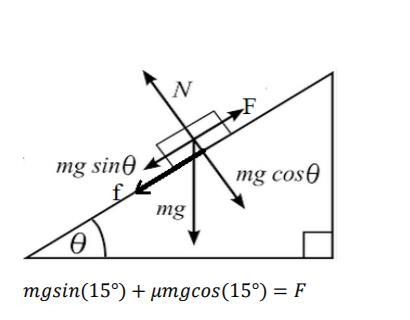
In order to ensure smooth running of robot, an appropriate motor was required that would satisfy the demands of RPM and torque. At first through the help of research papers, speed of the robot was finalized. Then the following calculations were done in order to calculate the torque. Through the values of RPM and torque, motor was finalized.Weight
Radiusofwheel=95mm
D. Railway crack detection by ultrasonic wave

RPMrequired=300
Inthepulse echomethod,thetransmitterandreceiverarein the same module, while in the phase measurement method separate module for transmitter and receiver with different phaseanglesisused.
2.Phasemeasurementmethod.
It is possible to use ultrasonic waves to find flow as well as cracks on the railway tracks. Flow is the internal defect in therailwaytrack,whereasthecrackisthedefectthatcanbe seenontheoutersurfaceofthetrack.Tofindtheflowonthe railway track, we need high frequency ultrasonic waves. On another hand, for finding the crack on the railway track we didn’t require high energy ultrasonic wave and the reason for that is a crack is present o the outer surface of the track
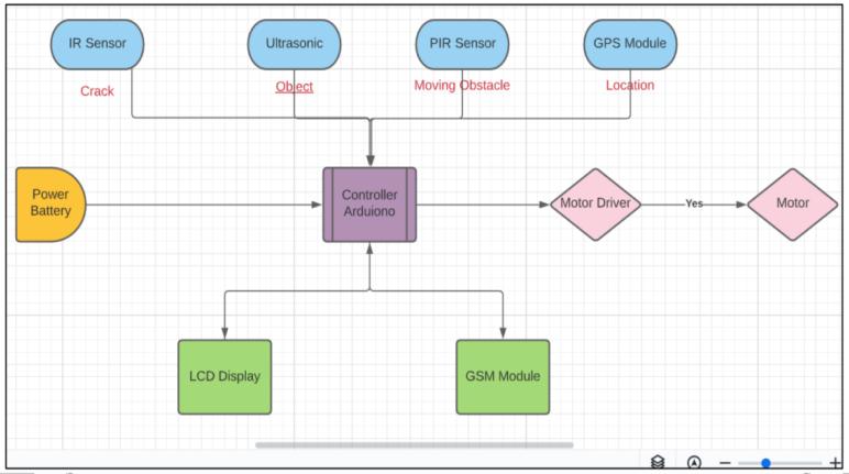
The block diagram shows the schematic diagram of system. Here the sensors i.e. IR sensor, Ultrasonic Sensor, PIR Sensor, GPS Module feed the input data to the microcontroller. The power is supplied to the microcontroller which operates the actuation of motors and sendssignalsanddataaccordingly(Figure3).
International Research Journal of Engineering and Technology (IRJET) e ISSN: 2395 0056 Volume: 09 Issue: 03 | Mar 2022 www.irjet.net p-ISSN: 2395-0072 © 2022, IRJET | Impact Factor value: 7.529 | ISO 9001:2008 Certified Journal | Page1510
Figure 3 Schematic diagram of system.
Figure 4 Ultrasonic wave propagation.
Figure 2 Themaincircuitboardofthe

that is why it is not necessary to present ultrasonic wave in the track, so low frequency ultrasonic wave range of kHz is usedforfindingthecrackonthesurfaceinanymaterialwith ultrasonicwaveswehavetotransmitultrasonicwaveinthe material and receive back these waves and measures the timebetweenthetransmittingofthewaves.
1.Pulseechomethod
Velocityrequired=3m/s
Consideringbodyonanincline,
G. Robot Design
Research Journal of Engineering and Technology (IRJET) e ISSN: 2395 0056 Volume: 09 Issue: 03 | Mar 2022 www.irjet.net p-ISSN: 2395-0072 © 2022, IRJET | Impact Factor value: 7.529 | ISO 9001:2008 Certified Journal | Page1511
TorqueTherefore,onasinglemotor=0.927Nm=9.45kg
W
Our proposed solution has two parallel operations running first one is the detection of crack and the second is thedetectionofanobstacle.Inthedetectionofcrack,weare using a Sharp IR sensor. As the speed of our robot won’t exceed3m/ssharpIRcandetectcrackeasily.Thedata ofIR every20meterwillbeneglectedasitisthegapbetweenthe tracks(aspieceofrailwaytrackis20meterlong). Afterthe detectionofanycrackinassigned20meterdistancebyIRin assigned 20 meter distance, it will send a signal to the microcontroller. The microcontroller will then send the signal to the GPS module to get the exact location [6]. The GPS module will send the data about the location to the microcontroller which further will send the location data to thestationmasteranddriverusingtheGSMmodule[7].For thecaseoflowsignalornosignalwhichisthemostcommon
N
Takingcoefficientoffrictionas F=45.25
Figure 6 shows design of the device. It has modular aluminum chassis which is grey in color and t does have T nutslotsinit.Ithas3 Dprintedmotormountwhichareblue in color. The yellow color L shaped brackets are aluminum T nut slots brackets. Ultrasonic sensors are mounted on front and has navy blue color. Front center is occupied by PIR sensor and has white color. Two IR proximity sensors arealsomountedonchassisandinthecentrallineofwheels and has grey color. The mounts for ultrasonic sensor, PIR sensorandIRproximitysensorhavethesamecolorasofthe sensors. One polycarbonate sheet is mounted in center of chassisandhasgreycolorandithaselectronicsmountedon it. Everything is arranged properly so that the center of gravityshouldbeaslowasitcanbetoreducetopplingeffect

0.35
RPMFactorofsafety=15degree
F. Methodology
Figure 6 RobotDesign
Figure 5 Free Body Diagram of the Robot and forces acting on it.
W��=����
cm
Power=ForcexVelocity
International
Powerforsinglemotor=135.75/4 33.9
problemwhentherobotgoesinsideatunnel,wehaveadded an LCD display screen that will be displaying the location of thecrack andwill saveit.Whentherobotwill getoutof the tunnel the data stored from the LCD screen will be sent to thestationmaster.Inthedetectionofobstacles,weareusing an ultrasonic sensor and a PIR sensor. An ultrasonic sensor will detect if there is any obstacle in the front of the robot and will continuously send signals to the PIR sensor. If ultrasonic finds any obstacle then the robot will stop and then PIR will check if the obstacle is a static or moving obstacle.Incase,iftheobstacleismoving,therobotwillwait until the obstacle passes by and the movement of the obstacle will be checked by an ultrasonic sensor. If it’s a moving obstaclethenit will waittill theobstaclepasses,the passing of the obstacle will be checked by an ultrasonic sensor.Ifit’sastaticobstaclethenitwillsendalocationwith anobstaclemessagetothestationmaster[9].
TotalPower=135.75
=
elevation
The method we proposed in this paper can be used to find the crack in the railway track. By using this technique
[3] S Agrawal, P Bharane,D khan,S Fundkar,S More,A Khande,S Ghait and S Vairale.An Arduino based method for detecting cracks and obstacles in Railwaytracks.IJSRSET.2018; 4
[7] V Divya and R Sreekumar.Crack Detection for Railway tracks and Accident Prevention. International Journal for Research in Applied Science & Engineering Technology. 2017; 5.http://doi.org/10.22214ijraset.2017.2063.
[6] DN Kumar, M Uday,G Brahmini,AMReddy andSM Kumar. Railway Track Crack Detecting System. IJSDR.2017;2
ACKNOWLEDGMENT
for railway track inspection, manpower can get reduced. IR sensor based railway crack detection and PIR sensor based presence of human detection system with GSM module for thealarmingstationwasdeveloped.Highefficientadsimple system is designed ad analyzed successfully. A V shaped extrusion bar has used this device which makes it flexible andcanuseondifferentsizesofrailwaytracks.Inthefuture, this device can be used by Indian railways to inspect and secure widenetwork tracks.Developtechnologythatcanbe used at the domestic ad at commercial places with future vision.
[4] SDKuthe,SAAmaleandVGBarbuddhye.SmartRoot for Railway Track Crack Detection System using LED Photodiode Assembly. Advance Research in ElectricalandElectronicEngineering.2015;2,8 11.
Figure 8 Resultgraphofvelocityversustimecalculation.
anditismaintainedatcentersothateverywheelgetsalmost equal load. The wheels are slotted so that they get fixed on the dark grey color railway track. Further some simulations aredoneonthisdesignandresultsareobtainedfortorquein themotorversustimeandvelocityversustimegraphs.
Our basic motion was smooth in running. The results of motion analysis were also as expected. Our first analysis of MotortorqueversusTimeshowsthatwhenarobotwillstart moving the torque will be highest but as its speed starts increasingthetorquestartsreducing.Oursecondanalysisof Velocityversus Timeshowsthatitsmaximumspeedgoesto 3m/s and minimum is 0. The graph also shows speed as 3m/s because the analysis is done for reciprocating motion whencomingbackitsspeedis 3m/s.

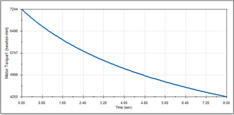
Figure 7 Resultgraphofmotortorqueversustimeanalysis.
[5] R Paul, N Varghese,U Menon and S Krishna K. RailwayTrackCrackDetection.InternationalJournal ofadvanceResearchandDevelopment.2018; 3
International Research Journal of Engineering and Technology (IRJET) e ISSN: 2395 0056 Volume: 09 Issue: 03 | Mar 2022 www.irjet.net p-ISSN: 2395-0072 © 2022, IRJET | Impact Factor value: 7.529 | ISO 9001:2008 Certified Journal | Page1512
V. CONCLUSION
REFERENCES
[1] D Poorathumkal,A Sunny,SPUdayan and YK Jain. Automatic Railway Track Crack Detecting Vehicle. IRJET.2020; 7
TheauthorswishtothankMITAcademyofEngineering forprovidingsupporttocompletethisresearchpaper.
IV. RESULTS AND DISCUSSION
Withthehelpof24voltbatteriesthedevicecanrunabout3 hours consistently which can be increased by adding batteries in parallel. Considering its normal speed in one go thedevicecancoveradistanceof32kilometers.
[2] PNavaraja.CrackdetectionsystemforRailwaytrack by using Ultrasonic and PIR sensor.IJAICT.2014;3.Doi:01.0401/ijaict.2014.01.24.
Volume: 09 Issue: 03 | Mar 2022 www.irjet.net p-ISSN: 2395-0072 2022, IRJET | Impact Factor value: 7.529 | ISO 9001:2008 Certified Journal | Page1513
International Research Journal of Engineering and Technology (IRJET) e ISSN: 2395 0056
[8] A N, D Mohan, F P and S Gopinath. Railway Cracks Detection System. International Research Journal of Engineering&Technology.2016;3.
[9] JM. Armingol , J Alfonso , N Aliane, M Clavijo , CC Sergio,ADLEscalera,JDSer,JFernández,FGarcía, F Jiménez , AM López , M Mata , D Martín, JM Menéndez , SC Javier , D Vázquez and G Villalonga. Environmental Perception for Intelligent Vehicles. Intelligent Vehicles Enabling Technologies and FutureDevelopments,Spain,2018,p.23 11.
©