Mr. Apate
1 1Assistant Professor, Dept. of Mechanical Engineering, AISSMS IOIT, Pune, Maharashtra, India ***
5) Platebox:Itismanufacturedfromthe4mmthickmild steelplatestoformarigidbodyofthewormgearedjack insteadofcastingbody.Itisinstalledwiththewormand
1) Lead toggle: Itisthecomponentatthetopofwhicha loadraisingplateisinstalledonwhichtheconcentrated loadtoberaised,isresting.Itmanufacturefromplain carbonsteelmaterialfollowedbyheattreatmentofcase hardening.
Key Words: Toggle Jack, Battery, Switches, Cables, lead screwetc
Itconsistsofthefollowingdifferentcomponents:
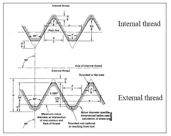
Mechanical machinetogglejacksareavailableinstandard rangesandthecapacitiesvaryfrom5kNto1000kN.Standard classic and symmetric toggle jack configurations include uprightorinvertedtranslatingtoggleunitswithtopplate, clevisorthreadedendonliftingtogglejackanduprightor inverted rotating toggle with flanged lifting nut. Machine toggle jacks are useful for positive mechanical actuation, precisepositioninganduniformliftingspeedsandcanbeuse topush,pullorapplypressureoraslinearactuators.
International Research Journal of Engineering and Technology (IRJET) e ISSN: 2395 0056 Volume: 09 Issue: 03 | Mar 2022 www.irjet.net p ISSN: 2395 0072 © 2022, IRJET | Impact Factor value: 7.529 | ISO 9001:2008 Certified Journal | Page1445

1. INTRODUCTION
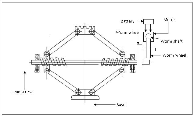
2. CONSTRUCTION OF THE JACK
2.1 Worm Gear operated toggle jack:
2) Nut:Itisthecomponentwhichisrotatedbytheworm shaftbecausethenutisinstalledonthewormgear.The load raising lead toggle advances through this nut UP andDOWN.Itisappliedwiththelubricatinggreaseto haveitssmoothfunctioning.
3) Wormshaft:Itisthatcomponentwhichactuallyrotates thewormgearalongwiththenuttoadvancethetoggle. Itisrotatedmanuallyusingthetommylever.Itperfectly mesheswiththewormgear.
Intheoldendaystheenergyoreffortwasthemanualeffort. But,overtheyearsnewtechnologieshavebeendeveloped and implemented in each and every field. These techniques/devices help in great extent to reduce the manual effort.Mechanical machinetogglejack isonesuch devicecommonlyemployedtoreducethemanualeffort.
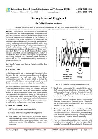
Fig.no.1:Standardscrewthreadnomenclature
Abstract Today’sworldrequiresspeedoneachandevery front.Nowadays,forachievingrapidness,variousmachines andtheequipment’saremanufacturedbythehumanbeing. Engineers are constantly conformed to the challenges of bringing ideas and design into reality. New machines and techniquesarebeingdevelopedcontinuouslytomanufacture variousproductsateconomicalratesandhighquality.Asa partofreducingthemanualeffort,itisproposedtomodify thejackavailableinthemarketwhichisoperatedmanually intoelectricoperatedjack.Infast movingworld,timeisvery important that’s why we decide to manufacture electric operatedjackwhichcanremovethepuncturedcartyrein shortesttime.Also,theotherneedofjackiseasytohandle and having compact size. Less man power required to operatethisjack.So,womencanalsoeasilyremovethecar tyrebyusingthisjack.
Battery Operated Toggle Jack
Ashish Shankarrao
4) Worm gear wheel: It the component being rotated by the worm shaft. It is used to transmit the power betweenshaftswiththeperpendicular,nonintersecting axes.Thewormwheelisessentiallyahelicalgearwitha facecurvedtofitaportionofwormperiphery.
International Engineering Technology ISSN: 2395 0056
and
worm gearing along with the lead toggle and nut arrangementholdfirmly.
concept of jack:
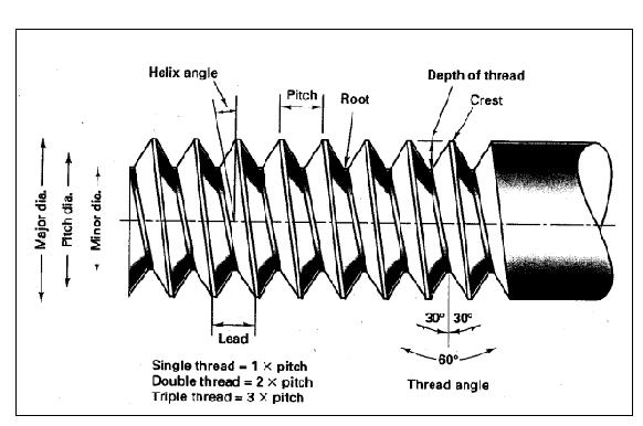
Fig. no. 2: Unified screw thread geometry form
(IRJET) e
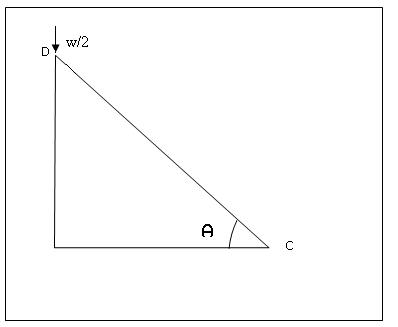
Fig.no. 4: Design concept of jack
Fig. no. 3: Construction of toggle jack with worm &worm wheel
3. DESIGN3.1Design
Research Journal of
©
7) Foot platform: It is the circular plate which holds the concentrated load firmly without slippage. It may be providedwiththeserratedareatoholdtheloadfirmly.
|
Volume: 09 Issue: 03 | Mar 2022 ISSN: 2395 0072 2022, IRJET Factor value: 7.529 ISO 9001:2008 Certified Journal Page1446
www.irjet.net p
| Impact
Theaimofourprojectistoliftthecar(Maruti800) using toggle jack with the help of DC motor which can be operaedby12voltbatteryofthecar.Firstwehavecalculated theweightofthecarandfromthistheloadcomingonthe
|
6) Toprest:Itisatrapezoidalfootrestoverwhichallthe concentrated load of the car and the jack is resting. It formsarobusttoptobecoupledwiththecarbodyor theaxleforthecompletejack.
Resistance
Thetogglescrewismadeupofmalleablesteelforwhichthe ultimate strength is 450 Mpa. As the toggle screw is subjectedtoveryroughhandling,wehavetoconsidermore factorofsafety
Minimum ground clearance for jack : 60 mm from the ground
Maximum Lift :430mmfromthegroundlevel.
Maximum load capacity of jack: 10000N
However,themostimportantfactoraffectingtheselectionof materialforengineeringdesignisthepropertiesofmetalsin relationtotheirintendeduse.Thepropertiesofmetaldefine aspecificcharacteristicofthematerialandbehaviorsofthe metalunderdifferentconditions.Wehaveselectedmalleable carbon steel for fabrications of various component of our project due to following properties and composition of material.
Jack for maruti car
Total weight of the car: 1 ton of concentrated load with concentratedcentreof gravity.
International Research Journal of Engineering and Technology (IRJET) e ISSN: 2395 0056 Volume: 09 Issue: 03 | Mar 2022 www.irjet.net p ISSN: 2395 0072 © 2022, IRJET | Impact Factor value: 7.529 | ISO 9001:2008 Certified Journal | Page1447
Thetotaltensilepullonthesquarethreadedscrew
Figureno.6:Tensilepullonthreadedscrew
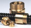
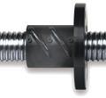
Fig.no.5 : Toggle lead screw
Time required to lift wheel in upward direction: 200 mm/min
Following are some of the important factors on which selectionofmaterialisbased: Availabilityandcostofmaterial andrigidity to weldability
Design of Toggle Screw:
fatigue Impactresistance Hardness Weight Machinabilityand
Weight of jack :15kg
Strength
W=2FF=w/2=10000/2
eachwheelofthecar.Thenwehavemeasuredtheclearance betweenthegroundandaxle.Asweknowtheload&lifting length,wehavecalculatedthepitchoftheleadscrew,then with the help of pitch & lifting length we have calculated speedoftheleadscrew.Fromthespeedoftheleadscrew& speed of the motor we have selected the particular speed ratio for worm gearing mechanism. From above data we havedesignedthetoggleleadscrew,nut,pin,worm,worm wheel. After that we have designed worm wheel shaft for bending&twistingmoment.Byusingthediameterofworm wheelshaft&radialloadcomingonshaftatbearing,wehave selected the bearing. From this we have selected the DC motor.
3.3 Data for Design:
3.2 Material Selection:
15=10000÷[(π/4)(142 122)xn]
Meandiameterofthescrew, d=do (p/2) =14 (2/2)
Shearstressinthescrewduetotorque
Compressivestressisless.(100>89.03).
Letdc=corediameterorscrew.
DuetowhichlinkCDisintension.
100=10000÷[[π/4]×dc2]
Directtensileorcompressivestressduetoaxialloadisgiven by,
Weknowthat, tanα=p/πd =2/π×13=0.048
5000 =10000/(2xtanθ) Ө=45˚
=10000[(0.048+0.15)÷(1 0.048×0.15)]
τ=(16T)÷(πdc3) =(16×13016.9)÷(π×123) =38.36mpa
F=W/(2xtanθ)
Weknowthatdirecttensilestressinthescrew
Formiddlesteel
Volume: 09 Issue: 03 | Mar 2022 www.irjet.net p ISSN: 2395 0072
PbLet,=
ForsafetyweconsiderPb=15N/mm2
Pb=W1 /[(π/4)(d02 dc2)×n]
Bearingpressurebetweenthethread
d Let=13mmus,nowcheckforprinciplestress
Hencedesignissafeforgivenload.
Thebearingpressureinbetween13to17N/mm2
International Research Journal of Engineering and Technology (IRJET) e ISSN: 2395 0056
6c =W÷[[π/4]×dc2]
P=pitchofscrew=2mm (fromstandardtable)
TorquerequiredtorotatethescrewT=P(d/2)=(2002.6×13)÷2 =13016.9N.mm
Frictionangle
6t=w÷(π÷4×(dc2))
3.3.1 Design of nut:
=10000÷(0.7855(122))
F=5000N
P=Wtan(α+ψ)
dc=12mm
6t=89.03mpa
n=No.ofthreadcomeincontactwithnut
n=16
SupposepullFactsontheleftnut,
P=2002.6N
© 2022, IRJET | Impact Factor value: 7.529 | ISO 9001:2008 Certified Journal | Page1448
6c=100mpa (middlesteel)
Nominalorouterdiameterofscrew; do=dc+p =12+2 do=14mm
Nowweknowthateffectrequiredtorotatethescrew
Thedistancemovedbythescrewin1rotationis2mm
=W[(tanα+tanψ)÷(1 tanαtanψ)]
α=2.8˚
Ψ=tan 1 8.53=µtan 1µ Tanψ=0.15
Wetake, d1 =10mm
A Areaoflink(c/s)
A=3×62
I=(1/12)(t1×b13) =2.25×6×4
and
t=thicknessofnut
t=pxn =2x16
Wcr =(6c×A)/[1+a[L/K]2]
Assumingafactorofsafety=5, thelinkmustbedesignedforthebucklingloadof
L=165mm
International Research Journal Engineering Technology (IRJET) e ISSN: 2395 0056
b1 KK==18mmI/ARaidsgurationIMovementofinertia
Wcr=2500x5 =15200N Let, t1=Thicknessofthelink
b=Widthofnut
3.3.3 Design of link:
Loadonthelink=F/2=5000/2 =2500N
Assumet1=6mm
Assumingthatthewidthofthelinkis3timesofthethickness oftheblink, 1=3t1
Wcr = (100×108) / [1+ (1/7500)(L/5.19)2]
3.3.2 Design of pin:
b1=Widthofthelink
A=3×t2
F=2×(π/4)×d12×τ 5000=2×(π/4)×d12 ×38.36 d1 =9.109mm
Lengthoflinkis165mm
Journal | Page
b=1.5xd0 =1.5x14 b=21mm
Accordingtorankinesformulabuckingload(wcr)
Fig no 7: Link
Lengthofscrewportionis Cosa=x/165
Duetotheload,thelinkmaybuckleintwoplanesat rightangletoeachother.Forbucklingintheverticalplane (i.e.,intheplaneofthelink),thelinkareconsideredhinged atbothendsandforbucklingintheplaneperpendicularto theverticalplane,itisconsideredasfixedatthebothends. Weknowthattheloadonthelink t1
Find the nut dimension:
b1 d1
I=2916
t=32mm
©
Let, d1 =diameterofpininthenut
A=108mm2
Wcr =12500N
Volume: 09 Issue: 03 | Mar 2022 www.irjet.net p ISSN: 2395 0072 2022, IRJET Impact Factor value: 7.529 | ISO 9001:2008 Certified 1449
|
of
Weknowthat, x/Ln=(1/2π)×[(1/sinλ)+(V.R/cos λ)] 34/Ln=(1/2π)×[(1/sin250)+(10/cos 250)]
Pressureangle(Ø)=200 P=240watt
No. of (n=startsTw) Single Double Triple Quadruple sextuple
Wehave, L=240mm
Velocity Ratio (V.R.) = 10:1 Center distance(x)=34mm
Axialpitchofthethreadontheworm.(Pa)
Pa=(17.59/3)
Volume: 09 Issue: 03 | Mar 2022 www.irjet.net p ISSN: 2395 0072 2022, IRJET | Impact Factor value: 7.529 | ISO 9001:2008 Certified Journal | Page1450
Ln=15.94mm
LengthofscrewedportionL=2xL=232mm
PressureAngle(Ǿ)in Degrees. 14.5 20 25 30
From5.1&5.2tablewefindthatforavelocityratio of10,thenumberofstartsor threadsontheworm.
From 5.2 table we find that for a velocity ratio of 10, the numberofstartsorthreadsontheworm.
Table no.2: No. of starts used on the worm for different velocity ratio
Pa=5.86mm
Table no.1: Recommended values of lead angle & pressure angle
Pa=Pc=πxm,wheremismodule m=Pa/π=(5.86/3.14)
Let, Ln=Normalleadand λ=Leadangle
Sincetheaxialpitchofthethreadsonthewormisequalto thecircularpitchofteethonthewormgear
Weknowvalueof(λ/Ln)willbeminimumcorresponding to.
Given Data:
n=Tw=3
ratioVelocity 36 above& 12 to 36 8 to 12 6to12 4to10
Forsafety
Sowehaveselectedmotorhavingpower240wattsforjack.
Cot3 λ=V.R.=10 λ=250
3.3.4 Design of Worm and Worm wheel:
Torqueofmotor=1067N mm
Fromspeed&torqueratio,wehavecalculatedthetorqueof motor.(100/1220)=(Torqueofmotor/13016.9)
Weknowthetorqueonleadscrew&speedoftheleadscrew is 13016.9 N mm & 100 rpm respectively. So we have assumed1220rpmfordcmotoravailableinthemarket.
Powerofthemotor=(2×π×N×T)/60 =(2×3.14×1220×1067)/60 P=160watt
©
Design of Worm:
Andaxiallead, (l)=Ln/cos(λ) l=17.59mm
International Research Journal of Engineering and Technology (IRJET) e ISSN: 2395 0056
x=Cos45×165 x=116
Lead Angle (λ) in Degrees. 160 2516 3525 4535
Axialpitchofthethreadsontheworm.(Pa)
b=(2.15xPc)+5 =(2.15x6.28)+5 b=18.520mm
l= (Paxn)=6.28x3
Volume: 09 Issue: 03 | Mar 2022 www.irjet.net p ISSN: 2395 0072
m=1.87
Andfacewidth(b)
DT=63.60mm
=60+(0.572 x 6.28)
Dw=12.86mm
Letustakethestd.Valueofmodule,m=2mm
Dow=16.44mm
3.3.5 Design of Worm Gear:
DG=(mxTG) =(2x30)
Fromtablewefindoutsidedia.ofwormgear(DOG)
Te=[M2+T2]1/2 =[(99929.2)2+(28.65x10³)2] ½
Pa=6.28mm
Axialleadofthethreadsontheworm.(l)
l= 18.84mm
h=(0.623xPc) =0.686x6.28 h=3.91mm
Outsidedia.ofwormDow(Dow)=Dw+(2xa) =12.86+(2x1.79)
Letusnowthecheckthedesignedwormgearfromthestand pointoftangentialload lenttwistingmoment(Te),
Te=3.14/16xtxd3 d=20mm
Since the velocity Ratio is 10 and the worm has double threadsthereforeno.ofteethonthewormgear, (TG)= 10x3
Weknowthatdepthoftooth(h)
DG =60mm
DOG =DG +(0.8903xPc)=60+(0.8903x6.28)
Let, Dw=Pitchcircledia.oftheworm.
© 2022, IRJET | Impact Factor value: 7.529 | ISO 9001:2008 Certified Journal | Page1451
a=1.79mm
Wehaveusedfibrematerialforwormgear. Weknowthatpitchcircledia.ofwormgear(DG)
Ln=15.94mm
Te=103955.12N mm
International Research Journal of Engineering and Technology (IRJET) e ISSN: 2395 0056
ThroatDiameter(DT D)
Fromtablewefindthatthefacelengthofthreadedportionis (LW) LW =Pc(4.5+0.02Tw) ……. (Pa=Pc) =6.28(4.5+0.02x3) Ln=28.63mm
Andnormalleadofthethreadsontheworm.(Ln)
Pa= (πx m)=(π x2)
Ln=(lxcosλ) =(17.59xcos250)
DOG =65.59mm
Weknowthat tanλ=[1/(πxDw)] Dw = [1/(π xtanλ)]
T =DG +(0.572x Pc)
Andaddendum(a) a=(0.286xPc)
TG=30
www.irjet.net p
3.3.6 Selection of Bearing:
Fr=Radialload=2498.2N
Volume: 09 Issue: 03 | Mar 2022 ISSN: 2395 0072 Impact Factor value: 7.529 ISO 9001:2008 1452
We have considered the life (L10h) of the bearing for this applicationwhichisequalto6000hrs.
and
Withthehelpofloadfactor=1.5 wehaveselectedthevalueofradial(X)&thrustfactor(Y) fromtable.
From above torque, we have calculate the power of the motor Poweras,=(2xπxNxT)/60=161watt.
d=20.5mm
Hereconcludingthat,Electricoperatedtogglejackisusedto replace the tyre of the car with no effort when it gets punctured, in shortest time, and it is easy for handling & operating, it is compact & portable. Women, children’s & agedpersonscanoperatethejack.
C
of
) / 106 L10
Forthemoreefficientperformance,weselect12vDCmotor havingpowerof240watt.
e
M=101942.16N mm
D.C. Motor principles:
P
Hence, C=2498.2x361/3
Me=½{M+[M2 +T2]1/2}
By considering the speed ratio between motor and lead Torquescrew,ofthemotoris1067N mm.
International Research Journal Engineering Technology (IRJET) ISSN: 2395 0056
Ccapacity=Px(L10)1/3 L10
Certified Journal | Page
C=8248.87N
.
So,diameterofshaftis20mm.
C=Px(L10)1/3
X=1&Y=0 dynamicload(N)
P=(XxFr)+(YxFa) =(1x2498.2) =Dynamicload =(60xnxL10h =(60x100x6000)
Motor selection consists of following point: Application:Drivingchaindrive Voltage:12V Speed:1000rpm Workingcondition:Continuous Frequency:50Hz
|
(1) Speed suitable for specifications:
Selectamotorthatmeettheabove.
Becausetherequiredspeedis100rpm,thegearratiothat realizesaratedmotorspeed of1000rpmis1000/100=10. Thereforeuseagearratioof1/10
(2) Calculation of required torque:
3. CONCLUSIONS
[1] Prof.NitinchandraR.Patel,SanketkumarDalwadi,Vijay Thakor&ManishBamaniya,“DESIGNOFTOGGLEJACK CONSIDERINGMATERIALSELECTIONOFSCERW NUT P = 2498.2 N
PLet,=Equivalent
Fa=Thrustload(N)
An Electric motor is a machine which converts electrical energy into mechanical energy. Its action is based on the principlethatwhencurrentcarryingconductorisplacedina magnetic field, it experiences a mechanical force whose direction is given by Fleming Left hand Rule and whose magnitudeisgivenbyF=BxIxlNewton.
REFERENCES
© 2022, IRJET |
Me=3.14/32xSbxd3
3.3.7 Motor Selection:
L10 = 36 million rev.
/ 106
Fromdiameteroftheshaft&dynamicloadcapacitywehave selected Bearing No. 6004
[3] MusaNicholas,AbodunrinTosin&OladipoSarafadeen, “Development of an Integrated Toggle Jack for Lifting Automobiles,”ISDAE,Vol.7,No.1,2016,pp 21to30
International Research Journal of Engineering and Technology (IRJET) e ISSN: 2395 0056
© 2022, IRJET | Impact
[2] AbhishekMadhukarBarewar,AbhishekAshokPadole, YugalDhanpalNagpure,PranavShivrajGaupale,Sagar Bhimraoji Nagmote, Chandan Kumar Ram & Rupali Suresh Raut “Fabrication of automatic screw jack,” IJARnD,Vol.3,Issue4,2018,pp 64to67.
[4] Dr.VijayKuma & Mr. K. P.Sing,“AUTOMATICSCREW JACK TO REDUCE MAN EFFOR,” GJFRA, VOLUME 7, ISSUE 2,FEBRUARY 2018•PRINTISSNNo2277 816
[5] Mr. Onkar Vade, Prof. Dr. Mr. Premendra Bansod, “Design and Optimization of a Scissor Car Jack for ImprovementinOperation,”IJSEAT, Issue5,2021,9.3.
[6] ManojRPatilandSDKachave,“Designandanalysisof scissor jack,” International Journal of Mechanical EngineeringandRoboticsResearch,vol.4,pp.327 335, January2015.
Mr. Ashish Shankarrao Apate Assistant Professor, AISSMS IOIT, Pune,Maharashtra,India.

Volume: 09 Issue: 03 | Mar 2022 www.irjet.net p ISSN: 2395 0072 Factor value: 7.529 | ISO 9001:2008
[7] ChetanS.Dhamak,D.S.BajajandV.S.Aher,“Designand optimization of scissor jack,” International Journal of Advances in Production and Mechanical Engineering, vol.2,pp.29 34,2016.
[8] C.S.Dhamak,D.S.Bajaj,V.S.AherandG.Nikam,“Design andstandardizationofscissorjacktoavoidfieldfailure,” International Journal of Advance Research and InnovativeIdeasinEducation,vol.1,pp.1 10,2015.
BIOGRAPHY
Certified Journal | Page1453
COMBINATION,”IJIRSET,Vol.2,Issue5,May2013,pp 1748to1756.